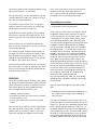
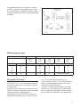
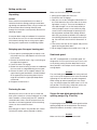
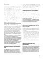
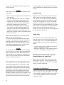
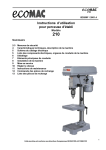
1
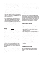
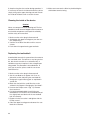
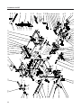
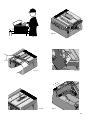
FET
Manual
Replacement Parts List
Part-No.
description
Part-No.
description
37070 - 01
Motor
27070 - 41
Screw
27070 - 02
Motor Casing, small
27070 - 42
Saw table
27070 - 03
Motor Casing, big
27070 - 43
Screw
27070 - 04
Stop plate
27070 - 44
Cover plate
27070 - 05
Screw
27070 - 45
Screw
27070 - 06
Nut
27070 - 46
Front cover
27070 - 07
Nut
27070 - 47
Screw
27070 - 08
Fan
27070 - 48
Washer
27070 - 09
Set screw
27070 - 49
Screw
27070 - 10
Cap
27070 - 50
Indicator
27070 - 11
Screw
27070 - 51
Washer
27070 - 13
Ball bearing
27070 - 52
Hand wheel
27070 - 14
Poully
27070 - 53
Knurled nut
27070 - 15
Toothed belt
27070 - 54
Screw
27070 - 16
Poully
27070 - 55
Riving knife
27070 - 17
Spacer disc
27070 - 56
Pin
27070 - 18
Screw
27070 - 57
Shaft locking clip
27070 - 19
Connecting rod
27070 - 58
Saw blade cover, left half
27070 - 20
Distance bushing
27070 - 59
Saw blade cover, right half
27070 - 21
Angle adjusting plate
27070 - 60
Screw
27070 - 22
Axis
27070 - 61
Screw
27070 - 23
Extension spring
27070 - 62
Plate
27070 - 24
Lower casing
27070 - 63
Screw
27070 - 25
Lustre terminal
27070 - 64
Upper casing part
27070 - 26
Connecting cable
27070 - 65
Holder
27070 - 27
Connecting cable
27070 - 66
Screw
27070 - 28
Holder
27070 - 67
Knurled nut
27070 - 29
Switch
27070 - 68
Washer
27070 - 30
Screw
27070 - 69
Holder for upper casing part
27070 - 31
Screw
27070 - 70
Hinge
27070 - 32
On-Off switch
27070 - 71
Screw
27070 - 33
Cover
27070 - 72
Nut
27070 - 34
Screw
27070 - 73
Screw
27070 - 35
Allen key set
27070 - 74
Screw
27070 - 37
Saw blade
27070 - 75
Blocking lever
27070 - 38
Washer
27070 - 76
Bushing
27070 - 39
Screw
27070 - 77
Screw
27070 - 40
Cover plate
27070 - 78
Extenable saw bearing
2
Replacement Parts List
Part-No.
description
Part-No.
description
27070 - 79
Guiding rod
27070 - 117
Screw
27070 - 80
Set screw
27070 - 118
Connecting piece
27070 - 81
Supporting stop
27070 - 119
Screw
27070 - 82
Resting ball
27070 - 120
Rubber hose
27070 - 83
Compression spring
27070 - 121
Label „angle scale“
27070 - 84
Set screw
27070 - 122
label „ fine adjustment“
27070 - 85
Pin
27070 - 123
Label „scale“
27070 - 86
Supporting lever
27070 - 139
Board
27070 - 87
Metal core
27070 - 125
Connecting cable
27070 - 88
Lock washer
27070 - 126
Label „Exhaustion“
37070 - 89
Cable connection
27070 - 127
Label „Transport lock“
27070 - 90
Tension relief
27070 - 128
Label „Proxxon“
27070 - 91
Downer strain relief clamp
27070 - 129
Label
27070 - 92
Upper strain relief clamp
27070 - 130
Grommet
27070 - 93
Cover
37070 - 131
Rating plate
27070 - 94
Screw
27070 - 132
Cable grommet
27070 - 95
Ruler
27070 - 133
Cable grommet
27070 - 96
Fine adjusting screw
27070 - 134
Work piece pusher
27070 - 97
Nut
27070 - 135
Screw
27070 - 98
Clamping piece
27070 - 136
Stop
27070 - 99
Guiding rod
27070 - 137
manual (not shown)
27070 - 100
Guidin piece
27070 - 138
Shaft
27070 - 101
Longitudinal stop
27070 - 102
Screw
27070 - 139
27070 - 140
Board
Plate
27070 - 103
Plate
27070 - 104
Knurled nut
27070 - 105
Clamping piece
27070 - 106
Clamping lever
27070 - 107
Stop bar
27070 - 108
Guidance
27070 - 109
Pointer
27070 - 110
Screw
27070 - 111
Set screw
27070 - 112
Mitre gauge
27070 - 113
Washer
27070 - 114
Knurled screw
27070 - 115
Knurled screw
27070 - 116
Centering device
3
21 22
1
2
3
20
8
9
10
4
11
12
5
13
14
15
6
19
4
5
7
3
16
17
7
18
19
10
4
11
6
12
5
13
14
15
6
16
17
18
7
19
20
8
21
22
18
9
23
24
7
17
16
8
9
10
Fig. 2
7
3
8
9
10
90
4
80
11
12
60
5
13
11
40
14
15
16
7
0
17
90
20
6
20
18
40
60
19
10
4
11
12
5
13
14
15
6
16
17
7
18
19
20
8
15
21
22
9
23
24
12
14
13
Fig. 1
Fig. 3
250
190
Fig. 5
Fig. 4
Fig. 5a
4
Fig. 6
Fig. 7
Fig. 8a
Fig. 9
Fig. 8b
Fig. 9a
Fig. 10a
Fig. 10b
Fig. 10c
5
Fig. 11
Fig. 10d
1
3
90
80
1
60
2
40
0
90
20
20
11
5
12
5
13
14
15
6
16
13
14
15
6
2
16
17
7
17
7
18
19
20
21
8
18
19
20
8
21
22
9
22
9
23
60
40
3
10
4
23
24
24
Fig. 13a
Fig. 12
3
6
55
4
4
7
90
1
80
60
40
1
0
90
20
20
40
10
4
11
12
5
13
14
15
6
16
17
7
18
19
20
8
21
60
2
22
9
23
24
Fig. 13c
Fig. 13b
Fig. 14
Fig. 13d
6
Contents:
In general
WARNING!
For Your Own Safety Read Instruction Manual Before
Operating Saw!
Dear Customer!
ALWAYS WEAR EYE PROTECTION
The use of these instructions
• makes it easier to become acquainted with the
device,
• prevents malfunctions due to improper handling,
and
• increases the service life of your device.
Always keep these instructions close to hand.
Only operate this device with exact knowledge of it
and comply with the instructions.
PROXXON will not be liable for the safe function of
the device for:
• handling that does not comply with the usual intended use,
• other application uses that are not stated in the
instructions,
• disregard of the safety regulations.
You will not have any warranty claims for:
• operating errors,
• lack of maintenance.
For your safety, please comply with the safety regulations at all costs.
Only use original PROXXON spare parts.
All rights reserved for further developments within
the meaning of technical progress. We wish you
much success with the device.
General safety instructions
Read and become familiar with this entire instructions manual. Learn the tool`s applications, limitations and possible hazards.
Projectiles thrown away from the machine could
cause serious permanent eye damage. Always wear
safety goggles, not glasses, complying with ANSI
Z87.1 (or in Canada CSA Z94-3-M88). Everyday eyeglasses have only impact resistant lenses. They are
not safety glasses! Safety goggles are available at
many local retail stores. Glasses or goggles not in
compliance with ANSI or CSA could seriously hurt
you when they break.
Important safety regulations
1. KEEP GUARDS IN PLACE and in working order.
2. REMOVE ADJUSTING KEYS AND WRENCHES.
Form habit of checking to see that keys and adjusting wrenches are removed from tool before
turning it on.
3. KEEP WORK AREA CLEAN. Cluttered areas and
benches invite accidents.
4. DON’T USE IN DANGEROUS ENVIRONMENT.
Don’t use power tools in damp or wet locations,
or expose them to rain. Keep work area well
lighted.
5. KEEP CHILDREN AWAY. All visitors should be
kept safe distance from work area.
6. MAKE WORKSHOP KID PROOF with padlocks,
master switches, or by removing starter keys.
7. DON’T FORCE TOOL. It will do the job better and
safer at the rate for which it was designed.
8. USE RIGHT TOOL. Don’t force tool or attachment to do a job for which it was not designed.
9. USE PROPER EXTENSION CORD. Make sure
your extension cord is in good condition. When
using an extension cord, be sure to use one
heavy enough to carry the current your product
will draw. An undersized cord will cause a drop in
line voltage resulting in loss of power and overheating. Table xx? shows the correct size to use
depending on cord length and nameplate ampere
rating. If in doubt, use the next heavier gage. The
7
10.
11.
12.
13.
14.
15.
16.
17.
18.
19.
8
smaller the gage number, the heavier the cord.
Exception No. 1: The reference to the table and
the table itself may be omitted if a statement indicating the appropriate gage and length is incorporated into the instruction. Exception No. 2: The
information regarding extension cords need not
be provided for a permanently connected tool.
WEAR PROPER APPAREL. Do not wear loose
clothing, gloves, neckties, rings, bracelets, or
other jewelry which may get caught in moving
parts. Non-slip footwear is recommended. Wear
protective hair covering to contain long hair. Exception: The reference to gloves may be omitted
from the instructions for a grinder.
ALWAYS USE SAFETY GLASSES. Also use face
or dust mask if cutting operation is dusty. Everyday eyeglasses only have impact resistant
lenses, they are NOT safety glasses.
SECURE WORK. Use clamps or a vise to hold
work when practical. It’s safer than using your
hand and it frees both hands to operate tool.
DON’T OVERREACH. Keep proper footing and
balance at all times.
MAINTAIN TOOLS WITH CARE. Keep tools sharp
and clean for best and safest performance. Follow instructions for lubricating and changing accessories.
DISCONNECT TOOLS before servicing; when
changing accessories, such as blades, bits, cutters, and the like.
REDUCE THE RISK OF UNINTENTIONAL STARTING. Make sure switch is in off position before
plugging in.
USE RECOMMENDED ACCESSORIES. Consult
the owner’s manual for recommended accessories. The use of improper accessories may
cause risk of injury to persons.
NEVER STAND ON TOOL. Serious injury could
occur if the tool is tipped or if the cutting tool is
unintentionally contacted.
CHECK DAMAGED PARTS. Before further use of
the tool, a guard or other part that is damaged
should be carefully checked to determine that it
will operate properly and perform its intended
function — check for alignment of moving parts,
binding of moving parts, breakage of parts,
mounting, and any other conditions that may affect its operation. A guard or other part that is
damaged should be properly repaired or replaced.
20. DIRECTION OF FEED. Feed work into a blade or
cutter against the direction of rotation of the
blade or cutter only.
21. NEVER LEAVE TOOL RUNNING UNATTENDED.
TURN POWER OFF. Don’t leave tool until it
comes to a complete stop.
Additional safety instructions for table
saws:
ALWAYS USE BLADE GUARD, RIVING KNIFE,
AND ANTI-KICKBACK PAWLS on all „through-sawing“ operations. Through-sawing operations are
those in which the blade cuts completely through the
workpiece as in ripping or crosscutting. Keep the
blade guard down, the anti-kickback pawls down,
and the riving knife in place over the blade.
ALWAYS SECURE WORK firmly against rip fence or
miter fence.
ALWAYS USE A PUSH STICK FOR RIPPING NARROW STOCK. A push stick is a device used to push
a workpiece through the blade instead of using your
hands. Size and shape can vary but the push stick
must always be narrower than the workpiece to prevent the push stick from contacting the saw blade.
When ripping narrow stock, always use a push stick,
so your hand does not come close to the saw blade.
Use a featherboard and push blocks for non-through
cuts.
NEVER perform any operation „freehand“ which
means using only your hands to support or guide the
workpiece. Always use either the rip fence or miter
fence to position and guide the work.
NEVER stand or have any part of your body in line
with the path of the saw blade.
NEVER reach behind, over, or within three inches of
the blade or cutter with either hand for any reason.
MOVE THE RIP FENCE out of the way when crosscutting.
NEVER use rip fence as cutoff gage when crosscutting.
NEVER attempt to free a stalled saw blade without
first turning the saw OFF and disconnecting the saw
from the power source.
PROVIDE ADEQUATE SUPPORT to the rear and
sides of the saw table for wide or long work pieces.
Use a sturdy „outrigger“ support if a table extension
more than 24 inches long is attached to the saw.
AVOID KICKBACKS (work thrown back toward you)
by:
A. Keeping blade sharp.
B. Keeping rip fence parallel to the saw blade.
C. Keeping riving knife, anti-kickback pawls, and
blade guard in place and operating.
D. Not releasing the work before it is pushed all the
way past the saw blade using a push stick.
E. Not ripping work that is twisted or warped or
does not have a straight edge to guide along the
fence.
AVOID AWKWARD OPERATIONS AND HAND POSITIONS where a sudden slip could cause your hand
to move into the cutting tool.
CHECK WITH A QUALIFIED ELECTRICIAN or service personnel if the grounding instructions are not
completely understood or if in doubt as to whether
the tool is properly grounded.
USE ONLY CORRECT ELECTRICAL DEVICES: 3wire extension cords that have 3-prong grounding
plugs and 3-pole receptacles that accept the tool’s
plug.
DO NOT MODIFY the plug provided. If it will not fit
the outlet, have the proper outlet installed by a qualified electrician.
USE ONLY RECOMMENDED ACCESSORIES listed
in this manual or addendums. Blades must be rated
for at least 6,0000 rpm. Use of accessories that are
not listed may cause the risk of personal injury. Instructions for safe use of accessories are included
with the accessory.
DOUBLE CHECK ALL SETUPS. Make sure blade is
tight and not making contact with saw or workpiece
before connecting to power supply.
MAKE SURE THE WORK AREA HAS AMPLE
LIGHTING
to see the work and that no obstructions will interfere
with safe operation BEFORE performing any work
using the table saw.
ALWAYS TURN OFF SAW before disconnecting it,
to avoid accidental starting when reconnecting to
power supply.
SAVE THESE INSTRUCTIONS. Refer to them frequently and use to instruct other users. If you loan
someone this tool, loan them these instructions also.
Further safety instructions
This machine is for indoor use only. Do not expose to
rain or use in damp locations.
Use only accessories recommended for this table
saw. Follow the instructions that accompany accessories. Use of improper accessories may cause hazards.
Do not attempt to modify this tool or create accessories not recommended for use with this tool. Any
such alternation or modification is misuse and could
result in hazardous condition leading to possible serious injury.
To avoid injury from unexpected starting or electrical
shock, do not plug the power cord into a power
source receptacle during unpacking and assembly.
This cord must remain unplugged whenever you are
working on the table saw.
If any part is missing or damaged, do not plug the
table saw in until the missing or damaged part is replaced, and assembly is complete. To avoid electrical
shock, use only identical replacement parts when
servicing grounded tools.
For your safety, never connect the plug to the power
source receptacle until the assembly and adjustment
steps are completed, and you have read and understood the safety and operating instructions.
To avoid injury from accidental start, make sure the
switch is in the OFF position and the plug is not con-
9
nected to the power source receptacle before changing any parts or tools (i. e. saw blade)
For your own safety, use only saw blades sized and
recommended for this table saw. Follow the instructions that accompany the millers.
ment, such as those dust masks that are specially
designed to filter out microscopic particles.
Use a vacuum cleaner for wood dust collection as
described in our manual whenever possible.
Grounding instructions:
To avoid fire or toxic reaction, never use gasoline,
naphtha, acetone, lacquer thinner, or similar highly
volatile solvents to clean the table saw.
Do not allow brake fluids, gasoline, or penetrating
oils to come in contact with the plastic parts. They
contain chemicals that can damage or destroy plastics.
When servicing use only PROXXON replacement
parts. Use of any other parts may create a hazard or
cause product damage.
Any attempt to repair or replace electrical parts on
this lathe may create a hazard unless repair is done
by a qualified service technician. Repair service is
available at your PROXXON service center (You find
the address at the back of this manual)
Never work with a device that has faulty or defective
parts. Your table saw might no longer be safe. Therefore, have any damage immediately repaired by the
Proxxon Customer Service!
WARNING:
Some dust created by power sanding, sawing, grinding, drilling, and other construction activities contains
chemicals known to the State of California to cause
cancer, birth defects or other reproductive harm.
Some examples of these chemicals are:
• lead from lead-based paints,
• crystalline silica from bricks and cement and other
masonry products, and
• arsenic and chromium from chemically-treated
lumber.
Your risk from these exposures varies, depending on
how often you do this type of work. To reduce your
exposure to these chemicals: work in a well ventilated area, and work with approved safety equip-
10
1. All grounded, cord-connected tools:
In the event of a malfunction or breakdown, grounding provides a path of least resistance for electric
current to reduce the risk of electric shock. This tool
is equipped with an electric cord having an equipment-grounding conductor and a grounding plug.
The plug must be plugged into a matching outlet that
is properly installed and grounded in accordance
with all local codes and ordinances. Do not modify
the plug provided — if it will not fit the outlet, have
the proper outlet installed by a qualified electrician.
Improper connection of the equipment-grounding
conductor can result in a risk of electric shock. The
conductor with insulation having an outer surface
that is green with or without yellow stripes is the
equipment-grounding conductor. If repair or replacement of the electric cord or plug is necessary, do not
connect the equipment-grounding conductor to a
live terminal. Check with a qualified electrician or
service personnel if the grounding instructions are
not completely understood, or if in doubt as to
whether the tool is properly grounded.
Use only 3-wire extension cords that have 3prong
grounding plugs and 3pole receptacles that accept
the tool’s plug.
Repair or replace damaged or worn cord immediately.
2. Grounded, cord-connected tools intended for use
on a supply circuit having a nominal rating less
than 150 volts:
This tool is intended for use on a circuit that has an
outlet that looks like the one illustrated in Sketch A in
Figure 72.1. The tool has a grounding plug that looks
like the plug illustrated in Sketch A in Figure 72.1. A
temporary adapter, which looks like the adapter illustrated in Sketches B and C, may be used to connect
this plug to a 2-pole receptacle as shown in Sketch
B if a properly grounded outlet is not available. The
temporary adapter should be used only until a prop-
erly grounded outlet can be installed by a qualified
electrician. The green-colored rigid ear, lug, and the
like, extending from the adapter must be connected
to a permanent ground such as a properly grounded
outlet box.
Minimum gage for cord
Ampere Rating
Volts
120 V
240 V
Total length of cord in feet
25 ft.
50 ft.
50 ft.
100 ft.
100 ft.
200 ft.
150 ft.
300 ft.
More Than
Not More Than
0
6
18
16
16
14
6
10
18
16
14
12
10
12
16
16
14
12
12
16
14
12
Description of machine
The FET table saw is a well thought-out machine for
all occurring sawing tasks in the range of small and
fine applications.
A powerful motor, solid mechanics, high-quality materials and meticulous production make this a reliable
tool for all possible sawing applications.
Depending on the utilised saw blades, all types of
wood, many non-ferrous metals, ceramics and plas-
AWG
Not Recommended
tics as well as many other materials can be
processed with the machine. The corresponding saw
blades can be obtained from Proxxon and will be
mentioned in more detail later on.
The bench is made of stable aluminium die casting
and forms one unit together with the motor suspension: The guarantees the highest strength and naturally also affects the precision of the working results.
11
To guarantee the highest possible flexibility, we offer
different types of limit stops that are included with
the machine. So there is something for every application:
There is a longitudinal stop that runs in a guide along
the front of the bench that can be easily shifted and
arrested by hand, or which can be used with the precisely adjustable graduated scale.
Adjusting capabilities in the tenth of a millimetre
range leave nothing to be desired and make it easy
to saw work pieces to the desired, previously adjusted measure.
In addition there is a sophisticated and precise angle
stop which can be extended with an aluminium profile strip with a moving clamping piece for the exact
reproduction of many parts to be sawed out with
equal angles and each with the same dimensions.
The safety aspect was taken care of as well: The saw
blade is covered by a sturdy saw blade guard which
automatically moves up when contact is made with
the work piece, and which only releases as much of
the saw blade as necessary.
Caution!
For your own safety, it is understood that the saw
may never be operated without this protective guard!
Legend (fig. 1)
1. Saw blade guard
2. Saw table
3. Saw blade
4. Connection for dust suction
5. Longitudinal stop
6. Key parking slot
7. Rubber connecting piece for suction
8. Allen key
9. Allen key
10. Push-rod
11. Angle stop
12. Knurled screw for fine adjusting
13. Motor unit
14. Angle scale for saw blade tilt
15. Saw blade adjustment for depth of cut
16. Clamping piece
17. Limit stop strip
18. Mains cable
19. On - Off switch
20. Scale for longitudinal stop
21. Extendable saw support
22. Auxiliary stop
Technical data
The upper part of the device is hinged so that it can
be opened for cleaning and maintenance purposes.
Thus the interior of the device can be cleaned of
chips and dust with a vacuum cleaner, for example.
To exclude any kind of hazard, a switching contact
disconnects the electrics from the power mains
when the upper housing part is open.
But during all cleaning, maintenance and adjusting
work (and of course during sawing) please remember
that your FET is not a play toy but a tool for woodworking and is thus a potential source of danger!
Among others a push-rod for the secure feed of
more compact work pieces and two Allen keys are
also included in the delivery. These can be stored in
a „key parking slot“ on the right side of the housing.
In the interests of your own safety, please carefully
read through and comply with the attached safety
notes, which are also mentioned in these instructions, and make sure that you have also understood
them!
12
Rotational speed:
6000 rpm
Saw blade diameter max.
3 11/32” (85 mm)
Depth of cut max.:
(in wood, with blade
Ø 3 5/32”, 80 mm)
ca. 1” (25 mm)
Saw blade drill hole:
13/32“ (10 mm)
Motor:
Voltage:
Power consumption:
110-120 Volt, 50/60 Hz
1,6 A STS 10 min
Setting up the saw
Caution!
Make sure the mains plug is disconnected!
Unpacking
Caution!
Please note that transport blocks have been attached to the device during packing to avoid damage during transportation. Make sure you remove all
of them before commissioning! Carefully read
through the instructions and especially observe the
following chapter!
A transport block made of cardboard is inserted on
the inside of the saw. This must be removed before
initial commissioning. How to swing up the upper
housing part is explained in the following chapter.
Swinging open the upper housing part
1. Please open the packaging box to unpack, carefully remove the saw and deposit it on a firm and
level surface.
2. Release the knurled screw 1 (fig. 2) and swing up
the upper housing part 2.
3. Permit the latch 3 to engage.
4. Before first commissioning, remove the cardboard
that was used as safeguard during the transport.
5. Release the latch 3 of the support and push the
upper housing part back down. Caution! Hold on
to the upper part when pushing down! Injuries
might be caused if the upper part drops down
unchecked.
6. Retighten knurled screw 1.
1. Swing up the upper part of the saw
2. Permit the latch to engage
3. Now you can see four hexagonal indentations on
the inside above the four screw holes in the housing bottom, see fig. 3. These are intended to receive M6 hexagon nuts, or the heads of M6 (or
similar) hexagon screws. Insert sufficiently long
screws 2 from inside through the opening in the
housing bottom and bolt them through the drill
holes that you previously drilled in the underlay 3.
1. Use a drilling template for the required hole spacing. You will find a sketch with the dimensions at
fig. 4.
4. Then release the latch of the support and push the
upper housing part back down.
5. Do not forget to tighten the knurled screw 1 (fig. 2)!
Saw blade guard
Your FET is equipped with a saw blade guard. It is
designed in such a way that moves up as far as necessary during sawing and then drops back into its
home position. It also adapts to the various adjusted
cutting depths.
Caution!
The saw blade guard is an important safety tool and
may in no way be tampered with or even dismantled.
Operating the saw without this guard is dangerous!
While setting up and transporting the saw, always
may sure that the upper saw blade cover is in its correct position. The free-lying, sharp teeth of the saw
blade pose a considerable risk of injury!
Fastening the saw
Generally the saw must be set up on a fixed and
level surface, ideally on a heavy workbench or a solid
table. To obtain a secure hold, your FET should be
screwed to the surface: For this purpose there are
four holes in the housing bottom so that fastening
screws can be screwed into them.
Note:
Safe and precise work is only possible with careful
fastening! Therefore, please proceed as follows:
Secure the saw blade guard with the
splitting wedge (Fig. 5 and 5a)
Caution!
For packaging reasons, the saw blade guard and the
splitting wedge are not attached when the device is
delivered. However, assembly is rather simple:
Caution!
Make sure the mains plug is disconnected!
13
1. Swing open the upper housing part and arrest.
2. Please note that the saw blade in its delivered
condition is in the lower position to guarantee accessibility to the drive unit. Otherwise, please proceed as explained in the section "Height
adjustment of the saw blade".
3. If the two screws 1 (fig. 5a) are not loose, please
release them slightly with a screwdriver. Insert the
orange-coloured saw blade guard with the splitting
wedge 2 in the saw blade slot 3 and insert behind
the little plate clip 4 like shown in Fig. 5). Please
ensure correct fit: The splitting wedge is seated on
the upper of the two screws 1 with its longer cutout (fig. 5a) up to the limit stop! Make sure the
splitting wedge is fitted correctly in any case! Only
tighten both screws 1 afterwards! After you have
tightened the screws, please check once more if
the splitting wedge is seated firmly and if the saw
blade can be turned freely.
4. Push the upper housing part back down and secure with the knurled screw.
5. Set the desired saw blade position as described
further down in the chapter "Height adjustment of
the saw blade".
Settings
Height adjustment of the saw blade
To adapt the depth of cut, the position of the saw
blade can be regulated in the height. On the one
hand, this optimises the sawing performance, and on
the other hand the risk of injury is reduced due to the
restriction of the free saw blade part.
Caution!
Make sure the mains plug is disconnected for all adjusting work!
1. Release the larger knurled button 1 (fig. 6) at the
front operating plate and unscrew by a few revolutions
2. The saw blade position can now be set using the
smaller knurled button 2: Turning clockwise will
adjust the blade upwards, and turning counterclockwise will adjust the blade downwards.
3. After the desired position is achieved, retighten the
knurled button 1.
14
Adjusting the saw blade tilt
The saw blade can be tilted to manufacture mitre
cuts. The desired value is set, or read, with the help
of the angle scale.
Caution!
Make sure the mains plug is disconnected for all adjusting work!
1. Release handwheel 1 (fig. 7).
2. Swing the saw blade to the right with the handwheel.
3. Set or read off the desired angle with indicator 2 at
the angle scale 3.
4. Arrest the saw blade position by turning the handwheel 1 shut
Extendable saw table
Caution!
Make sure the mains plug is disconnected for all adjusting work!
In order to place larger work pieces easily and securely on the saw table, it has been designed as an
extendable saw table. The extension is quite simple:
Please note:
1. Use your finger to push the curry-coloured limit
stop edge 1 (fig. 8a) towards the back. This makes
it move out upwards.
2. Pull out the saw table 2 with the limit stop edge
into the desired position, see fig. 8b. If necessary,
support with the swivelling lever 3.
3. The small knurled screw 4 can be used to clamp
the extendable saw table into the desired position,
as necessary.
4. Now push the limit stop edge 1 back into its initial
position to achieve a plane surface. It is now possible to work with the saw. Please note: The limit
stop edge can also be used for larger work pieces
as a longitudinal stop, of course.
5. After completing your work, simply push the extendable saw table 2 back into the initial position.
If necessary, fold up the swivelling lever 3 before.
Dust suction
At the back of the housing of your FET you will find a
connecting piece for dust suction, see fig. 9: a vacuum cleaner is connected here.
This should always be operational while working! Not
only because it guarantees a clean working environment, but also because this prevents the interior of
the saw from becoming contaminated from sawdust.
The vacuum cleaner hose is simply connected to the
rubber adapter, as shown in the picture 9a.
Another small tip:
When using the Proxxon CW-matic vacuum cleaner,
manual switching on and off is no longer necessary.
The CW-matic is equipped with an automatic control
that switches on and off automatically whenever the
electrical tool is activated or deactivated.
that both fixing options locking handle 3 and knurled
screw 4 are released! The scale 5 was attached with
restricted rotation. Please make sure it is properly
seated when you insert the limit stop.
Rough adjustment of the longitudinal
stop
The rough adjustment simply by shifting the longitudinal stop without using the scale 5 (fig. 10b) is sufficient for many cases.
When you shift the longitudinal stop, please make
sure that both fixing options locking handle 3 and
knurled screw 4 are released!
Once the desired position is achieved, the longitudinal stop is arrested by tightening the knurled screw 4
and then clamped with the locking handle 3.
Working with the limit stops
Working with the longitudinal stop
Longitudinal stops are indispensable working aids for
producing any number of work pieces with exactly
the same width (or length) without having to mark the
piece to be sawn each time. The material to be sawn
is simply guided along the longitudinal stop with
slight pressure during the sawing procedure. The
measure of the finished sawn work piece thus corresponds to the distance of saw blade and limit stop
edge.
If necessary, you can refer to the scale at the front of
the housing to adjust the longitudinal stop.
The future measure of the work piece can be read off
from a marking. However, the scale must be adjusted
exactly to the saw blade beforehand – therefore „zeroised“. How this is done is described below.
The scale is dimensioned for the use of the limit stop
on both sides of the saw blade. The most various
sawing tasks are therefore no problem.
Inserting, or removing, the longitudinal
stop
The longitudinal stop 1 (fig. 10a) is inserted, or removed, from the side (from the right or left) in the
guide 2 at the saw table. While you are shifting, inserting, or removing the longitudinal stop make sure
Adjusting the longitudinal stop with the
help of the scale
1. When you shift the limit stop, please make sure
that the locking handle 3 and knurled screw 4 are
released.
2. The longitudinal stop can now be shifted in its
guide using the help of the scale 5. The position
can be read from the left front limit stop edge 6,
see fig. 10 c. Caution: The read value will only
agree if the „zero position“ of scale 5 is correct!
How to correctly adjust the zero position of the
scale is described in the section „Adjusting the
limit stop scale“.
3. Arrest the longitudinal stop by tightening knurled
screw 4 and then clamping the locking handle 3.
Adjusting the limit stop scale
(zero position)
For the reliable use of the scale 5 for the longitudinal
stop, its position must first be co-ordinated to the
saw blade – therefore „zeroised“. This process is absolutely necessary after the saw blade has been replaced with a saw blade of different thickness, or if
the limit stop was finely adjusted (see section „Fine
15
adjustment of the longitudinal stop“) at the knurled
screw 6 (fig. 10d).
ened. After adjustment is completed, the limit stop
must be tightened with locking handle 3 to continue
sawing!
Caution!
Make sure the mains plug is disconnected for all adjusting work!
1. Make sure that locking handle 3 and knurled screw
4 are released.
2. Move the longitudinal stop 1 with the left edge 6
over the „0“ marking of the scale (either left or
right from the saw blade, depending on what is
needed for the task) as shown in fig. 10d and fix
the position by tightening knurled screw 4.
3. By turning the fine adjustment knob 7 bring the
scale with its arrested longitudinal stop into the
position where the side of the longitudinal stop
facing the saw blade just barely touches the saw
blade. Please carefully lift the saw blade guard 8 to
do so, if necessary!
Auxiliary stop
Appropriate use of the auxiliary stop is made to be
able to easily cut somewhat larger work pieces as
well. For this, the saw table must be extended first,
as described in the chapter „Extendable saw table“;
but the limit stop edge is not „sunk“ in the extendable part by „pressing in“ but simply stays outside.
The distance to the saw blade determines the sawing
width, which can therefore be varied depending on
by how much the saw table is pushed in, or extended. To saw, always fix the limit stop by tightening
the knurled screw. See fig. 8a.
Angle stop
Now the distance between the saw blade and limit
stop is „0“ as shown by the scale.
The limit stop can now be aligned with the help of
the scale, as described in the section „Adjusting the
longitudinal stop with the help of the scale“: The
value read from the scale now corresponds exactly
to the distance longitudinal stop – saw blade and
thus the desired width of the work piece.
Caution!
It is possible that before adjustment in the zero position, the scale is in a position where the longitudinal
stop already touches the saw blade before the left
limit stop edge has reached the „0“ position on the
scale. In this case simply correct the scale position
with the fine adjustment knob 7.
Fine adjustment of the longitudinal stop
If after the sawing process it is necessary to make
minor changes to the position of the limit stop (despite previous careful adjustment) to achieve the desired width, it is possible to move the limit stop for a
small amount in the desired direction with the fine
adjustment knob 7, see fig. 10d. Please note: One
complete revolution will move the limit stop by 1 mm!
Caution! For this procedure, the lock handle 3 must
be released, but the knurled screw 4 must be tight-
16
If it is necessary to cut a board at right angles, or a
strip with mitre cut, then this can be sawn by using
the angle stop. This runs in the guides provided either on the right or on the left of the saw blade, as required.
1. Insert the angle stop in the guide 1 to the right or
left of the saw blade, see fig. 11.
2. Release knurled screw 2, set the desired angle at
the scale 3 and retighten the knurled screw.
Working with the limit stop strip with
clamping piece for angle stop
Ideal, e.g. if many strips will be cut with mitre and
equal length, see fig. 12. The limit stop strip is connected to the angle stop 2 to do this. The clamping
piece 3 is used as length stop.
Assembly and adjustment
Push the limit stop strip 1 into the guide of the angle
stop 2 (see fig. 13a) and insert together in the guide
in the saw table. Caution! The knurled screw must be
in the „released“ position otherwise the limit stop
cannot be inserted.
1. To adjust the angle, release knurled screw 4 and
set the desired value at the scale 5. Retighten
knurled screw 4. Adjust position of limit stop strip
1 and clamp firmly by tightening the knurled screw
6.
Always keep the push-rod close to hand while working!
2. Caution! Make sure at all costs that the limit stop
strip 1 is correctly seated in the receiver of the
angle stop 2 and that there is sufficient distance
from the end of the limit stop strip to saw blade 7!
In all cases: Switch off the saw and disconnect the
mains plug and test to see that the limit stop strip
does by no means touch the saw blade or the saw
blade guard, see fig. 13c!
Please note:
3. Insert clamping piece 8 in the guide of the limit
stop strip (fig. 13d) and determine the position in
dependence on the desired work piece length.
Please note: The hexagon nut travels in the guide
of the limit stop! Fix the clamping piece with the
knurled screw 9.While sawing, the piece to be
sawn is pushed up to the limit stop and can be
crosscut as shown in fig. 12.
Sawing
Caution!
Your FET may not be used for slitting (notch completed in the work piece)! To groove or notch, please
by all means use the Proxxon groove-milling device
(article number 28736).
Hold the work piece on the saw table as shown in
fig. 14. Adapt the feed according to the material, the
saw blade and the work piece thickness! Hard materials, fine saw blades and thick work pieces do not
“tolerate” as much feed as soft materials, rough saw
blades and thin materials.
Always operate the saw from the position as shown
in Fig. 14a so that you are always in optimal control
of the work piece. Stand in front of the saw while
sawing! Never saw with your FET from the side or
even from the back. Ensure sufficient stability while
you work!
If you process correspondingly small work pieces
then use the included push-rod, as shown in fig. 15.
This prevents your hands from coming to close to the
revolving saw blade and thus reduces the risk of injury:
If the device is not in use, please use the supplied
push-rod in the designated housing fixture (fig. 14b)!
• Only use perfect saw blades.
• Always remove the mains plug for maintenance
and upkeep work.
• Do not let the device operate unsupervised.
When sawing, press the work piece onto the work
plate, guide with sensitivity and with little force, more
pressure on the work plate, less pressure against the
saw blade. Guide the work piece slowly into the saw
blade, particularly if the blade is very thin and the
teeth very fine or if the work piece is very thick.
General tips on sawing
For good results, please note the following points:
• When sawing, press the work piece onto the work
plate, guide with sensitivity and with little force;
more pressure on the work plate, less pressure
against the saw blade.
• Make sure that the work piece is lying properly on
the saw table (no burrs or sawdust)
• Adapt the feed to the requirements by saw blade,
speed and work piece material.
• Guide the work piece slowly into the saw blade,
particularly if the blade is very thin and the teeth
very fine or if the work piece is very thick.
• Only use perfect saw blades.
• Do not let the device operate unsupervised.
• Carefully mark out the check line.
• Make sure there is good lighting.
• Always work with connected dust suction!
• If necessary, use the included push-rod to feed the
work piece.
Changing the saw blade
Your saw is equipped with a carbide-tipped saw
blade with 24 teeth and an 80 mm diameter ex
works.
17
This is very well suited for most „sawing jobs“, guarantees clean cuts in the most various materials and
guarantees long service life. But it will not last for
ever, of course: Wear will occur depending on the intensity of use: The saw blade will become dull, more
force to push the work piece is required and the
quality of the cut is reduced, the mechanics of the
machine are stressed more strongly than necessary.
Then it is high time to replace the saw blade with a
new one. It can also be necessary to use a different
saw blade type for a particular task (see also the
chapter „Choosing the right saw blade“ below) so
that it needs to be exchanged for the standard blade.
The work steps remain the same, naturally.
1. Disconnect the mains plug!
2. Turn the saw blade down as described in the
chapter „Height adjustment of the saw blade“.
3. Swing open the housing as described in section
„Swinging open the upper housing part“.
4. To release the screw 1 (fig 16a), the shaft on which
the saw blade 2 is mounted must be blocked. To
do so, insert the smaller of the two included Allen
keys 3 through the small drill hole 4 in the saw
table and from there insert it into the saw blade
shaft through a cross-hole, see fig. 16b. If necessary, this drill hole must be „found“ somewhat by
turning the saw blade by hand. A hint: For this procedure we recommend you adjust the saw blade
to a relatively high height and then to lower it
somewhat after finding the latching drill hole with
inserted Allen key in order to gain full access to
screw 1.
5. Release the hexagon-head screw 1 with the larger
of the two Allen keys and remove together with
disc 5.
Caution!
The teeth of even worn saw blades are still very
sharp! Risk of injury!
6. Remove the old saw blade upwards and through
the saw blade opening and place the new saw
blade on the shaft. Make sure the saw blade drill
hole is seated correctly at the shaft shoulder!
7. Please also make sure that the teeth are pointing
in the direction as shown in the figures!
8. Screw on disc 5 with the hexagon-head screw 1
and tighten. Note that the saw shaft still needs to
remain blocked with the small Allen key.
9. Release the latch, push down the upper housing
part and lock with the knurled screw.
Choosing the right saw blade
Caution!
When choosing the saw blade, make sure at all costs
that the highest permissible speed is sufficiently high
enough for the idling speed of the saw!
Only use original Proxxon saw blades.
The choice of the suitable saw blade has an enormous impact on the work result: Various characteristics such as work piece material, saw job intensity
and the desired quality of the result must be considered. Proxxon has 4 different saw blades that can be
used to operate the machine:
Super-Cut
Ø 85 x 0.5 x 10 mm,
Suitable for more soft woods and plastics
Article number 28 731
18
36 teeth, carbide tipped
Ø 80 x 1.5 x 10 mm
Use is ideal for balsa wood, plywood, softwood, fibreglass enforced sheets,
hardwood, polycarbonate, plastics and aluminium
Article number 28 732
24 teeth, carbide tipped
Ø 80 x 1.5 x 10 mm
For aluminium, hardwood, chipboard, plastic
Article number 28 734
Diamond-Coated Blade
Ø 85 x 0.7 x 10 mm
Specifically to cut ceramic parts and fibreglass enforced sheets
Article number 28 735
Maintenance and repairs:
Caution!
Always disconnect the mains plug before doing any
cleaning, setting, maintenance or repair works!
The device is maintenance-free apart from the necessity of regular cleaning (see below).
Only have repairs carried out by qualified specialist
personnel or, even better, by the PROXXON central
service. Never repair electrical parts, but always exchange them for original spare parts from PROXXON!
Cleaning the housing
For a long service life, the device should be cleaned
after every use with a soft cloth, hand brush or a
soft brush. Even a vacuum cleaner can be recommended.
Cleaning the outside of the houses can be done with
a soft, possibly moist cloth. A soft detergent or other
suitable cleaning agent may be used. Avoid using
solvents or alcohol-based cleaning agents (e.g. benzine, rubbing alcohol, etc.) as these will affect the
plastic housing shells.
19
If, despite using the dust suction during operation, it
is necessary to clean the inside of the device, please
simply swing up the upper housing part and vacuum
the inside of the device with a vacuum cleaner.
Cleaning the inside of the device
Caution!
Never use compressed air for blowing out! The fine
wood dust could become lodged inside the motor or
on electrical components and impair the reliability
and the safety of the machine!
1. Make sure the mains plug is disconnected!
2. Swing open the upper housing part (see also section „Unpacking“)
3. Vacuum the inside of the device with a vacuum
cleaner
4. Push down the upper housing part and lock.
Replacing the toothed belt
A toothed belt transmits the power from the motor to
the saw blade shaft. The belt has a very long service
life, but when the machine is used extensively, it
could be necessary to replace it after a longer operating period. The procedure is described here. In
case you are unsure, please send the saw to our
Central Service.
1. Make sure the mains plug is disconnected!
2. Set the saw blade to an approx. 40° tilt as explained in section „Adjusting the saw blade tilt“.
3. Swing up the upper housing part as explained in
section 6.2
4. Block the shaft with the small Allen key as described in the Chapter “Changing the saw blade”.
5. Unscrew the Phillips screw 1 (fig. 17). Remove
thrust washer 2.
6. Pull off the old toothed belt 3 and fit the new
toothed belt. Turn the drive at the toothed belt pullies slightly back and forth until the new toothed
belt sits correctly.
7. Replace the thrust washer 2 and tighten with the
Phillips screw 1.
8. Close the upper housing part and correct the saw
blade tilt as desired.
20
9. Make sure to remove the Allen key for blocking the
shaft before commissioning.
LIMITED WARRANTY OF PROXXON POWER TOOLS FOR HOME USE
Prox-Tech, Inc., (“Seller”) warrants to the original purchaser
only, that all PROXXON consumer power tools will be free
from defects in material or workmanship for a period of
two years from the date of purchase. Seller’s sole obligation and your exclusive remedy under this limited warranty
and, to the extent permitted by law, any warranty or condition implied by law, shall be the repair or replacement of
parts, without charge, which are defective in material or
workmanship and which have not been misused, carelessly handled, or misrepaired by persons other than Seller
or Authorized Service Station. In the event of a failure of a
product to conform to this written warranty, please refer to
the Service and Repair section on the back of this manual
and take action accordingly.
This Limited Warranty does not apply to accessory items
such as circular saw blades, drill bits, router bits, jigsaw
blades, sanding belts, grinding wheels and other related
items. Damage to the product resulting from tampering,
accident, abuse, negligence, unauthorized repairs or
alterations, unapproved attachments or other causes unrelated to problems with material or workmanship are not
covered by this warranty.
Any implied warranties shall be limited in duration to two
years from date of purchase. Some states in the U.S. and
some Canadian provinces do not allow limitations on how
long an implied warranty lasts, so the above limitation may
not apply to you.
In no event shall seller be liable for any incidental or consequential damages (including but not limited to liability for
loss of profits) arising from the sale or use of this product.
Some states in the U.S. and some Canadian provinces do
not allow the exclusion or limitation of incidental or consequential damages; so the above limitation or exclusion may
not apply to you. This limited warranty gives you specific
legal rights, and you may also have other rights, which vary
from state to state in the U.S., province to province in
Canada and from country to country. This limited warranty
applies only to PROXXON power tools sold within the
United States of America, Canada, the commonwealth of
Puerto Rico and Mexico. For warranty coverage within
other countries contact your local PROXXON Importer.
21
22
100 103
90
91
89
125
33
34
96
95
123
80
99
125
122
117
92
94 93
46
43
47
128
20
139
117
24
72
22
47
69
70
44
120
74
68
14
15
9
13
126
119
118
129
18
17
9
16
131
80
83
76
75
84 83 82 88 81 85 78
87 86 82
42
45
1
77
67
65
80 79
66
64
109
108
111
112
114
113
115
98
67
49 48 49 48 50 138 21 23 7 6 2 4 20 3 19 5 8 138 10 11
98
6
73
127
25
130
51
52 98
53
71
121
54
31
30 29 28
32
9
97
57
68
106
105
101
104
102
37
38 39
41
40
62
63
133
132
58
57
56
55
57
59
60
61
35
134
27
26
110
47
57
116
107
136
135
Schematics für FET
25
23
24
9
22
21 8
20
1
2
7
0
1
2
6
3
5
4
5
6
7
4
8
18
7
17
15
16
6
14
12
14
13 5
13
4
15
16 3
18
Fig. 14b
Fig. 14a
Fig. 16a
Fig. 15
Fig. 16b
Fig. 17
23
SERVICE AND REPAIR
Your device does not work properly? Please read the operating
instructions again carefully. If the unit is in fact defective, please
send it to:
Prox-Tech, Inc.
Attn.: PROXXON Service Center
2555 Tate Blvd. S.E.
PO Box 1909
Hickory, NC 28603-1909
Please make sure, that your tool is carefully packaged and
include a copy of your dated proof of purchase. You will help us
to react even quicker, if you describe the problem in short and
please don’t forget to include your name, address and daytime
telephone number. We will respond in a prompt and reliable
manner.
You can also order any necessary spare parts from our Service
Center at the above address. Please check the article-number of
the tool concerned on the nameplate of the tool and define the part
needed by using the explosion drawing in the manual that came
with the tool. Every part has a specific number
(5 digit-XX). Please provide us with this number when ordering.
For any further information call us toll free at 1-877-PROXXON
(1-877-776 9966) or visit us on the web at www.proxxon.com/us.
Art.-No. 37070 Ver. 01/2011
Spare Parts
We reserve the right to make further alterations for the purpose of technical progress.