1
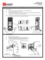
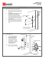
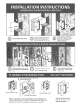
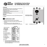
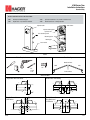
4700 Series Trim
Installation Instructions
Standard Duty
DEVICES COVERED IN THESE INSTRUCTIONS:
47DT
47NL
Dummy-Pull When Dogged
Night Latch - Key Retracts Latchbolt
47CE
47BE
Cylinder Escutcheon - Key Locks & Unlocks Lever
Blank Escutcheon - Always Operable
47CE shown
Cylinder collar
Cylinder locking plate
Cylinder cam
Trim actuating shaft
Mounting posts
Handing pin
Lever handle
TOOLS
Machine Screws
Tools Required
Door Handing
Outside of Door
LHR
RHR
1/2”
1-3/32”
1-1/4”
1/4” - 20
Inside of Door
APPLICATIONS
Single Door with Rim Device
Double Door with Mullion
CL
CL
Door
Door
Door
Rim Exit Device
Rim Exit Device
Mullion
2-1/4”
[57]
CL
1-7/16”
[37]
Door
Door
Surface Vertical Rod Exit Device
1-7/16”
[37]
2-1/4”
[57]
09.08
Rim Exit Device
2-1/4”
[57]
2-1/4”
[57]
2-1/4”
[57]
Double Door with
SVR Device
CL
CL
Surface Vertical Rod Exit Device
Vertical Rods
Double Door with
Rim Device and
SVR Device
CL
CL
Double Door Strike
Door
Door
Rim Exit Device
Surface Vertical Rod Exit Device
2-3/4”
[70]
2-3/4”
[70]
1 of 3
4700 Series Trim
Installation Instructions
Standard Duty
INSTRUCTIONS
1.
Set trim handing.
A.
B.
C.
Rotate lever handle to the right or left direction to match desired door handing.
Insert square handing pin into hub as shown.
For Surface Vertical Rod devices only, be sure the handing matches what is indicated on the product box label.
Surface Vertical Rod handing cannot be changed in the field.
Note:
See back of trim for a label that indicates which direction to position handle for RHR or LHR handing. The label
also indicates which direction the trim actuating shaft should rotate.
RHR
(Not applicable on
Rim devices)
LHR
Right Hand Reverse
(RHR)
Left Hand Reverse
(LHR)
(Not applicable on
Rim devices)
Hub
Step 1A: Door Handing
Square Handing Pin
Step 1B: Insert Square Handing Pin
2.
Install mortise cylinder.
A.
B.
C.
D.
Remove key from mortise cylinder.
Slide wave washer and cylinder collar onto mortise cylinder body.
Screw mortise cylinder into escutheon trim with cam position as shown.
Install cylinder locking plate and use provided screws to secure.
Wave Washer
Cylinder Collar
Position Cam pointing up
Mortise Cylinder
Cylinder
Locking
Plate
Mortise Cylinder
Step 2B & 2C:
Install Mortise Cylinder
09.08
Step 2D: Install Cylinder Locking Plate
2 of 3
4700 Series Trim
Installation Instructions
Standard Duty
INSTRUCTIONS (CONTINUED)
3.
Mark and drill mounting holes for escutcheon trim.
A.
B.
C.
D.
Mark horizontal centerline by matching it to exit
device centerline, which can be found on push
side of door.
Apply template to door using centerline. Refer
to Applications section on page one to
determine location of vertical centerline.
Trim actuator shaft hole
Vertical centerline should match exit device
Ø 1/2”
vertical centerline located on push side of door.
Mark and drill 1/2” holes for mounting posts as
shown on template.
Mark and drill 1/2” hole for trim actuator shaft,
which mates with exit device (not required for
47DT). See exit device instructions for further
2-7/8”
details.
[73]
Trim
mounting
holes
Ø 1/2”
See page one for details on
your specific application
4.
Install escutcheon trim.
A.
B.
C.
D.
Note:
Insert trim mounting posts and
actuating shaft through door.
Mate trim actuating shaft with
cam on back of exit device.
Secure from push side of door
with provided 1/4” - 20 screws.
Test installation by rotating lever
handle or key to verify trim
activates exit device.
Trim actuating shaft
Door
Exit device mounting
holes
Dummy trim is only for pulling
door. The handle does not rotate.
Cam mates with trim
actuating shaft
09.08
3 of 3