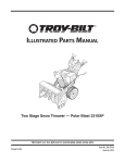
1
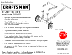
PROFESSIONAL GRADE
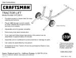
TRACTOR L I F T
TL 4 0 0 0
Easily change belts, blades
and service front & rear tires
Tractor Lift can be used out of the box on most tractor
brands available through major retailers. Tractor Lift
mounting hardware is provided if your tractor does not
have a bumper or brush guard.
Maintenance
Store in a clean dry place.
Recommended tire pressure - 30 PSI.
Before each use:
Always check tire pressure.
Always inspect unit for damage.
Always check fasteners for tightness.
Tools required for assembly:
1. 9/16” wrench and/or socket
2. Adjustable wrench
3. Pliers
*Patent Pending
If there are any missing parts, or if you have any
questions on assembly, operation, maintenance or
safety, please call 800-652-2321
WARNINGS
• Always use the stabilizer bar provided when using tractor lift.
• Make sure stabilizer bar is properly in place before starting any work on
tractor.
• Read and understand all safety and operating instructions before using
the tractor lift. Never allow anyone unfamiliar with these instructions to
use the tractor lift.
• Read and understand all safety and operating instructions provided by
the tractor's manufacturer before using tractor lift.
• Never lay under the tractor or mowing deck.
• When using lift, keep all bystanders, including children, away.
• This tractor lift must be only used for lifting and lowering to and from a
level and stable surface.
• Never use in wet conditions.
• Do not attempt to lift the front and back of the tractor at the same time.
• Do not use tractor lift as an automotive lift, or for any other use for which
it is not intended or designed.
• If tractor lift is bowing while lifting or lowering your tractor, which
indicates an overload condition, remove the tractor immediately.
• Do not attempt to lift or lower any power equipment while motor is
running.
• Never engage blades while using tractor lift.
• Always disconnect spark plug wire from tractor before beginning any
work on tractor.
• Do not exceed the rated capacity of the tractor lift - 270#.
• Failure to follow these warnings may result in property damage and/or
serious bodily injury.
Made in China
SAFETY INSTRUCTIONS
• Be sure to read and follow all safety instructions and warnings. Failure to
follow these instructions may result in damage to the product and/or
serious personal injury.
• Danger of serious personal injury exists. Serious personal injury can
occur when using a lifting device.
• Never attempt to ride any vehicle up or down the tractor lift.
• Do not climb onto tractor while tractor is in the elevated position.
• When working on the front of the tractor always place wheel chocks in
back of the rear wheels/tires.
• Always raise and lower tractor lift in a controlled fashion; do not allow
the tractor to drop too quickly, damage could occur.
• Make sure lifting arms are aligned and set to the proper distance apart
so that the equipment being loaded is well balanced on the lift.
• Do not remove warning decals from product.
• Before each use, always check for any worn, loose, or damaged parts on
the tractor lift. If any damage is present, DO NOT USE THE TRACTOR LIFT.
• Periodically check the fasteners to make sure they are still tight and in
place.
• Keep lift surface clean by occasionally cleaning with water and any mild
detergent.
• Do not add to or try to modify the tractor lift in any way. Any modifications will void any warranties.
• Failure to abide by the warnings and read the safety instructions may
result in loss of load, damage to lift and/or property, serious personal
and/or fatal injury.
310042-REV C
1/09
CARTON CONTENTS
8
11
3
2
1
5
7R
7L
4
6
10A
TOOLS REQUIRED FOR ASSEMBLY
MAINTENANCE
9/16" Wrench and/or Socket
Adjustable wrench
Pliers
Store unit in a clean dry place.
Recommended tire pressure - 30 PSI.
Before each use:
Always check tire pressure.
Always inspect unit for damage.
Always check fasteners for tightness.
Page 2
10B
HARDWARE CONTENTS - BAG #1
22
24
30
23
25
39
HARDWARE CONTENTS - BAG #2
29
27
35
36
24
34
26
HARDWARE CONTENTS - BAG #1
28
32
HARDWARE CONTENTS - BAG #2
Page 3
31
Assemble Tractor Lift
Attach Lift Tubes to Angle Frame
•
Attach Receiver Tubes ( 4 ) to angle frame ( 1 ) using bolts ( 22 ), flat washers ( 24 ), split lock
washers ( 23 ) and hex nuts ( 25 ).
•
Slide Lift Arm Tubes (5) into Receiver Tubes (4) secure with Ring Grip Pins (30).
Note: Over-tightening receiver bolts ( 22 ) could cause damage to lift tubes ( 4 ).
1
22
30
24
4
23
25
5
NOTE: Tractor lift is width adjustable. For all tractors, the lifting
claws will engage lifting bar similar to STEP 1 on page 9.
Page 4
Assemble Tractor Lift
Attach Handle to Angle Frame
Step 1.
Attach handle bottom ( 3 ) to angle frame ( 1 ) using hex bolt ( 22 ),
flat washer ( 24 ), split lock washer ( 23 ) and hex nut (25 ).
Step 2.
Insert ring grip pin ( 30 ), as shown.
Step 3.
Insert handle top ( 2 ) into handle bottom ( 3 ). Secure with hex
bolts ( 29 ) and split lock washers ( 23 ).
Step 4.
Slide stabilizer bar (8) onto Foot Bar Tube. Insert hex bolt (22)
and flat washer (24) through side of handle top (2). Tighten
using split lock washer (23) and hex nut (25).
Step 5.
Align hole in stabilizer bar (8) with hex bolt (22).
Tighten using wing nut (39).
22
24
25
23
30
1
29
3
23
8
24
25
22
24
1
Page 5
39
Installing Front Lift Brackets
(if tractor is equipped with a tube style bumper, then this step is not required)
1
2
Refer to pages 7-8 for specific tractor models.
Slide lifting bracket onto existing shoulder bolt.
Remove self-tapping screw with 9/16” socket. Align
hole in bracket with hole in tractor frame. Replace
self-tapping screw. Repeat for opposite side.
Slide lifting bar through both lifting brackets.
3
4
When lifting bar is through both brackets, push hair
pin cotter through holes found in lifting bar. This will
keep lifting bar from sliding out of brackets.
This is how the tractor should look when installation
is complete.
Installing Rear Lift Bar
5
Remove hair pin cotter from
lifting bar. Slide bar out of lifting
brackets.
6
7
Remove nut and washer from
threaded stud. Slide threaded
stud through hitch pin hole.
Replace nut and washer.
Page 6
Tighten nut with a 3/4” wrench. Installation is now complete.
Tractor Specific Installation
Tractor Lift can be used out of the box on any tractor equipped with a tubular front bumper or brushguard. If your tractor does not have a
bumper or brush guard, please read the configuration legend and follow the steps below for your model of tractor:
2
A
29
24
1
3
456
CONFIGURATION LEGEND:
29
For the different models of tractors, different holes
in the tractor bracket will be used. To help understand
the appropriate configuration for your type of tractor,
the legend represents all the holes as numbers with
the addition of the letter A as the slot.
26
29
24
7R
6
JOHN DEERE
27
26
7R
6
26
7L
HUSQVARNA
7L
27
MODEL:
LA100 SERIES
R.
•
Insert bolt ( 29 ) through inside front hole of frame, through #1
hole in tractor bracket ( 7 ) and secure with nyloc nut ( 27 ).
•
Insert bolt (29) through inside back hole of frame, through
slot A in tractor bracket (7), add washer (24) and secure with
nyloc nut (27).
•
Refer back to STEP 2 on page 6 of the Assembly Guide.
27
29
MODELS:
LTH1538
YTH2042
YTH2246
YTH20K46
26
27
R.
•
Insert bolt ( 29 ) through inside front hole of frame, through #4 hole
in tractor bracket ( 7 ) and secure with nyloc nut ( 27 ).
•
Insert bolt (29) through inside back hole of frame, through slot A in
tractor bracket (7), add washer (24) and secure with nyloc nut (27).
•
Refer back to STEP 2 on page 6 of the Assembly Guide.
Husqvarna R. is a registered trademark of Husqvarna AB, LLC.; John Deere is a registered trademark of Deere and Company.
Page 7
Continue...
26
36
26
34
"X"
7R
7R
CUB CADET
7L
WHITE OUTDOOR ,HUSKEE , HUSKEE SUPREME ,
TORO , TROY BILT , YARD MACHINE
R.
R.
R.
26
R.
R.
R.
R.
•
Insert bolt (40) through #2 hole in tractor bracket (7), through
outside front hole of frame, and secure with nyloc nut (41).
•
Insert bolt (40) with washer (42) through Slot A in tractor
bracket (7), through outside back hole of frame, and secure
with nyloc nut (41).
•
Refer back to STEP 2 on page 6 of the Assembly Guide.
26
6
7L
MODEL:
LT1000 SERIES
Step 1:
•
Using Slot A, slide tractor bracket (7) onto existing
shoulder bolt ("X")
7R
36 34
6
"Z"
7L
Step 2:
•
Remove 1/2" screw bolt ("Z"). Align #2 hole in tractor
bracket (7) with threaded hole in frame, replace screw
bolt and tighten to frame. If tractor does not have Bolt "Z",
use supplied 3/8" x 1-1/2 Self Threading bolt (28)
•
Refer back to STEP 2 on page 6 of the Assembly Guide.
Cub Cadet R. , Troy Bilt R. , White Outdoor R. , and Yard Machine R. are registered trademarks of MTD Products, Inc.
Page 8
Lifting Your Tractor (front)
1
2
Engage lifting claws to lift bar
Place foot onto footbar while keeping lifting claws
engaged to lift bar.
4
3
A. Apply slow continuous pressure to foot bar while
bringing the handle towards the ground.
B. While applying pressure with foot, bring the
handle slowly towards the ground.
The tractor lift is securely in place when the curve in
the handle is resting flat on the ground.
6
5
Remove wingnut from stabilizer holder bolt.
Slide stabilizer bar off footbar. Replace wingnut.
Rotate stabilizer bar so stabilizer bar foot pad is
resting on the ground. Slide stabillizer bar back onto
footbar. Stabilizer bar should properly be in place
under the tractor.
Page 9
Service Parts List
2
37
37
39
8
25
23
31
26
38
24 22
11
32
26
23
33
3
6
38
38
10A
23
7L
38
1
30 22
30
7R
25
20
22
30
24
23
4
5
Page 10
25
9
24
21
10B