1
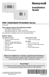
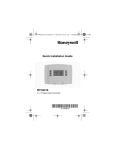
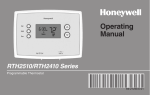
Quick Installation Guide
RTH2510/RTH2410 Series
Programmable Thermostat
69-2726ES_A.indd 1
69-2726ES-02
5/4/12 11:33 AM
Identify System Type
This thermostat is compatible with the following systems:
Gas, oil or electric furnace
Central air conditioner
Hot water system with or without pump
Millivolt system
Central heating and cooling system
Heat pump without auxiliary/backup heat
Heat pump with auxiliary/backup heat
Do you need assistance?
We are here to help.
Call 1-800-468-1502 for wiring
assistance before returning
the thermostat to the store.
This thermostat cannot be used on multistage systems.
69-2726ES—02ii
69-2726ES_A.indd 2
5/4/12 11:33 AM
1
Turn Off Power to Heating/
Cooling System
OFF
or
69-2726ES_A.indd 1
169-2726ES—02
5/4/12 11:33 AM
2
Remove Old Thermostat
Remove old thermostat but leave wallplate with
wires attached.
Do not remove
wallplate yet
Is there a sealed tube containing
mercury? If so, see back cover for
proper disposal instructions.
EM. HEAT AUX. HEAT
50 60 70 80
50 60 70 80 F
Old thermostat
EM. HEAT
AUTO
OFF
M33835
Cover
69-2726ES—022
69-2726ES_A.indd 2
5/4/12 11:33 AM
3
Label Wires with Tags
Label the wires using the supplied wire labels as you
disconnect them.
M28100
Wire Labels
M33763
69-2726ES_A.indd 3
369-2726ES—02
5/4/12 11:33 AM
4
Separate Wallplate from
New Thermostat
Remove wallplate from the new thermostat and mount onto
wall.
TO REMOVE WALLPLATE
PULL HERE
M32731
Wallplate
69-2726ES—024
69-2726ES_A.indd 4
5/4/12 11:33 AM
5
Mount Wallplate
Mount the new wallplate using the included screws
and anchors.
W/
Aux
Not
Used
M32714
Drill 3/16-in. holes for drywall
Drill 3/32-in. holes for plaster
69-2726ES_A.indd 5
569-2726ES—02
5/4/12 11:33 AM
6
Connect Wires
Simply match wire labels.
WIRE
HOLE
G
INSERT WIRES
AND TIGHTEN
SCREWS
R
Y W
SCREW
W/
Aux
LABELED
WIRES
Not
Used
M32715
Remove metal jumper if you have both R and Rc wires.
Labels don’t match? See page 22.
Have a Heat Pump system? See page 23.
We are here to help.
Call 1-800-468-1502 for wiring assistance.
69-2726ES—026
69-2726ES_A.indd 6
5/4/12 11:33 AM
7
Install Batteries
Install two AAA alkaline batteries.
RTHXXXX
M32707
Back of thermostat
69-2726ES_A.indd 7
769-2726ES—02
5/4/12 11:33 AM
8
Set fan operation switch
Move the switch to the proper setting:
Gas or Oil: For gas or oil heating systems, leave the fan
operation switch in this factory-set position (for systems that
control the fan in a call for heat).
Electric or Heat Pump: Change the switch to this setting
for heat pump or electric heat systems. (This setting is for
systems that allow the thermostat to control the fan in a call
for heat, if a fan wire is connected to the G terminal.)
RTHXXXX
GAS OR OIL
ELECTRIC OR HEAT PUMP
GAS OR OIL
ELECTRIC OR HEAT PUMP
M32716
69-2726ES—028
69-2726ES_A.indd 8
5/4/12 11:33 AM
9
Install Thermostat onto Wallplate
Install thermostat onto the wallplate on the wall.
W/
Aux
Not
Used
Set
Hold
Run
Heat Off Cool
Heat Off Cool
Fan
Fan
Auto On
Auto On
M33592
69-2726ES_A.indd 9
969-2726ES—02
5/4/12 11:33 AM
10
Turn Power Back On
Turn the power back on to the heating/cooling system.
ON
or
69-2726ES—0210
69-2726ES_A.indd 10
5/4/12 11:33 AM
11
If your system type is...
If your system type is:
q Single Stage Heat and Cool
q Heat Only or Cool Only
Congratulations, you’re done!
If your system type is:
q Heat Pump* with Backup Heat
Continue with advanced installation
on next page to match your thermostat to your system
type.
*Heat Pump—an air conditioner that provides cooling in the
summer, and also runs in reverse in the winter to provide
heating.
If you are not sure of your system type or if you have
other questions, call us toll-free at 1-800-468-1502.
This thermostat works on 24 volt or 750 mV systems. It will
NOT work on multi-stage conventional systems or 120/240
Volt systems.
1169-2726ES—02
69-2726ES_A.indd 11
5/4/12 11:33 AM
Advanced Installation
Enter system setup...............................................................13
Changing settings.................................................................14
System type..........................................................................15
Heating cycle rate.................................................................16
Early start.............................................................................17
Temperature display.............................................................18
Compressor protection.........................................................19
Clock display........................................................................20
Restore program schedule default.......................................21
Wiring conventional system..................................................22
Wiring heat pump.................................................................23
Troubleshooting....................................................................25
Customer assistance............................................................26
Limited warranty...................................................................27
69-2726ES_A.indd 12
5/4/12 11:33 AM
RTH2510/RTH2410
System setup
Enter System Setup
SETUP
To enter system setup, press and hold both the s and
t buttons until the display changes (approximately 5
seconds).
WIRING
Set
Hold
Run
Fan
Fan
Auto On
Auto On
M33593
ASSISTANCE
Heat Off Cool
Heat Off Cool
TROUBLESHOOTING
1369-2726ES—02
69-2726ES_A.indd 13
5/4/12 11:33 AM
Advanced Installation Guide
SETUP
System setup
Changing Settings
See pages 15–21 to change Function Settings.
Function
Set
WIRING
Hold
Run
1
0
M33594
Change Function
ASSISTANCE
Setting
Change Setting
1. Press the s or t button to change the setting.
2. Press the s and t buttons simultaneously for one
second to advance to the next function.
TROUBLESHOOTING
3. Press the Run button to exit and save settings.
NOTE: If you do not press any button for 60 seconds while
you are in the setup menu, the thermostat automatically
saves any changes made and exits the menu.
69-2726ES—0214
69-2726ES_A.indd 14
5/4/12 11:33 AM
RTH2510/RTH2410
System setup
Function 1: System Type
SETUP
1
0
M32718
Press the s or t button to select the type of Heat/Cool
system you have in your home.
When finished,
press s and t
to advance to the
next function.
AND
TROUBLESHOOTING
OR
Press to
change
setting.
ASSISTANCE
1 Heat pump with auxiliary/backup heat: Outside
compressor provides both heating and cooling.
WIRING
0 Heating & cooling: Gas, oil or electric heating with
central air conditioning or heat pump without auxiliary/
back-up heat.
M33591
1569-2726ES—02
69-2726ES_A.indd 15
5/4/12 11:33 AM
Advanced Installation Guide
System setup
SETUP
Function 5: Heating cycle rate
WIRING
5
5
M32720
ASSISTANCE
5 Gas or oil furnace: Use this setting if you have a
standard gas or oil furnace that is less than 90%
efficient.
6 Electric furnace: Use this setting if you have any type
of electric heating system.
3 Hot water or high-efficiency furnace: Use this
setting if you have a hot water system or a gas furnace
of greater than 90% efficiency.
TROUBLESHOOTING
2 Gas/oil steam or gravity system: Use this setting if
you have a steam or gravity heat system.
Press the s or t button to select your heating system
and optimize its operation.
OR
Press to
change
setting.
When finished,
press s and t
to advance to the
next function.
AND
M33591
69-2726ES—0216
69-2726ES_A.indd 16
5/4/12 11:33 AM
RTH2510/RTH2410
System setup
Function 13: Early Start
SETUP
13 1
WIRING
M32721
1 On
0 Off
OR
Press to
change
setting.
When finished,
press s and t
to advance to the
next function.
AND
TROUBLESHOOTING
Press the s or t button to select Early Start.
ASSISTANCE
Early start allows the heating or cooling to turn
on before the program start time, so the temperature is reached at the time you set. Simply
program the desired times and temperature
into the schedule. The thermostat will turn the
heating or cooling on early so that the desired
temperature is reached at the desired time.
M33591
1769-2726ES—02
69-2726ES_A.indd 17
5/4/12 11:33 AM
Advanced Installation Guide
System setup
SETUP
Function 14: Temperature display
14 0
WIRING
M32722
0 Fahrenheit temperature display (°F)
TROUBLESHOOTING
ASSISTANCE
1 Celsius temperature display (°C)
Press the s or t button to select Fahrenheit or Celsius
temperature display.
OR
Press to
change
setting.
When finished,
press s and t
to advance to the
next function.
AND
M33591
69-2726ES—0218
69-2726ES_A.indd 18
5/4/12 11:33 AM
RTH2510/RTH2410
System setup
Function 15: Compressor Protection
SETUP
15 1
M32723
WIRING
1 On
0 Off
OR
Press to
change
setting.
When finished,
press s and t
to advance to the
next function.
AND
TROUBLESHOOTING
Press the s or t button to select Compressor Protection
settings.
ASSISTANCE
Compressor Protection: This feature forces the compressor to wait approximately 5 minutes before restarting,
to prevent equipment damage. During the wait time, the
message “Cool On” or “Heat On” is displayed on screen.
M33591
1969-2726ES—02
69-2726ES_A.indd 19
5/4/12 11:33 AM
Advanced Installation Guide
System setup
SETUP
Function 20: Clock Display
20 0
WIRING
M32724
0 12-hour display
TROUBLESHOOTING
ASSISTANCE
1 24-hour display
Press the s or t button to select clock display.
OR
Press to
change
setting.
When finished,
press s and t
to advance to the
next function.
AND
M33591
69-2726ES—0220
69-2726ES_A.indd 20
5/4/12 11:33 AM
RTH2510/RTH2410
System setup
Function 21: Change Filter Timer
SETUP
21
0
M33631
WIRING
0Off
1 30 days
2 90 days
ASSISTANCE
3 6 months
4 9 months
5 1 year
OR
Press to
change
setting.
When finished,
press s and t
to advance to the
next function.
AND
TROUBLESHOOTING
Press the s or t button to select Change Filter Timer.
M33591
2169-2726ES—02
69-2726ES_A.indd 21
5/4/12 11:33 AM
Advanced Installation Guide
System setup
SETUP
Function 40: Restore Program Schedule to Default
40 0
WIRING
M32725
0 Off
TROUBLESHOOTING
ASSISTANCE
1 On - Program schedule default settings are listed in
the operating manual.
Press the s or t button to select restore program schedule to default settings.
OR
Press to
change
setting.
When finished,
press Run to
exit and save
changes.
M33595
69-2726ES—0222
69-2726ES_A.indd 22
5/4/12 11:33 AM
RTH2510/RTH2410
About your new thermostat
Wiring—Conventional
System
4
4
SETUP
If labels do not match letters on the thermostat, check the
chart below and connect to terminal as shown here (see
notes, below).
WIRING
O
G
Y
W/ NOT R
AUX USED
Rc
M32726
If wires will be connected to both R and Rc terminals,
remove metal jumper (see page 6).
Do not use C or X. Wrap bare end of wire with
electrical tape.
Place a jumper (piece of wire) between Y and W/Aux
if you are using a heat pump without auxiliary/backup
heat.
TROUBLESHOOTING
If you have a heat pump without auxiliary/backup heat
connect O or B, not both. If you do not have a heat
pump, do not connect B. Wrap bare end of wire with
electrical tape.
ASSISTANCE
B
2369-2726ES—02
69-2726ES_A.indd 23
5/4/12 11:33 AM
Advanced Installation Guide
About your new
Wiring—Heat
Pump
thermostat
SETUP
Connect wires: Heat Pump
1. Match each labeled wire with same letter on new
thermostat.
2. Use a screwdriver to loosen screws, insert wires into
hole under screw, then tighten screws until wire is
secure.
TROUBLESHOOTING
ASSISTANCE
WIRING
3. Push any excess wire back into the wall opening.
O
G Y Aux
B O G
Y W/
AUX
R
R Rc
M32727
Labels don’t match? See page 24.
Wiring complete, return to Step 7.
69-2726ES—0224
69-2726ES_A.indd 24
5/4/12 11:33 AM
RTH2510/RTH2410
About your new
Wiring—Heat
Pump
thermostat
If labels do not match letters on the thermostat, check the
chart below and connect to terminal as shown here (see
notes, below).
1
4
7
5
3
L
E
C
B
F
X
X2
O
G
H
X
B
Y
F
O
G
Y1
M
Y
R
AUX
W
W1
W2
NOT
W/
AUX USED
RC
V
VR
R
Rc
2
M32728
ASSISTANCE
B
2
7
WIRING
6
SETUP
Alternate wiring (for heat pumps with auxiliary or
backup heat only)
Leave metal jumper in place, connecting R & Rc terminals.
If your old thermostat had both V and VR wires, stop now and contact a
qualified contractor for help.
If your old thermostat had Y1, W1 and W2 wires, stop now and
contact a qualified contractor for help.
5
Do not use C or X wire. Do not use B wire if you already have O wire.
Wrap bare end of wire with electrical tape.
6
Do not use L wire. Wrap bare end of wire with electrical tape.
7
If your old thermostat had E and Aux wires (or alternate wires),
connect both wires to Aux terminal.
TROUBLESHOOTING
If your old thermostat had separate O and B wires, wrap the B wire in
electrical tape and do not connect.
Wiring complete, return to Step 7.
2569-2726ES—02
69-2726ES_A.indd 25
5/4/12 11:33 AM
Advanced Installation Guide
If you have difficulty with your thermostat, please try the
following suggestions. Most problems can be corrected
quickly and easily.
Display is blank • Make sure furnace door is closed
securely.
• Make sure fresh AAA alkaline
batteries are correctly installed
(see page 7).
Heating or
• Set System switch to Heat. Make
cooling system
sure the temperature is set higher
does not
than the Inside temperature.
respond
• Set System switch to Cool. Make
sure the temperature is set lower
than the Inside temperature.
• Check circuit breaker and reset if
necessary.
• Make sure heating & cooling power
switches are on.
• Make sure furnace door is securely
closed.
• Wait 5 minutes for the system to
respond.
TROUBLESHOOTING
ASSISTANCE
WIRING
SETUP
Troubleshooting
69-2726ES—0226
69-2726ES_A.indd 26
5/4/12 11:33 AM
RTH2510/RTH2410
Troubleshooting
“Heat On” is
not displayed
• Set the System switch to Heat, and
set the temperature level above the
current room temperature.
“Cool On” is
not displayed
• Set the System switch to Cool, and
set the temperature level below the
current room temperature.
ASSISTANCE
• Compressor protection feature is
engaged. Wait 5 minutes for the
system to restart safely, without
damage to the compressor.
WIRING
“Cool On” or
“Heat On” is
flashing
SETUP
Temperature
Make sure heating and cooling
settings do not temperatures are set to acceptable
change
ranges:
• Heat: 40° to 90°F (4.5° to 32°C).
• Cool: 50° to 99°F (10° to 37°C).
Customer assistance
TROUBLESHOOTING
For assistance with this product, please visit
http://yourhome.honeywell.com or call Honeywell
Customer Care toll-free at 1-800-468-1502.
2769-2726ES—02
69-2726ES_A.indd 27
5/4/12 11:33 AM
MERCURY NOTICE: Do not place your old
thermostat in the trash if it contains mercury in a
sealed tube. Contact the Thermostat Recycling
Corporation at www.thermostat-recycle.org or 800238-8192 for information on how and where to
properly and safely dispose of your old thermostat.
CAUTION: To avoid possible compressor damage,
do not run air conditioner if the outside temperature
drops below 50°F (10°C).
Automation and Control Solutions
Honeywell International Inc.
1985 Douglas Drive North
Golden Valley, MN 55422
http://yourhome.honeywell.com
® U.S. Registered Trademark
© 2012 Honeywell International Inc.
69-2726ES—02 M.S. 05-12
Printed in Mexico
69-2726ES_A.indd 28
5/4/12 11:33 AM
Guía de instalación rápida
Serie RTH2510/RTH2410
Termostato programable
69-2726ES_A.indd 1
69-2726ES-02
5/4/12 11:33 AM
Identifique el tipo de sistema
Este termostato es compatible con los siguientes sistemas:
Calefactor a gas, aceite o eléctrico
Aire acondicionado central
Sistema a agua caliente con o sin bomba
Sistema de milivoltios
Calefacción y aire acondicionado centrales
Bomba de calor sin calefacción auxiliar
Bomba de calor con calefacción auxiliar
¿Necesita ayuda?
¡Aquí estamos!
Llame al 1-800-468-1502 para
obtener asistencia con el
cableado antes de devolver el
termostato a la tienda.
Este termostato no puede usarse en sistemas
multietapas
69-2726ES—02ii
69-2726ES_A.indd 2
5/4/12 11:33 AM
1
Desconecte la alimentación
en el sistema de calefacción/
refrigeración
APAGADO
o
69-2726ES_A.indd 1
169-2726ES—02
5/4/12 11:33 AM
2
Remueva su viejo termostato
Retire el termostato existente pero deje la placa de montaje
con los cables adheridos.
No retirar la placa
mural todavía
¿Hay un tubo sellado que
contiene mercurio? Si es así,
consulte en la cubierta de este
manual las instrucciones para
su desecho apropiado.
EM. HEAT AUX. HEAT
50 60 70 80
50 60 70 80 F
Termostato viejo
EM. HEAT
AUTO
OFF
Cubierta
M33835
69-2726ES—022
69-2726ES_A.indd 2
5/4/12 11:33 AM
3
Identifique los cables
Identifique los cables a medida que los desconecta,
utilizando las etiquetas que se suministran.
M28100
Rótulos para los cables
M33763
69-2726ES_A.indd 3
369-2726ES—02
5/4/12 11:33 AM
4
Separe la placa de montaje del
termostato nuevo
Retire la placa de montaje del termostato nuevo y móntela
en la pared.
TO REMOVE WALLPLATE
PULL HERE
M32731
Placa de montaje
69-2726ES—024
69-2726ES_A.indd 4
5/4/12 11:33 AM
5
Coloque la placa de montaje
Monte la nueva placa de montaje utilizando los tornillos y
anclajes que se suministran.
W/
Aux
Not
Used
M32714
Taladre agujeros de 3/32 in. (2,4 mm) en yeso
Taladre agujeros de 3/16 in. (4,8 mm) en paneles de yeso
69-2726ES_A.indd 5
569-2726ES—02
5/4/12 11:33 AM
6
Conecte los cables
Simplemente haga corresponder las etiquetas de los cables.
ORIFICIO DE
CABLEADO
G
INSERTE
LOS CABLES
YAPRIETE
LOS TORNILLOS
TORNILLO
R
Y W
W/
Aux
CABLES
ETIQUETADOS
Not
Used
MS32715
Retire el empalme metálico si tiene los cables “R” y “Rc”.
¿Los rótulos no coinciden? Vea la página 22.
¿Tiene un sistema de bomba de calor? Ver página 23.
Estamos aquí para ayudarle.
Llame al 1-800-468-1502 para asistencia con el cableado.
69-2726ES—026
69-2726ES_A.indd 6
5/4/12 11:33 AM
7
Instale las baterías
Instale dos baterías alcalinas AAA.
RTHXXXX
M32707
Parte de atrás del termostato
69-2726ES_A.indd 7
769-2726ES—02
5/4/12 11:33 AM
8
Configure el interruptor de
funcionamiento del ventilador
Mueva el interruptor a la configuración adecuada:
Gas o aceite: para los sistemas de calefacción de gas o
aceite, deje el interruptor del ventilador en esta posición
configurada de fábrica (para sistemas que controlan el
ventilador en una orden de calefacción).
Eléctrico o bomba de calor: cambie el interruptor a
esta configuración para sistemas de bomba de calor o de
calefacción eléctrica. (Esta configuración es para sistemas
que permitan que el termostato controle el ventilador en
una orden de calefacción, si un cable del ventilador está
conectado al terminal G).
RTHXXXX
GAS OR OIL
ELECTRIC OR HEAT PUMP
GAS OR OIL
ELECTRIC OR HEAT PUMP
M32716
69-2726ES—028
69-2726ES_A.indd 8
5/4/12 11:33 AM
9
Instale el termostato en la placa de
montaje
Instale el termostato en la placa de montaje en la pared.
W/
Aux
Not
Used
Set
Hold
Run
Heat Off Cool
Heat Off Cool
Fan
Fan
Auto On
Auto On
M33592
69-2726ES_A.indd 9
969-2726ES—02
5/4/12 11:33 AM
10
Active nuevamente el suministro
eléctrico
Active nuevamente el suministro eléctrico del sistema de
calefacción/aire acondicionado.
ENCENDIDO
o
69-2726ES—0210
69-2726ES_A.indd 10
5/4/12 11:33 AM
11
Si su tipo de sistema es...
Si su tipo de sistema es:
q Calor y frío de una sola etapa
q Calefacción únicamente o Refrigeración únicamente
¡Felicitaciones, ya está listo!
Si su tipo de sistema es:
q Bomba de calor* con calor de respaldo
Continúe con la instalación avanzada
en la próxima página para adaptar el termostato a su tipo
de sistema.
*Bomba de calor —un acondicionador de aire que
proporciona enfriamiento en el verano y también funciona en
reversa en el invierno, proporcionando calor.
Si no está seguro del tipo de sistema que tiene o si
tiene otras preguntas, llámenos gratis al
1-800-468-1502.
Este termostato funciona con sistemas de 24 voltios o 750
mV. NO funcionará con sistemas convencionales de etapas
múltiples ni con sistemas de 120/240 voltios.
1169-2726ES—02
69-2726ES_A.indd 11
5/4/12 11:33 AM
Guía de instalación avanzada
Ingrese la configuración del sistema....................................13
Cómo cambiar la configuración............................................14
Tipo de sistema....................................................................15
Frecuencia del ciclo de calefacción......................................16
Encendido anticipado...........................................................17
Indicador de temperatura.....................................................18
Protección del compresor.....................................................19
Visualizador del reloj............................................................20
Restablecimiento del cronograma del
programa a la configuración predeterminada......................21
Cableado sistemas convencionales.....................................22
Cableado bomba de calor....................................................23
En caso de dificultades........................................................25
Asistencia al cliente..............................................................26
Garantía limitada..................................................................27
69-2726ES_A.indd 12
5/4/12 11:33 AM
RTH2510/RTH2410
Configuración del sistema
Para ingresar la configuración del sistema, presione
y mantenga presionados los botones s (arriba) y t
(abajo) hasta que el visualizador cambie (5 segundos
aproximadamente).
CONFIGURACIÓN
Ingrese la configuración del sistema
WIRING
Set
Hold
Run
Fan
Fan
Auto On
Auto On
M33593
ASSISTANCE
Heat Off Cool
Heat Off Cool
TROUBLESHOOTING
1369-2726ES—02
69-2726ES_A.indd 13
5/4/12 11:33 AM
Guía de instalación avanzada
CONFIGURACIÓN
Configuración del sistema
Cómo cambiar la configuración
Consulte las páginas 15-21 para cambiar la configuración
de las funciones.
Set
Hold
WIRING
ASSISTANCE
Configuración
Función
Run
1
0
M33594
Cambio de
función
Cambio de
configuración
1. Presionar s o t para cambiar la configuración.
2. Presionar s y t al mismo tiempo por un segundo
para ir a la función siguiente.
TROUBLESHOOTING
3. Presione el botón Run para salir y guardar los
cambios.
NOTA: si no se presiona ningún botón durante 60
segundos mientras esté abierto el menú de configuración,
el termostato salvaguarda los cambios automáticamente y
sale del menú.
69-2726ES—0214
69-2726ES_A.indd 14
5/4/12 11:33 AM
RTH2510/RTH2410
Configuración del sistema
CONFIGURACIÓN
Función 1: Tipo de sistema
1
0
M32718
Presione el botón s o t para elegir el tipo de sistema
de calefacción/refrigeración que tenga en su hogar.
Cuando termine,
presione s y t
para avanzar
hasta la siguiente
función.
Y
TROUBLESHOOTING
O
Presione
para
cambiar la
configuración
ASSISTANCE
1 Bomba de calor con calefacción auxiliar/de
reserva: el compresor externo proporciona tanto
calefacción como refrigeración.
WIRING
0 Calefacción y refrigeración: calefacción de gas,
aceite o eléctrica con aire acondicionado central o
bomba de calor sin calefacción auxiliar/de reserva.
MS33591
1569-2726ES—02
69-2726ES_A.indd 15
5/4/12 11:33 AM
Guía de instalación avanzada
CONFIGURACIÓN
Configuración
del
sistema
About your new
thermostat
Función 5: Frecuencia del ciclo de calefacción
5
5
TROUBLESHOOTING
ASSISTANCE
WIRING
M32720
5 Sistema de calefacción de gas o aceite: utilice
esta configuración si tiene un sistema de calefacción
estándar de gas o aceite cuyo rendimiento sea inferior
al 90%.
6 Sistema de calefacción eléctrico: utilice esta
configuración si tiene cualquier tipo de sistema de
calefacción eléctrica.
3 Sistema de calefacción de agua caliente o de alto
rendimiento: utilice esta configuración si tiene un
sistema de agua caliente o de calefacción de gas cuyo
rendimiento sea superior al 90%.
2 Sistema de vapor o de gravedad a gas/aceite:
utilice esta configuración si tiene un sistema de
calefacción de vapor o gravedad.
Presione el botón s o t para elegir su sistema de
calefacción y optimizar su funcionamiento
O
Presione
para
cambiar la
configuración
Cuando termine,
presione s y t
para avanzar
hasta la siguiente
función.
Y
MS33591
69-2726ES—0216
69-2726ES_A.indd 16
5/4/12 11:33 AM
RTH2510/RTH2410
Configuración
del
sistema
About your new
thermostat
CONFIGURACIÓN
Función 13: Encendido anticipado
13 1
M32721
WIRING
1 Encendido
0 Apagado
O
Presione
para
cambiar la
configuración
Cuando termine,
presione s y t
para avanzar
hasta la siguiente
función.
Y
TROUBLESHOOTING
Presione los botones s o t para seleccionar
Encendido anticipado.
ASSISTANCE
El encendido anticipado permite que la
calefacción o refrigeración se enciendan antes
de la hora programada, de manera que se
alcance esa temperatura a la hora que usted
configuró. Simplemente programe las horas y
temperaturas deseadas en el cronograma. El
termostato activará el sistema de calefacción o
refrigeración anticipadamente para que alcance
la temperatura deseada a la hora que usted
programó.
MS33591
1769-2726ES—02
69-2726ES_A.indd 17
5/4/12 11:33 AM
Guía de instalación avanzada
CONFIGURACIÓN
Configuración del sistema
Función 14: Indicador de temperatura
14 0
WIRING
M32722
0 Indicador de temperatura en grados Fahrenheit (°F)
TROUBLESHOOTING
ASSISTANCE
1 Indicador de temperatura en grados Centígrados (°C)
Presione el botón s or t para elegir el indicador de temperatura en grados Fahrenheit o Centígrados.
O
Presione
para
cambiar la
configuración
Cuando termine,
presione s y t
para avanzar
hasta la siguiente
función.
Y
MS33591
69-2726ES—0218
69-2726ES_A.indd 18
5/4/12 11:33 AM
RTH2510/RTH2410
Configuración del sistema
15 1
CONFIGURACIÓN
Función 15: Protección del compresor
M32723
WIRING
1 Encendido
0 Apagado
O
Presione
para
cambiar la
configuración
Cuando termine,
presione s y t
para avanzar
hasta la siguiente
función.
Y
TROUBLESHOOTING
Presione el botón s or t para elegir la configuración de
protección del compresor.
ASSISTANCE
Protección del compresor: Esta función hace que
el compresor demore aproximadamente 5 minutos
antes de volver a iniciarse, para evitar daños al equipo.
Durante este período de espera, el mensaje “Cool on”
(Refrigeración activada) o “Heat on” (calefacción activada)
aparece en el visualizador.
MS33591
1969-2726ES—02
69-2726ES_A.indd 19
5/4/12 11:33 AM
Guía de instalación avanzada
CONFIGURACIÓN
Configuración del sistema
Función 20: Visualizador del reloj
20 0
WIRING
M32724
0 Visualizador de 12 horas
TROUBLESHOOTING
ASSISTANCE
1 Visualizador de 24 horas
Presione el botón s or t para elegir el visualizador del
reloj.
O
Presione
para
cambiar la
configuración
Cuando termine,
presione s y t
para avanzar
hasta la siguiente
función.
Y
MS33591
69-2726ES—0220
69-2726ES_A.indd 20
5/4/12 11:33 AM
RTH2510/RTH2410
Configuración del sistema
21
0
CONFIGURACIÓN
Función 21: Cambie el temporizador del filtro
M33631
WIRING
0Apagado
1 30 días
2 90 días
ASSISTANCE
3 6 meses
4 9 meses
5 1 año
O
Presione
para
cambiar la
configuración
Cuando termine,
presione s y t
para avanzar
hasta la siguiente
función.
Y
TROUBLESHOOTING
Presione el botón s or t para seleccionar Change Filter
Timer (Cambio del temporizador del filtro).
MS33591
2169-2726ES—02
69-2726ES_A.indd 21
5/4/12 11:33 AM
Guía de instalación avanzada
CONFIGURACIÓN
About your new
Configuración
del
thermostat
sistema
Función 40: Restablecimiento del cronograma del
programa a la configuración predeterminada
40 0
WIRING
M32725
0 Apagado
TROUBLESHOOTING
ASSISTANCE
1 Encendido - Las configuraciones predeterminadas del
cronograma del programa se indican en el manual de
funcionamiento.
Presione el botón s or t para restituir las
configuraciones predeterminadas del cronograma del
programa.
O
Presione
para
cambiar la
configuración
MS33595
Cuando
termine,
presione el
botón Run para
salir y guardar
los cambios.
69-2726ES—0222
69-2726ES_A.indd 22
5/4/12 11:33 AM
RTH2510/RTH2410
About your new thermostat
Cableado—Sistema
convencional
4
SETUP
Si las etiquetas no corresponden con las letras del
termostato, revise la tabla que sigue y conecte al terminal
como se indica aquí (refiérase a las notas que siguen).
4
CABLEADO
No
Conecte
O
G
Y
W/ NOT R
AUX USED
Rc
MS32726
Si los cables se conectarán a los terminales R y Rc,
retire el puente metálico (refiérase a la Page 6).
ASSISTANCE
B
No utilice C o X. Envuelva los extremos pelados del
cable con cinta aislante.
Coloque un puente (trozo de cable) entre Y y W/Aux
si está utilizando una bomba de calor sin calefacción
auxiliar/de reserva.
TROUBLESHOOTING
Si tiene una bomba de calor sin calefacción auxiliar/
de reserva conecte O o B, no ambos. Si no tiene
una bomba de calor, no conecte B. Envuelva los
extremos pelados del cable con cinta aislante.
2369-2726ES—02
69-2726ES_A.indd 23
5/4/12 11:33 AM
Guía de instalación avanzada
About your new thermostat
Cableado—bomba
de calor
SETUP
Conecte los cables: Bomba de calor
1. Coordine cada cable etiquetado con la misma letra del
termostato nuevo.
2. Con un destornillador afloje los tornillos de los
terminales, inserte los cables, luego ajuste los tornillos.
TROUBLESHOOTING
ASSISTANCE
CABLEADO
3. Introduzca el excedente de cable en la abertura de la
pared.
O
G Y Aux
B O G
Y W/
AUX
R
R Rc
M32727
¿Los rótulos no coinciden? Consulte la página 24.
El cableado está completo, regrese al paso 7.
69-2726ES—0224
69-2726ES_A.indd 24
5/4/12 11:33 AM
RTH2510/RTH2410
About your new thermostat
Cableado—bomba
de calor
Cableado alternativo (para bombas de calor con calefacción auxiliar o de reserva únicamente)
1
4
7
5
3
L
E
C
B
F
X
X2
O
G
H
X
B
Y
F
Y1
M
7
2
AUX
R
W
W1
W2
CABLEADO
6
RC
V
VR
No
Conecte
O
G
Y
NOT
W/
AUX USED
R
Rc
2
MS32728
Deje el empalme en lugar, entre terminales de R y Rc.
ASSISTANCE
B
SETUP
Si las etiquetas no coinciden con las letras del
termostato, controle el cuadro de la derecha y conecte el
terminal como se ilustra aquí (ver notas más abajo).
Si su termóstato existente tenía cables V y VR, ahora pare y entre en
contacto con un contratista para la ayuda.
Si su termostato existente tenía cables Y1, W1 y W2, ahora pare y
entre en contacto con un contratista para la ayuda.
5
6
7
No usar los cables C o X. No usar el cable B si ya hay un cable O.
Envolver el extremo desnudo con cinta aisladora.
No usar el cable L. Envolver el extremo desnudo con cinta aisladora.
Si el viejo termostato tiene cables E y Aux (o cables alternativos),
conectar ambos cables al terminal Aux.
TROUBLESHOOTING
Si su termostato existente tenía cables O y B separados, envuelva el
cable B en cinta aislante y no lo conecte.
El cableado está completo, regrese al paso 7.
2569-2726ES—02
69-2726ES_A.indd 25
5/4/12 11:33 AM
Guía de instalación avanzada
Si usted tiene dificultades con su termostato, pruebe las
sugerencias que figuran a continuación. La mayoría de
los problemas se pueden solucionar rápida y fácilmente.
Pantalla en
blanco
• Asegúrese de que la puerta del
sistema de calefacción esté bien
cerrada.
• Asegúrese de que las baterías
AAA alcalinas estén instaladas
correctamente (vea la página 7).
El sistema de •
calefacción o
refrigeración no
responde
Coloque el interruptor del sistema en
Heat (calefacción). Asegúrese de que
la temperatura sea más alta que la
temperatura interna.
• Coloque el interruptor del sistema en
Cool (refrigeración). Asegúrese de
que la temperatura sea más baja que
la temperatura interna.
ASSISTANCE
WIRING
SETUP
Assistance
En
caso de à
dificultades
la clientèle
• Revise el interruptor de circuito y
reinícielo si fuese necesario.
EN CASO DE DIFICULTADES
• Compruebe que los interruptores del
equipo de calefacción y refrigeración
estén encendidos.
• Compruebe que la puerta del
sistema de calefacción esté cerrada
de forma segura.
• Espere 5 minutos para que responda
el sistema.
69-2726ES—0226
69-2726ES_A.indd 26
5/4/12 11:33 AM
RTH2510/RTH2410
Assistance
la clientèle
En
caso de à
dificultades
Asegúrese de que las temperaturas de
calor y frío estén configuradas en rangos
aceptables:
• “Heat”: De 40 °F a 90 °F (de 4,5 °C
a 32 °C).
• “Cool”: De 50 °F a 99 °F (de 10 °C a
37 °C).
• Mueva el interruptor “System” hasta
la posición “Heat” y configure el nivel
de temperatura por encima de la
temperatura ambiente actual.
“Cool On” no
aparece en la
pantalla
• Mueva el interruptor “System” hasta
la posición “Cool” y configure el nivel
de temperatura por debajo de la
temperatura ambiente actual.
Si necesita asistencia, visite
http://yourhome.honeywell.com o llame al número
gratuito de atención al cliente de Honeywell al
1 800 468-1502.
EN CASO DE DIFICULTADES
Asistencia al cliente
ASSISTANCE
“Heat On” no
aparece en la
pantalla
WIRING
El mensaje
• La función de la protección del
“Cool On” o
compresor está funcionando. Espere
“Heat On” titila
5 minutos para que el sistema se
vuelva a iniciar de forma segura, sin
dañar el compresor.
SETUP
Las configuraciones
de la
temperatura
no cambian
2769-2726ES—02
69-2726ES_A.indd 27
5/4/12 11:33 AM
AVISO DE MERCURIO: No arroje su viejo
termostato a la basura si contiene mercurio en
un tubo sellado. Comuníquese con Thermostat
Recycling Corporation en www.thermostatrecycle.org o llame al 800-238-8192 para obtener
información sobre cómo y dónde desechar de forma
adecuada y segura su termostato usado.
PRECAUCIÓN: Para evitar posibles daños al
compresor, no utilice el aire acondicionado si la
temperatura externa es inferior a 50ºF (10ºC).
Automatización y control desenlace
Honeywell International Inc.
1985 Douglas Drive North
Golden Valley, MN 55422
http://yourhome.honeywell.com
® Marca Registrada en los EE. UU.
© 2012 Honeywell International Inc.
69-2726ES—02 M.S. 05-12
Impreso en México
69-2726ES_A.indd 28
5/4/12 11:33 AM