1
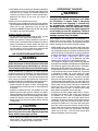
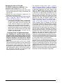
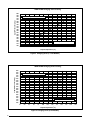
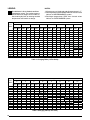
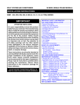
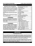
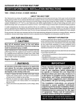
Split system air conditioner
14 SEER, Single Phase Models
Installation Instructions
*S4BE - 018KB, 024KB, 030KB, 036KB (1.5, 2, 2.5, & 3 Ton) Series
IMPORTANT
ATTENTION INSTALLERS:
It is your responsibility to know this product
better than your customer.This includes being
able to install the product according to strict
safety guidelines and instructing the customer
on how to operate and maintain the equipment
for the life of the product. Safety should
always be the deciding factor when installing
this product and using common sense plays
an important role as well. Pay attention to
all safety warnings and any other special
notes highlighted in the manual. Improper
installation of the furnace or failure to follow
safety warnings could result in serious injury,
death, or property damage.
These instructions are primarily intended to
assist qualified individuals experienced in the
proper installation of this appliance. Some
local codes require licensed installation/
service personnel for this type of equipment.
Please read all instructions carefully before
starting the installation. Return these
instructions to the customer’s package for
future reference.
DO NOT DESTROY. PLEASE READ CAREFULLY &
KEEP IN A SAFE PLACE FOR FUTURE REFERENCE.
important SAFETY INFORMATION....................... 2
Air conditioner INSTallATION.......................... 3
General Information.................................................... 3
Before You Install this Unit......................................... 3
Locating the Air Conditioner....................................... 3
Packaging Removal.................................................... 3
Ground Level.............................................................. 3
Roof Mount................................................................. 3
ELECTRICAL WIRING................................................. 4
Pre-Electrical Checklist.............................................. 4
Line Voltage................................................................ 4
Connecting Refrigerant Tubing Between the
Indoor & Outdoor Unit................................................ 4
Grounding................................................................... 5
Thermostat Connections............................................ 5
START UP & ADJUSTMENTS.................................... 5
Pre-Start Check List................................................... 5
Start-Up Procedures................................................... 5
Air Circulation - Indoor Blower.................................. 5
System Cooling........................................................ 5
System Heating (optional)........................................ 6
Air conditioner MAINTENANCE.......................... 6
Refrigerant Charging....................................... 6
Charging the Unit in AC mode.................................... 7
Charging Charts & Application Notes........................ 7
Figure 2. Charging Chart (1.5 Ton Models).............. 8
Figure 3. Charging Chart (2 Ton Models)................. 8
Figure 4. Charging Chart (2.5 Ton Models).............. 9
Figure 5. Charging Chart (3 Ton Models)................. 9
Table 3. Charging Table (1.5 Ton Units).................... 10
Table 4. Charging Table (2 Ton Units)....................... 10
Table 5. Charging Table (2.5 Ton Units).................... 11
Table 6. Charging Table (3Ton Units)........................ 11
Wiring Diagrams.................................................... 12
Figure 6. W.D. for 1.5, 2, 2.5, & 3 Ton Models........... 12
Figure 7. W.D. for 3 Ton Models................................ 13
INSTALLATION / PERFORMANCE CHECKLIST....... 16
REPLACEMENT PARTS.............................................. 16
important SAFETY INFORMATION
INSTALLER: Please read all instructions before servicing
this equipment. Pay attention to all safety warnings and
any other special notes highlighted in the manual. Safety
markings are used frequently throughout this manual to
designate a degree or level of seriousness and should
not be ignored.
WARNING indicates a potentially hazardous situation
that if not avoided, could result in personal injury or death.
CAUTION indicates a potentially hazardous situation
that if not avoided, may result in minor or moderate injury
or property damage.
WARNING:
Shut off all electrical power to the unit before
performing any maintenance or service on the
system. Failure to comply may result in personal
injury or death.
WARNING:
Unless noted otherwise in these instructions,
only factory authorized parts or accessory
kits may be used with this product. Improper
installation, service, adjustment, or maintenance
may cause explosion, fire, electrical shock or
other hazardous conditions which may result in
personal injury or property damage
WARNING:
S4BE Split System Air Conditioners are shipped
charged with R410A refrigerant and ready
for installation. If repairs make it necessary
for evacuation and charging, it should only
be attempted by qualified trained personnel
thoroughly familiar with this equipment. Under
no circumstances should the owner attempt to
install and/or service this equipment. Failure to
comply with this warning could result in property
damage, personal injury, or death.
CAUTION:
This unit uses refrigerant R-410A. DO NOT use
any other refrigerant in this unit. Use of another
refrigerant will damage the unit.
2
WARNING:
The information listed below must be followed
during the installation, service, and operation
of this unit. Unqualified individuals should
not attempt to interpret these instructions or
install this equipment. Failure to follow safety
recommendations could result in possible
damage to the equipment, serious personal
injury or death.
• The installer must comply with all local codes and
regulations which govern the installation of this type
of equipment. Local codes and regulations take
precedence over any recommendations contained in
these instructions. Consult local building codes and the
National Electrical Code (ANSI CI) for special installation
requirements.
• All electrical wiring must be completed in accordance
with local, state and national codes and regulations
and with the National Electric Code (ANSI/NFPA 70)
or in Canada the Canadian Electric Code Part 1 CSA
C.22.1.
• This equipment contains liquid and gaseous refrigerant
under high pressure. DO NOT USE ANY PORTION OF
THE CHARGE FOR PURGING OR LEAK TESTING.
Installation or servicing should only be performed by
qualified trained personnel thoroughly familiar with this
type equipment.
• Fully annealed, refrigerant grade copper tubing should
be used when installing the system. Refrigerant suction
line tubing should be fully insulated.
• Installation of equipment may require brazing operations.
Installer must comply with safety codes and wear
appropriate safety equipment (safety glasses, work
gloves, fire extinguisher, etc.) when performing brazing
operations.
• Follow all precautions in the literature, on tags, and
on labels provided with the equipment. Read and
thoroughly understand the instructions provided with
the equipment prior to performing the installation and
operational checkout of the equipment.
• Refrigerant and electrical line should be routed through
suitably waterproofed openings to prevent water from
leaking into the structure.
Air conditioner INSTallATION
General Information
The S4BE series air conditioner is designed only for
outdoor rooftop or ground level installations. This unit
has been tested for capacity and efficiency in accordance
with AHRI Standards and will provide many years of safe
and dependable comfort, providing it is properly installed
and maintained. Abuse, improper use, and/or improper
maintenance can shorten the life of the appliance and
create unsafe hazards.
To achieve optimum performance and minimize equipment
failure, it is recommended that periodic maintenance be
performed on this unit. The ability to properly perform
maintenance on this equipment requires certain
mechanical skills and tools.
Before You Install this Unit
√ The cooling load of the area to be conditioned must be
calculated and a system of the proper capacity selected.
It is recommended that the area to be conditioned be
completely insulated and vapor sealed.
√ Check the electrical supply and verify the power supply
is adequate for unit operation. The system must be wired
and provided with circuit protection in accordance with
local building codes. If there is any question concerning
the power supply, contact the local power company.
√ The indoor section (air handler, furnace, etc) should be
installed before routing the refrigerant tubing. Refer to
the indoor unit's installation instructions for installation
details.
√ All units are securely packed at the time of shipment and
upon arrival should be carefully inspected for damage
prior to installing the equipment at the job site. Verify
coil fins are straight. If necessary, comb fins to remove
flattened or bent fins. Claims for damage (apparent or
concealed) should be filed immediately with the carrier.
√ Please consult your dealer for maintenance information
and availability of maintenance contracts. Please read
all instructions before installing the unit.
Locating the Air Conditioner
• Survey the job site to determine the best location for
mounting the outdoor unit.
• Sufficient clearance for unobstructed airflow through the
outdoor coil must be maintained in order to achieve rated
performance. See Figure 1 for minimum clearances to
obstructions.
• Overhead obstructions (Figure 1), poorly ventilated
areas, and areas subject to accumulation of debris
should be avoided.
• Consideration should be given to availability of electric
power, service access, noise, and shade.
Packaging Removal
NOTE: To prevent damage to the tubing connections,
carefully remove the carton and user’s manual from the
equipment. Discard the shipping carton.
Ground Level
Ground level installations must be located according to
local building codes or ordinances and these requirements:
• Clearances must be in accordance with those shown
in Figure 1.
• A suitable mounting pad (Figure 1) must be provided
and separate from the building foundation. The pad
must be level and strong enough to support the weight
of the unit. The slab height must be a minimum of 2” (5
cm) above grade and with adequate drainage.
Roof Mount
• The method of mounting should be designed so that it
does not overload roof structures or transmit noise to
the interior of the structure. The roof must be structurally
capable of handling the weight of the unit.
• Full perimeter support is required under the unit.
Support must be made of weather resistant materials
and installed prior to unit installation.
• The support must be built to raise the unit 6" above the
roof.
6” from Building
or Structure
24" for
Service Access
12" or 18”
See Note
DO NOT
OBSTRUCT
TOP OF UNIT
12" or 18”
See Note
NOTE: Units require full perimeter clearances.
Installer must maintain 18” between two units
or 12” between single unit and structure.
48”
2” Mounting Pad
Figure 1. Clearance Requirements
3
Connecting Refrigerant Tubing Between
the Indoor & Outdoor Unit
CAUTION:
ELECTRICAL WIRING
WARNING:
ELECTRICAL SHOCK OR FIRE HAZARD
When servicing, cover or seal openings to
minimize the exposure of the refrigerant system
to air to prevent accumulation of moisture and
other contaminants.
To avoid risk of electrical shock, personal injury,
or death, disconnect all electrical power to the unit
before performing any maintenance or service. The
unit may have more than one electrical supply.
After outdoor and indoor unit placement has been
determined, route refrigerant tubing between the
equipment in accordance with sound installation practices.
Label all wires prior to disconnection when
servicing the unit. Wiring errors can cause improper
and dangerous operation.
• When connecting refrigerant linesets together, it is
recommended that dry nitrogen be flowing through the
joints during brazing to prevent internal oxidation and
scaling.
• Refrigerant tubing should be routed in a manner that
minimizes the length of tubing and the number of bends
in the tubing. If precise forming of refrigerant lines is
required, a copper tubing bender is recommended.
Avoid sharp bends and contact of the refrigerant lines
with metal surfaces.
• Refrigerant tubing should be supported in a manner
that the tubing will not vibrate or abrade during system
operation.
• Tubing should be kept clean of foreign debris during
installation.
• Every effort should be made by the installer to ensure
that the field installed refrigerant containing components
of the system have been installed in accordance with
these instructions and sound installation practices to
insure reliable system operation and longevity.
• The maximum recommended interconnecting refrigerant
line lengths is 75 ft. and the vertical elevation difference
between the indoor and outdoor sections should not
exceed 20 ft. NOTE: For installations exceeding these
conditions, please refer to the Application Guidelines
for Refrigerant Lines Addendum.
• A filter dryer is provided with the unit and must be
installed in the liquid line of the system. If the installation
replaces a system with a filter dryer already present
in the liquid line, the filter dryer must be replaced with
the one supplied with the unit. The filter dryer must be
installed in strict accordance with the manufacturer’s
installation instructions.
• Optional equipment such as liquid line solenoid valves,
low ambient, etc., should be installed in strict accordance
with the manufacturer’s installation instructions.
4
• All electrical connections must be in compliance with
all applicable local codes and ordinances, and with
the current revision of the National Electric Code
(ANSI/NFPA 70).
• For Canadian installations the electrical connections
and grounding shall comply with the current Canadian
Electrical Code (CSA C22.1 and/or local codes).
Pre-Electrical Checklist
√Verify that the voltage, frequency, and phase of the
supply source match the specifications on the unit rating
plate.
√ Verify that the service provided by the utility is sufficient
to handle the additional load imposed by this equipment.
Refer to the unit wiring label for proper voltage wiring.
√ Verify factory wiring is in accordance with the unit wiring
diagram. See Figure 6, (page 12) and Figure 7, (page
13). Inspect for loose connections.
Line Voltage
• A wiring diagram is located on the inside cover of the
electrical box of the outdoor unit. The installer should
become familiar with the wiring diagram before making
any electrical connections to the outdoor unit.
• An electrical disconnect must be located within sight
of and readily accessible to the unit. This switch shall
be capable of electrically de-energizing the outdoor unit.
• Line voltage to the unit should be supplied from a
dedicated branch circuit containing the correct fuse
or circuit breaker for the unit. Incoming field wiring
and minimum size of electrical conductors and circuit
protection must be in compliance with information listed
on the outdoor unit data label. Any other wiring methods
must be acceptable to authority having jurisdiction.
• The outdoor unit requires both power and control circuit
electrical connections. Refer to the wiring diagram /
schematic for identification and location of outdoor
unit field wiring interfaces. See Figure 6. and Figure 7.
Make all electrical connections in accordance with all
applicable codes and ordinances.
• Overcurrent protection must be provided at the branch
circuit distribution panel and sized as shown on the unit
rating label and according to applicable local codes.
See the unit rating plate for minimum circuit ampacity
and maximum overcurrent protection limits.
• Provide power supply for the unit in accordance with the
unit wiring diagram, and the unit rating plate. Connect
the line-voltage leads to the terminals on the contactor
inside the control compartment.
• Use only copper wire for the line voltage power supply
to this unit as listed in Table 1. Use proper code agency
listed conduit and a conduit connector for connecting
the supply wires to the unit. Use of rain tight conduit is
recommended.
• 208/230 Volt units are shipped from the factory wired
for 230 volt operation. For 208V operation, remove the
lead from the transformer terminal marked 240V and
connect it to the terminal marked 208V.
• Optional equipment requiring connection to the power
or control circuits must be wired in strict accordance of
the NEC (ANSI/NFPA 70), applicable local codes, and
the instructions provided with the equipment.
Grounding
WARNING:
The unit cabinet must have an uninterrupted or
unbroken electrical ground to minimize personal
injury if an electrical fault should occur. Do not
use gas piping as an electrical ground!
This unit must be electrically grounded in accordance
with local codes or, in the absence of local codes, with
the National Electrical Code (ANSI/NFPA 70) or the CSA
C22.1 Electrical Code. Use the grounding lug provided in
the control box for grounding the unit.
COPPER WIRE SIZE — AWG
(1% Voltage Drop)
Supply Wire Length-Feet
200
150
100
50
6
4
4
4
3
3
2
2
2
1
8
6
6
4
4
4
3
3
3
2
10
8
8
6
6
6
4
4
4
3
14
12
10
10
8
8
6
6
6
4
Supply Circuit
Ampacity
15
20
25
30
35
40
45
50
55
60
Wire Size based on N.E.C. for 60° type copper conductors.
Table 1. Copper Wire Size
Thermostat
Wire Gauge
Maximum Recommended
Thermostat Wire Length (FT)
24
25
22
45
20
70
18
110
Table 2. Thermostat Wire Gauge
Thermostat Connections
• Thermostat connections should be made in accordance
with the instructions supplied with the thermostat and
the indoor equipment.
• The outdoor unit is designed to operate from a 24 VAC
Class II control circuit. The control circuit wiring must
comply with the current provisions of the NEC (ANSI/
NFPA 70) and with applicable local codes having
jurisdiction.
• The low voltage wires must be properly connected to
the units low voltage terminal block. Recommended
wire gauge and wire lengths for typical thermostat
connections are listed in Table 2.
• The thermostat should be mounted about 5 feet above
the floor on an inside wall. DO NOT install the thermostat
on an outside wall or any other location where its
operation may be adversely affected by radiant heat from
fireplaces, sunlight, or lighting fixtures, and convective
heat from warm air registers or electrical appliances.
Refer to the thermostat manufacturer’s instruction sheet
for detailed mounting and installation information.
START UP & ADJUSTMENTS
Pre-Start Check List
√Verify the indoor unit is level and allows proper
condensate drainage.
√Verify the outdoor coil and top of the unit are free from
obstructions and debris, and all equipment access/
control panels are in place.
√Verify air filters are cleaned and properly installed.
√Verify duct work is sealed to prevent air leakage.
√ Verify line voltage power leads are securely connected
and the unit is properly grounded.
√ Verify low voltage wires are securely connected to the
correct leads on the low voltage terminal strip.
√ Verify power supply branch circuit overcurrent protection
is sized properly.
√Verify the thermostat is wired correctly.
Start-Up Procedures
The thermostat's function mode should be set to OFF and
the fan mode should be set to AUTO. Close all electrical
disconnects to energize the system.
Air Circulation - Indoor Blower
1.Set the thermostat system mode on OFF and the fan
mode to ON.
2.Verify the blower runs continuously. Check the air delivery
at the supply registers and adjust register openings for
balanced air distribution. If insufficient air is detected,
examine ductwork for leaks or obstructions.
3.Set the thermostat fan mode to AUTO and verify the
blower stops running.
System Cooling
1.Set the thermostat’s system mode to COOL and the
fan mode to AUTO. Gradually lower the thermostat
temperature setpoint below room temperature and
verify the outdoor unit and indoor blower energize.
5
2.Verify blower wheel is spinning in direction indicated by
arrow. Feel the air being circulated by the indoor blower
and verify that it is cooler than ambient temperature.
Listen for any unusual noises. If unusual sounds occur,
determine the source of the noise and correct as
necessary.
3.Verify HI and LO refrigerant pressures.
4.Allow the system to operate for several minutes and then
set the temperature selector above room temperature.
Verify the fan and compressor cycle off with the
thermostat. NOTE: The blower should also stop unless
fan mode is set to the ON position.
System Heating (optional)
1.Set the thermostat's system mode to HEAT and the
temperature mode above room temperature.
2.Verify the optional heating equipment (furnace or
electric heat) and indoor blower energize. Feel the air
being circulated by the indoor blower and verify that
it is warmer than ambient temperature. Listen for any
unusual noises. If unusual sounds occur, determine the
source of the noise and correct as necessary.
Air conditioner MAINTENANCE
WARNING:
To prevent electrical shock, personal injury, or
death, disconnect all electrical power to the unit
before performing any maintenance or service.
The unit may have more than one electrical supply.
Proper maintenance is important to achieve optimum
performance from the air conditioner. The ability to properly
perform maintenance on this equipment requires certain
mechanical skills and tools. If you do not possess these
skills, contact your dealer for maintenance. Consult your
local dealer about the availability of maintenance contracts.
Routine maintenance should include the following:
• Inspect and clean or replace air filters at the beginning
of each heating and cooling season, or more frequently
if required.
• Inspect the condensate drain and outdoor coil at the
beginning of each cooling season. Remove any debris.
Clean the outdoor coil and louvers as necessary using a
mild detergent and water. Rinse thoroughly with water.
• Inspect the electrical connections for tightness at the
beginning of each heating and cooling season. Service
as necessary.
CAUTION:
The unit should never be operated without a
filter in the return air system. Replace disposable
filters with the same type and size.
• Do not attempt to add additional oil to motors unequipped
with oil tubes. The compressor is hermetically sealed
at the factory and does not require lubrication.
6
Refrigerant Charging
WARNING:
S4BE Split System Air Conditioners are shipped
charged with R410A refrigerant and ready
for installation. If repairs make it necessary
for evacuation and charging, it should only
be attempted by qualified trained personnel
thoroughly familiar with this equipment. Under
no circumstances should the owner attempt to
install and/or service this equipment. Failure to
comply with this warning could result in property
damage, personal injury, or death.
After refrigerant line connections are completed, it is
required that you leak check and evacuate the indoor
section and all line connections (using proper methods)
before finalizing the full system refrigerant charge.
• S4BE outdoor units with non-AHRI listed indoor coils
are not recommended. Deviations from rated airflows or
non-listed combinations may require modification to the
expansion device and refrigerant charging procedures
for proper and efficient system operation. Refer to Table
3, (page 10), Table 4, (page 10), Table 5, (page
11), or Table 6, (page 11) to determine the ideal
amount of sub-cooling for a given liquid pressure.
• The refrigerant charge can be checked and adjusted
through the service ports provided external to the outdoor
unit. Use only gage line sets which have a “Schrader”
depression device present to actuate the valve.
• A high-pressure switch is factory-installed and located
in the liquid line internal to the outdoor unit. The switch
is designed to protect the system when very high
pressures occur during abnormal conditions. Under
normal conditions, the switch is closed. If the liquid
pressure rises above 575 psig, then the switch will open
and de-energize the outdoor unit. The switch will close
again once the liquid pressure decreases to 460 psig.
Please note that the switch interrupts the thermostat
inputs to the unit. Thus, when the switch opens and
then closes, there may be a 5 minute short cycling
delay before the outdoor unit will energize.
• A low-pressure switch (select models only) is factoryinstalled and located in the suction line internal to
the outdoor unit. The switch is designed to protect
the compressor from a loss of charge. Under normal
conditions, the switch is closed. If the suction pressure
falls below 5 psig, then the switch will open and deenergize the outdoor unit. The switch will close again
once the suction pressure increases above 20 psig.
Please note that the switch interrupts the thermostat
inputs to the unit. When the switch opens and then
closes, there will be a 5 minute short cycling delay
before the outdoor unit will energize.
Charging the Unit in AC mode
(At outdoor temperatures above 55° F for
optimized sub-cooling of 10° F - 12° F.)
1.With the system operating at steady-state, measure the
liquid refrigerant pressure (in psig) at the outdoor unit
service valve.
2.Measure the liquid refrigerant temperature (in
Fahrenheit) at the service valve.
3.Determine the required liquid refrigerant pressure from
Table 3, (page 10), Table 4, (page 10), Table 5,
(page 11), or Table 6, (page 11).
• If the pressure measured in Step 1 is greater than
the required liquid refrigerant pressure determined
in Step 3, then there is too much charge in the
system. Remove refrigerant and repeat Steps 1
through 3 until the system is correctly charged.
• If the pressure measured in Step 1 is less than the
required liquid refrigerant pressure determined in
Step 3, there is too little charge in the system. Add
refrigerant and repeat Steps 1 through 3 until the
system is correctly charged.
Charging Charts & Application Notes
• This equipment’s cooling system contains
refrigerant under high pressure. Always use safe
and environmentally sound methods when handling
refrigerant handling or servicing the unit. Review
the factory literature and safety warnings prior to
servicing.
• When repairing system leaks, always use a nitrogen
(inert) gas to protect the refrigerant system and pressure
check the repair before re-charging. Always replace
the filter-dryers when performing any repair to the
refrigeration system with one capable of acid removal.
After completing the repairs, evacuate the system to
350 - 500 microns and weigh in the refrigerant to the
amount specified on the unit rating label.
• The refrigerant charging charts Figure 2, (page 8),
Figure 3, (page 8), Figure 4, (page 9), & Figure 5,
(page 9) are applicable only to matched assemblies
of NORDYNE equipment and listed airflows for the
indoor coil. NOTE: Before using these charts, make
sure the unit is in a stable operating mode. As shown
in the charts, the ideal system sub-cooling can vary
over the range of operation. Reference the charts to
determine the ideal amount of sub-cooling for a given
liquid pressure. Units charged to other values will not
perform at the rated unit efficiency (EER) or rated
Coefficient of Performance (COP) in heating mode.
• Table 3, (page 10), Table 4, (page 10), Table 5,
(page 11), or Table 6, (page 11) are valid for a
variety of indoor, return air conditions and are most
influenced by the outdoor ambient temperature, outdoor
fan operation and the unit operating voltage. Before
using these tables, make sure the unit is in a stable
operating mode. The ideal system sub-cooling can vary
over the range of operation. Reference the tables to
determine the ideal amount of sub-cooling for a given
liquid pressure. Units charged to other values will not
perform at the rated unit efficiency (EER) or rated
Coefficient of Performance (COP) in heating mode.
• To inspect a systems operation using quality instruments,
match the measured liquid temperature to the units table.
The measured liquid pressure reading should be within
3% of the table value for most installations.
• For systems that are operating with more than a 5%
deviation, inspect the unit for the proper voltage and
phase balance and the refrigeration system for leaks.
• Units that are operating at less then 95% of the nominal
voltage or with a 2% phase imbalance may see a more
significant deviation than the amount stated above.
• DO NOT use the charts in systems that have a fan cycling
under low-ambient control. Refer to the low-ambient kit
instructions for more information (If applicable).
7
Liquid Pressure (psig)
S4BE-018KB Charging Chart -Cooling
600
580
560
540
520
500
480
460
440
420
400
380
360
340
320
300
280
260
240
220
200
Remove refrigerant when above curve
Add refrigerant when below curve
75
80
85
90
95
100
105
110
115
120
125
130
135
Liquid Temperature ( F)
0
Figure 2. Charging Chart (1.5 Ton Models)
Liquid Pressure (psig)
S4BE-024KB Charging Chart -Cooling
600
580
560
540
520
500
480
460
440
420
400
380
360
340
320
300
280
260
240
220
200
Remove refrigerant when above curve
Add refrigerant when below curve
75
80
85
90
95
100
105
110
115
Liquid Temperature (0 F)
Figure 3. Charging Chart (2 Ton Models)
8
120
125
130
135
Liquid Pressure (psig)
S4BE-030KB Charging Chart -Cooling
600
580
560
540
520
500
480
460
440
420
400
380
360
340
320
300
280
260
240
220
200
Remove refrigerant when above curve
Add refrigerant when below curve
75
80
85
90
95
100
105
110
115
120
125
130
135
Liquid Temperature (0 F)
Figure 4. Charging Chart (2.5 Ton Models)
Liquid Pressure (psig)
S4BE-036KB Charging Chart -Cooling
600
580
560
540
520
500
480
460
440
420
400
380
360
340
320
300
280
260
240
220
200
Remove refrigerant when above curve
Add refrigerant when below curve
75
80
85
90
95
100
105
110
115
120
125
130
135
Liquid Temperature (0 F)
Figure 5. Charging Chart (3 Ton Models)
9
Legend
NOTES:
1.All pressures are listed psig and all temperatures in °F
2.Discharge temperatures greater than charted values
indicate an undercharged system.
3.Discharge temperatures less than charted values
indicate an overcharged system.
Shaded boxes indicate flooded conditions.
Rated design values. The suction pressure
will be lower than design value if indoor air
flow, entering dry bulb, or entering wet bulb
temperatures are lower than design.
OUTDOOR TEMPERATURE (°F)
Suct.
Press.
70
75
80
85
90
95
100
105
Liq.
Dis.
Liq.
Dis.
Liq.
Dis.
Liq.
Dis.
Liq.
Dis.
Liq.
Dis.
Liq.
Dis.
Liq.
Dis.
Press. Temp. Press. Temp. Press. Temp. Press. Temp. Press. Temp. Press. Temp. Press. Temp. Press. Temp.
141
242
111
143
241
116
264
115
145
241
121
264
120
286
119
147
242
124
263
125
286
123
308
122
149
243
128
264
127
286
128
308
127
330
265
131
287
130
308
131
330
130
352
287
133
309
134
331
134
353
133
374
155
310
136
331
137
353
137
375
137
396
138
157
311
139
332
139
354
140
376
140
397
140
333
142
355
143
376
143
398
143
355
145
377
146
399
146
378
148
399
149
400
151
151
153
159
126
161
130
163
134
165
167
Table 3. Charging Table (1.5 Ton Units)
OUTDOOR TEMPERATURE (°F)
Suct.
Press.
132
134
136
138
140
142
144
146
148
150
152
154
156
158
70
75
80
85
90
95
105
Liq.
Dis.
Liq.
Dis.
Liq.
Dis.
Liq.
Dis.
Liq.
Dis.
Liq.
Dis.
Liq.
Dis.
Liq.
Dis.
Press. Temp. Press. Temp. Press. Temp. Press. Temp. Press. Temp. Press. Temp. Press. Temp. Press. Temp.
255
257
259
258
259
127
129
131
137
140
277
279
280
280
281
130
132
135
139
143
299
301
302
303
304
133
136
139
142
146
322
323
324
325
326
327
136
139
142
146
149
152
344
345
346
347
348
349
138
142
146
149
152
155
367
367
368
369
370
371
Table 4. Charging Table (2 Ton Units)
10
100
141
145
149
152
155
158
389
390
390
391
392
394
144
148
152
155
158
161
412
412
412
413
414
416
146
151
155
159
161
164
Legend
NOTES:
1.All pressures are listed psig and all temperatures in °F
2.Discharge temperatures greater than charted values
indicate an undercharged system.
3.Discharge temperatures less than charted values
indicate an overcharged system.
Shaded boxes indicate flooded conditions.
Rated design values. The suction pressure
will be lower than design value if indoor air
flow, entering dry bulb, or entering wet bulb
temperatures are lower than design.
OUTDOOR TEMPERATURE (°F)
Suct.
Press.
125
127
129
131
133
135
137
139
141
143
145
147
149
151
70
75
80
85
90
95
100
105
Liq.
Dis.
Liq.
Dis.
Liq.
Dis.
Liq.
Dis.
Liq.
Dis.
Liq.
Dis.
Liq.
Dis.
Liq.
Dis.
Press. Temp. Press. Temp. Press. Temp. Press. Temp. Press. Temp. Press. Temp. Press. Temp. Press. Temp.
241
242
243
244
245
123
128
132
137
142
263
264
265
266
267
128
132
136
140
145
286
286
287
288
289
133
137
140
144
148
308
308
309
310
310
311
137
141
144
147
151
154
330
330
331
332
332
333
142
145
148
151
154
157
352
352
353
354
354
355
146
149
152
155
158
161
374
374
375
375
376
376
150
153
155
158
161
164
396
396
397
397
398
398
154
156
159
162
165
167
Table 5. Charging Table (2.5 Ton Units)
OUTDOOR TEMPERATURE (°F)
Suct.
Press.
134
136
138
140
142
144
146
148
150
152
154
156
158
160
70
75
80
85
90
95
100
105
Liq.
Dis.
Liq.
Dis.
Liq.
Dis.
Liq.
Dis.
Liq.
Dis.
Liq.
Dis.
Liq.
Dis.
Liq.
Dis.
Press. Temp. Press. Temp. Press. Temp. Press. Temp. Press. Temp. Press. Temp. Press. Temp. Press. Temp.
243
244
245
246
246
117
121
125
128
133
266
267
267
268
269
122
126
129
133
137
288
289
290
290
291
126
130
134
137
141
311
311
312
313
314
314
131
134
138
141
145
149
333
334
334
335
336
337
135
139
142
146
149
153
355
356
357
358
358
359
140
143
146
150
153
157
378
378
379
380
381
381
144
147
150
154
157
160
400
401
402
402
403
404
148
151
154
158
161
164
Table 6. Charging Table (3Ton Units)
11
Wiring Diagrams
WIRING DIAGRAM
Split System Air Conditioner (Outdoor Section)
Single Phase
NOTES:
1. Disconnect all power before servicing.
1. Couper le courant avant de faire letretien.
2. For supply connections use copper conductors only.
2. Employez uniquement des conducteurs
to “H” on
3. Not suitable on systems that exceed 150 volts to ground.
en cuivre.
capacitor
4. For replacement wires use conductors suitable for 105 deg C.
3. Ne convient pas aux installations
RED
5. For ampacities and overcurrent protection, see unit rating plate.
.
de plus de 150 volt a la terre.
6. Connect to 24 vac/40ca/class 2 circuit. See furnace/airhandler installation
to T2 on BLACK
2
instructions for control circuit and optional relay/transformer kits.
capacitor
R
3
7. Anti-Shor t Cycle Timer (ASCT) may or may not be installed in the unit. If desired,
START
ASCT is factory installed on select models only or may be field installed as shown using
BLACK
1
RELAY
C
manufacturer’s approved kit. If not present, connect Yellow and Black wires per Note 6.
8. DO NOT use a Hard Start Kit on a model with a PTCR installed .
S
YELLOW
OUTDOOR
START
FAN
MOTOR
208/230V
BLUE
CAPAC
L2
L1
F
ORANGE
PTCR
CCH
to”C” on
COMPRESSOR
C
BLACK
(OPTIONAL)
YELLOW
capacitor
CONTACTS
DUAL
BLACK
CAPACITOR
T2
T1
H
R
PTCR(If equipped)
YELLOW/
BLACK
C
S
H
COMPRESSOR
C
F
S
R
BLACK
CONTACTOR
ASCT
(SEE NOTE 7)
C OUTDOOR FAN
MOTOR
BLACK
YELLOW
R
T1
T3
C
YELLOW
BLACK
S
RED
HPS
CC - Contac tor Coil
CCH - Crankcase Heater
HPS - High Pressure Switch
WIRE NUT
LEGEND:
FIELD WIRING
LOW VOLTAGE
HIGH VOLTAGE
SEE NOTE 6
CRANKCASE
HEATER
(OPTIONAL)
Figure 6. W.D. for 1.5, 2, & 2.5 Ton Models
12
L2
HPS
ASCT
24 VOLT FIELD
CONNECTIONS
T2
T2
ASCT
(SEE NOTE 7)
CC
T1
L1
GROUNDING
SCREW
L1 L2 GND
7110050
WIRING DIAGRAM
Split System Air Conditioner (Outdoor Section)
Single Phase
NOTES:
1. Disconnect all power before servicing.
2. For supply connections use copper conductors only.
3. Not suitable on systems that exceed 150 volts to ground.
4. For replacement wires use conductors suitable for 105 deg C.
5. For ampacities and overcurrent protection, see unit rating plate.
6. Connect to 24 vac/40ca/class 2 circuit. See furnace/airhandler installation
instructions for control circuit and optional relay/transformer kits.
7. Anti-Short Cycle Timer (ASCT) may or may not be installed in the unit.
C
installed as shown using manufacturer’s approved kit. If not present, connect
Yellow and Black wires per Note 6.
8. DO NOT use a Hard Start Kit on a model with a PTCR installed.
ORANGE
S
BLUE
208/230V
COMPRESSOR
CONTACTS
T1
YELLOW
R
PTCR(If equipped)
YELLOW
PTCR
T2
YELLOW/
BLACK
C
S
H
ASCT
(SEE
NOTE 7)
COMPRESSOR
C
F
S
R
YELLOW
START
CAPAC
to”C” on
capacitor
YELLOW
T1
L1
BLACK
CONTACTOR
T1
T3
HPS
T2
L2
BLACK
BLACK
YELLOW
R
C
YELLOW
BLACK
S
ASCT
CC - Contactor Coil
CCH - Crankcase Heater
HPS - High Pressure Switch
1
BLACK
BLACK
CC
24 VOLT FIELD
CONNECTIONS
START
RELAY
T2
C OUTDOOR FAN
MOTOR
ASCT
(SEE NOTE 7)
H
2
3
DUAL
CAPACITOR
C
CCH
(OPTIONAL)
BLACK
OUTDOOR
FAN MOTOR
F
L2
L1
to “H” on
capacitor
RED
1. Couper le courant avant de faire letretien.
2. Employez uniquement des conducteurs
en cuivre.
3. Ne convient pas aux installations
to T2 on
de plus de 150 volt a la terre.
capacitor
R
RED
WIRE NUT
HPS
LEGEND:
SEE NOTE 6
CRANKCASE
HEATER
(OPTIONAL)
FIELD WIRING
LOW VOLTAGE
HIGH VOLTAGE
L1
GROUNDING
SCREW
L2 GND
7114520
8/14
Figure 7. W.D. for 3 Ton Models
13
14
15
INSTALLATION / PERFORMANCE CHECKLIST
ELECTRICAL SYSTEM
INSTALLATION ADDRESS:
CITY_________________________
STATE_________________
Electrical connections tight?
YES
NO
Line voltage polarity correct?
YES
NO
UNIT MODEL #_________________________________________
Rated Voltage:____________________________________ VOLTS
UNIT SERIAL #________________________________________
L1-L2 Volts:______________________________________ VOLTS
INSTALLER NAME:
L1-L3 Volts:______________________________________ VOLTS
CITY________________________
STATE_________________
Unit Installed Minimum clearances
shown on page 3?
YES
NO
Has the owner’s information been
reviewed with the customer?
YES
NO
Has the Literature Package been left
with the unit?
YES
NO
YES
Avg. Volts:_______________________________________ VOLTS
Max. deviation of voltage
from avg. volts:____________________________________ VOLTS
% Volt imbalance:_________________________________ VOLTS
REFRIGERATION SYSTEM
Was unit given 24 hr warm up period
for crankcase heaters?
L2-L3 Volts:______________________________________ VOLTS
NO
Blower Motor HP:_________ Sheave Setting____________# Turns
Has the thermostat been calibrated?
YES
NO
Stage-1 Liquid Pressure (high side)_________________________
Is the thermostat level?
YES
NO
Stage-1 Suction Pressure (low side)_________________________
Is the heat anticipator setting correct?
(If Applicable)
YES
NO
PROPOSITION 65 WARNING:
REPLACEMENT PARTS
WARNING:This product contains chemicals known
to the state of California to cause cancer.
Replacement parts are available through all Nordyne
distributors. Please have the complete model and serial
number of the unit when ordering replacement parts.
WARNING:This product contains chemicals known
to the state of California to cause birth defects or
other reproductive harm.
Specifications & illustrations subject to change
without notice or incurring obligations (09/14).
Electrical:
• Capacitors
• Compressors
• Contactors
• Pressure Switches
• Relays
Motors:
• Blower Motor
• Fan Motor
Components:
• Blower Assembly
• Cabinet Panels
• Expansion Valves
•
•
•
•
Temperature Limit Switches
Thermostats
Time Delay Relays
Transformers
• Fan Grille
• Filter/Driers
7096660 (NEW)