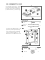
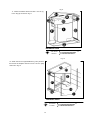
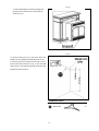
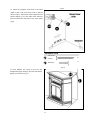
1
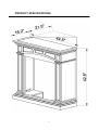
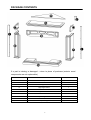
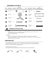
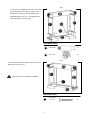
CORNER COMBO
WOOD FIREPLACE MANTEL
Model #FBD400TCC-M-HC/MO
FBD400RTCC-M-HC/MO
Questions about installation, Operation or troubleshooting?
Before returning to your retailer, contact our customer service department at 1-877-886-5989,
8:00a.m.—4:30p.m., EST, Monday—Friday or e-mail [email protected].
PC-FBD400-M3-1101
PRODUCT SPECIFICATIONS
2
PACKAGE CONTENTS
If a part is missing or damaged - return to place of purchase (exterior wood
components are not replaceable).
PART
DESCRIPTION
QUANTITY
A
Top
1
B
Panel
1
C
Left Upper Panel
1
D
Right Upper Panel
1
E
Left Lower Panel
1
F
Right Lower Panel
1
G
Base
2
H
Top Triangle Panel
1
I
Backboard
2
J
Set Square Support
3
HARDWARE CONTENTS
Part
Description
AA
Cam Dowel
Quantity
Picture
(Shown to size) 16
Part
FF
Description
ST4 Screw
5/8 in.
Quantity
Picture
(Shown to size)
18
BB
Cam Lock
CC
Wall Anchor
16
GG
BB
2
Connector
Bracket HH
White Key
3
1
ST4 Screw
DD
1 -3/16 in.
ST5 Screw
EE
2- 3/8 in.
ST4 Screw
II
8
1 -9/16 in.
8
JJ
2
M6 Screw
1 -3/8 in.
4
WARNINGS AND CAUTIONS
WARNING y
When tightening screws, do not over tighten, this may cause threads to strip. We recommend using a
hand-held screwdriver rather than a power screwdriver.
y
Do not force screws into holes. CAUTION y
For corner installations(optional); if baseboards are installed where the fireplace is intended to be
displayed, then the fireplace will not fit flush against the wall. For a proper flush fit, you may need to remove
part of the baseboard mold if necessary.
PREPARATION
Before beginning assembly of product, make sure all hardware contents parts are present. Compare parts with
package contents list and diagram on page 4. If any part is missing or damaged, do not attempt to assemble the
product. Contact customer service for replacement parts.
Estimated Assembly Time: 60 minutes
Tools Required for Assembly: Philips Screwdriver, Flathead Screwdriver, Drill, and Tape Measure.
4
ASSEMBLY INSTRUCTIONS
Fig 1
1. Fasten the Left Upper Panel (C) and the Left
Lower Panel (E) with M6 Screw 1-3/8 in. (JJ) as
shown in Fig 1. Do the same thing for the Right
Upper Panel (D) and the Right Lower Panel (F).
Hardware Used
JJ
M6 Screw
×4
1 -3/8 in.
Fig 2
2. After assembling the mantel (C, D, E, F), insert Cam
Locks (BB) into Panel (B), screw in Cam Dowels (AA)
into the Left Upper Panel (C) and the Right Upper Panel
(D). Attach Panel (B) into assembled frame (C, D, E, F)
by tightening the Cam Locks (BB) as shown in Fig 2.
Hardware Used
AA
Cam Dowel
×4
BB
Cam Lock
×4
BB
5
Fig 3
3. Insert Cam Locks (BB) into the Left Lower Panel
(E) and the Right Lower Panel (F), screw in Cam
Dowels (AA) into Base (G). Attach Base (G) into
assembled frame (B, C, D, E, F) by tightening the
Cam Locks (BB) as shown in Fig 3.
Hardware Used
AA
Cam Dowel
×6
BB
Cam Lock
×6
Fig 4
4. Fasten the batten with ST4Screw 1-9/16 in. (II) to the
Base (E) as shown in Fig 4.
Skip to step 9 for Corner Mantel Installation.
Hardware Used
II
6
ST4 Screw
1 -9/16 in.
×4
Fig 5
5. Insert Cam Locks (BB) into Panel (B), the Left Upper
Panel (C) and the Right Upper Panel (D), screw in Cam
Dowels (AA) into Top (A). Attach Top (A) into
assembled frame (B, C, D, E, F) by tightening the Cam
Locks (BB) as shown in Fig 5.
Hardware Used
AA
Cam Dowel
×6
BB
Cam Lock
×6
Fig 6
6. Fasten the batten with ST4 Screw 1-9/16 in. (II) to
the Top (A) as shown in Fig 6.
Hardware Used
II
7
ST4 Screw
1 -9/16 in.
×4
Fig 7
7. After assembling the mantel, lift upright and push
the insert from the front of the mantel as shown in
Fig 7.
Fig 8
8. Position the fireplace to the desired place as
shown in Fig 8.
8
FOR CORNER APPLICATION
Fig 9
9. Turn the fireplace Top (A) Panel over. Using the
Connector Brackets (GG) that supplied, connect
the Fireplace Top (A) to the Top Triangle Panel
(H) with ST4 Screw 5/8 in. (FF) as shown in Fig 9.
Hardware Used
FF
GG
ST4 Screw
×18
5/8 in.
Connector
Bracket
×3
Fig 10
10. Insert Cam Locks (BB) into Panel (B), the Left
Upper Panel (C) and the Right Upper Panel (D),
screw in Cam Dowels (AA) into Top (A). Attach
Top (A) into assembled frame (B, C, D, E, F) by
tightening the Cam Locks (BB) as shown in Fig 10.
Hardware Used
AA
Cam Dowel
×6
BB
Cam Lock
9
×6
Fig 11
11. Fasten the batten with ST4 Screw 1-9/16 in. (II)
to the Top (A) as shown in Fig 11.
Hardware Used
AA
II
ST4 Screw
×4
1 -9/16 in.
BB
Fig 12
12. Attach the left and right Backboard (I) trim pieces to
the back of the fireplace with ST4 Screw 1-3/16 in. (DD)
as shown in Fig 12.
Hardware Used
DD
ST4 Screw
1 -3/16 in.
10
×8
Fig 13
13. After assembling the mantel, lift upright and
push the insert from the front of the mantel as
shown in Fig 13.
Fig 14
14. Drill two holes (5/16 in) in the corner where the
fireplace is to be displayed. Drill the first hole 44-1/2
in. from the ground up, and the second hole 1-9/16 in.
from the first hole as shown in Fig 14. Put the Wall
Anchor (CC) in the holes by pinching the anchor tabs
together as shown in Fig 14.
Hardware Used
CC
11
Wall Anchor
×2
Fig 15
15. Attach the triangular wood block to the holes
drilled in step 8 with ST5 Screw 2-3/8 in. (EE) as
shown in Fig 15. This block is used to support the Set
Square Support (J). For thin walls, insert white key
(HH) into wall anchor and push to “pop” open anchor
wings.
Hardware Used
EE
ST5 Screw
×2
2 3/8 in.
HH
×1
White Key
Fig 16
16. Push fireplace into corner so that the Top
Triangle Panel (H) is resting on top of the Set Square
Support (J) as shown in Fig 16.
12
REPLACEMENT PARTS LIST
Part
Description
Part #
Quantity
Hardware Package
HP007
1
AA
Cam Dowel
PCAM-023
16
BB
Cam Lock
PCAM-023
16
CC
Wall Anchor
ML066-01
2
DD
ST4 Screw 1-3/16 in.
GB/T 951 4×30
8
EE
ST5 Screw 2-3/8 in.
GB/T 950 5×60
2
FF
ST4 Screw 5/8 in.
GB/T 951 4×16
18
GG
Connector Bracket
SJ002
3
HH
White Key
ML067-01
1
II
ST4 Screw 1-9/16 in.
GB/T 951 4×40
8
JJ
M6 Screw 1-3/8 in.
GB/T 818 6×35
4
13
WARRANTY INFORMATION
Keep This Warranty
IMPORTANT: We urge you to fill your warranty registration card within TEN(10) days of date of
installation, complete with the entire serial number which can be found on the rating plate. Retain this
portion of the card for your record.
Always specify model and serial numbers when communicating with customer service.
We reserve the right to amend these specifications at any time without notice. The only warranty
applicable is our standard written warranty. We make no other warranty, expressed or implied.
LIMITED WARRANTY:
PRO-COM warrants this product to be free from defects in materials and components for TWO (2) years
from the date of first purchase, provided that the product has been properly installed, operated and
maintained in accordance with all applicable instructions, to make a claim under this warranty, the Bill of
Sale or cancelled check must be presented.
RESPONSIBILITY OF OWNER
This warranty is extended only to the original retail purchaser. This warranty covers the cost of part(s)
required to restore this heater to proper operating condition and an allowance for labor when provided by
a PRO-COM Authorized Service Center.
Warranty part(s) MUST be obtained through authorized dealers of this product and/or PRO-COM who will
provide original factory replacement parts. Failure to use original factory replacement parts voids this
warranty. The heater MUST be installed by a qualified installer in accordance with all local codes and
instructions furnished with the unit.
WHAT IS NOT COVERED
This warranty does not apply to parts that are not in original condition because of normal wear and tear or
parts that fail or become damaged as a result of misuse, accidents, lack of proper maintenance or defects
caused by improper installation. Travel, diagnostic cost, labor, transportation and any and all such other
costs related to repairing a defective heater will be the responsibility of the owner.
TO THE FULL EXTENT ALLOWED BY THE LAW OF THE JURISDICTION THAT GOVERNS THE SALE
OF THE PRODUCT, THIS EXPRESS WARRANTY EXCLUDES ANY AND ALL OTHER EXPRESSED
WARRANTIES AND LIMITS THE DURATION OF ANY AND ALL IMPLIED WARRANTIES. INCLUDING
WARRANTIES OF MERCHANTABILITY AND FITNESS FOR A PARTICULAR PURPOSE TO TWO (2)
YEARS ON ALL COMPONENTS FROM THE DATE OF FIRST PURCHASE. PRO-COM'S LIABILITY IS
HEREBY LIMITED TO THE PURCHASE PRICE OF THE PRODUCT AND PRO-COM SHALL NOT BE
LIABLE FOR ANY OTHER DAMAGES WHATSOEVER INCLUDING INDIRECT. INCIDENTAL OR
CONSEQUENTIAL DAMAGES.
Some states do not allow a limitation on how long an implied warranty lasts or an exclusion or limitation of
accidental or consequential damages, the above limitation on implied warranties, or exclusion or
limitation on damages may not apply to you.
This warranty gives you specific legal right, and you may also have other rights that vary from state to
state
.
Print in China
14