1
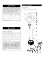
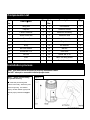
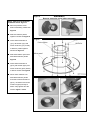
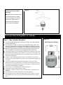
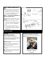
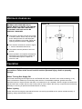
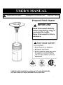
USER'S MANUAL READ BEFORE USE! Factory No.: HYPH50061-48 Style No.: 66694 Propane Patio Heater IMPORTANT Read this manual carefully before assembling, using or servicing this heater. Keep this manual for future reference. COMPLIES WITH ANSI Z83.26a-2008/CSA 2.37a-2008 STANDARDS FOR GAS-FIRED OUTDOOR INFRARED PATIO HEATERS 1 Contents General Safety Information...................................... .2 Assembly Instructions Components……………............................................ 4 Components List………............................................ 5 Installation Process Step1 - Attach Post Assembly to Cylinder Housing...5 Step 2 –Attach Head Assembly to Post.....................6 Step 3 –Attach Reflector Stud to Head Assembly…. 6 Step 4 –Attach Center Reflector to Reflector Panel...7 Step 5 –Attach Reflector Assembly to the top of Head Assembly…………………… 8 Connect Hose & Regulator to Cylinder……………… 8 Check for leaks......................................................... 9 Minimum clearances................................................ 10 Operation…………................................................... 10 Storage ………..........................................................12 Service...................................................................... 14 Do not store or use gasoline or other flammable vapor and liquids in the vicinity of this or any other appliance. General Safety Information An LP-cylinder not connected for use shall not be stored in the vicinity of this or any other appliance. Maintenance............................................................. 12 propane fueled equipment. 2 3 24 4 Components List Part No. Description Qty Part No. Description Qty 1 Wing Nut 3 2 Flat Washer 9 3 Cap Nut 9 4 Reflector Panel 3 5 Center Reflector 1 6 Reflector Assembly 1 7 Small Screw M6 9 8 Reflector Stud 3 9 Heater Burner Screen 1 10 Head Assembly 1 11 Post 1 12 Regulator 1 13 Body 1 14 Ф6 washer 3 15 Ф6 lock washer 3 16 M6 Nut 4 17 Screw M4 X 12 2 18 Door fixer 1 19 M6 Nut 1 20 Screw M6 X 30 1 21 Door 1 22 M8 X 30 Wing screw 1 23 Feet 4 24 Small flat washer 9 Installation process Note: You must follow all steps to properly assemble heater. Do NOT attempt to assemble without proper tools. Step 1 – Attach Post Assembly to Cylinder Housing Figure 1 ■ Insert the post through the bottom of the body. Attach the post to the body using Ф6 washer (3pcs), Ф6 lock washer (3pcs) and M6 nut (3pcs). Please see Figure 1. 5 Step 2 –Attach Head Assembly to Post Figure 2 ■ Unscrew pre-assembled bolts (4pcs) form head assembly. Please see Figure 2. ■ Load head assembly by inserting gas hose into post. Please see Figure 3. Figure 3 ■ Insert head assembly into post. Attach using bolts (4pcs). Tighten securely. Please see Figure 4. Figure 4 Figure 5 Step 3 –Attach Reflector Studs to Head Assembly ■ Attach reflector studs (3pcs) and flat washers (3pcs) to the top of head assembly and tighten the securely. Please see Figure 5. . 6 Figure 6 WARNING! Remove protective cover before assemble. Step 4 –Attach Center Reflector to Reflector Panel. Figure 9 ■ Remove protective cover before assembling. Please see Figure 6 ■ Slide two reflector panels together. Please see Figure 8 ■ Insert small screw M6*10 Figure 7 (1pc), Ф6 washer (1pc) and screw on M6 nut (1pc) loosely to attach 2 panels together. Please see Figure 8. ■ Slide third reflector panel onto assembled reflector panels. Figure 8 ■ Insert small screw M6*10 (2pcs), Ф6 washer (2pcs) and screw on M6 nut (2pcs) loosely to attach. Please see Figure 8 ■ Place center reflector over assembled reflector panels Figure 8 and insert small screw M6*10 (6pcs) , Ф6 washer and screw on M6 nut (6pcs) loosely to attach. Fully tighten all of the screws. Figure 7 and 8. 7 Step 5 –Attach Reflector Assembly to the top of Head Assembly Figure 9 ■ Attach reflector assembly to the top of head assembly by sliding reflector assembly over reflector studs (3pcs). Fasten with flat washers (6pcs) and wing nuts (3pcs). Please see Figure 9. Connect Hose & Regulator to Cylinder Step 1 – Gas Cylinder Required You must provide propane gas and propane cylinder. Use a standard 20lb. propane cylinder only. ■ Use this heater only with a propane vapor withdrawal supply system. See Chapter 5 of the Standard for Storage and Handling of Liquefied Petroleum Gas, ANSI/NFPA 58.Your local library or fire department will have this book. ■ Maximum supply pressure of 250 psi. A minimum supply pressure of 11.0 W.C. is required for the purpose of input adjustment for propane gas. ■ ■ The pressure regulator and hose assembly supplied with the appliance must be used. ■ The installation must conform with local codes, or in the absence of local codes, with Figure 10 20LB Propane Cylinder National Fuel Gas Code, ANSI Z223.1/ NFPA 54, Natural & Propane installation code, CSA B149.1 as applicable. ■ A dented, rusted or damaged propane cylinder may be hazardous and should be checked by your cylinder supplier. Never use a propane cylinder with a damaged valve connection. ■ The propane cylinder must be constructed and marked in accordance with the specifications for LP gas cylinders of the U.S. Department of transportation (DOT) or the Standard for Cylinders Spheres &Tubes for transportation of Dangerous Goods & Commission, CAN/CSA-B339, as applicable. ■ Never connect an unregulated propane cylinder to the heater. ■ Provided with a listed overfilling prevention device. ■ Provided with a cylinder connection device compatible with the connection for the appliance. ■ Do not store a share LP-Gas cylinder under or near this appliance. ■ Place the dust cap on the cylinder valve outlet when ever the cylinder is not in use. Only install the type of dust cap on the cylinder valve is provided with the cylinder valve. 8 Step 2 – Install Cylinder on the base. Figure 11 ■ Put the gas cylinder in the metal stand. Make sure the gas tank sits on the metal stand completely. Turn the wing screw on the outer part of metal stand clockwise to secure the gas tank tightly. Please see Figure 11 Step 3 –Connect the Regulator to the gas cylinder valve. CAUTION: Always confirm that the burner control knob is in the “OFF” position before connecting the gas supply. Insert the nipple of the regulator into the Figure 12 cylinder valve and tighten the black coupling nut by turning it clockwise. Hand tighten only. Once the regulator is connected to the cylinder valve, be sure that all connections are tightened before lighting the patio heater. See Figure 12 Check for leaks Warning: Perform Leak test outdoors only. Never leak test when smoking. Do not use a flame to check for leaks. NOTE: Whenever gas connections are loosened or removed, you must perform a complete leak test. Figure 15 Your Patio Heater has been checked at all factory connections for leaks. To check the connection of the regulator/cylinder: See Figure 15 ■ Make leak solution by mixing 1 part liquid dish soap and 3 parts water. ■ Brush several drops (or use spray bottle) of the solution onto the gas hose/regulator and regulator/cylinder connection. ■ Turn on gas. Inspect the connections and look for bubbles. ■ If no bubbles appear, the connection is safe. ■ If bubbles appear, there is a leak, loosen and re-tighten this connection. 9 Minimum clearances BE CAREFUL: WHEN CERTAIN MATERIALS OR ITEMS ARE Stored, ABOVE, BESIDE OR UNDER THIS HEATER WHILE IN USE, THEY WILL BE SUBJECT TO RADIANT HEAT AND COULD BE SERIOUSLY DAMAGED. Figure 16 ■ This heater is primarily used for the heating of outdoor patios, decks, and pool and spa areas. Always make sure that adequate fresh air ventilation is provided. Follow the spacing tolerances shown in Figure 16. ■ The minimum clearances, shown in Figure 1, must be maintained at all times. ■ This heater must be placed on firm level ground. ■ Never operate in an explosive atmosphere. Keep away from areas where gasoline or other flammable liquids or vapors are stored or used. Operation WARNING: DO NOT attempt to operate heater until you have read and understand all precautions. Failure to do so can result in serious personal injury, death or property damage. Before Turning Gas Supply ON Your heater was designed and approved for OUTDOOR USE ONLY. DO NOT use it inside a building, or any other enclosed area. Make sure surrounding areas are free of combustible materials, gasoline and other flammable vapors or liquids. Ensure that there is no obstruction to air ventilation. Be sure all gas connections are tight and there are no leaks. Be sure the access panel is clear of debris. Be sure any component removed during assembly or servicing is replaced and fastened prior to starting. Before Lighting Heater should be thoroughly inspected before each use and by a qualified service person at least annually. If relighting, always wait at least 5 minutes. 10 Lighting Figure 17-1 Figure 17-2 Note: This heater is equipped with a Pilot Light that allows for safer startups and shutdowns. Pilot must be lit before Main Burner can be started. ■ Open valve at gas cylinder. ■ Open Viewing Hole by sliding cover to either side. (See Figure 18) ■ Push Control Knob IN and rotate to Pilot position. (See Figure 17-1) Note: For initial start or after any cylinder change, hold Control Knob IN for 2 minutes to purge air from gas lines before proceeding. ■ While depressing control knob, press spark igniter button to light up Pilot. And be visible through Viewing Hole. ■ Release Control Knob after 30-60 seconds. Pilot Light will remain lit. If not, return to step 1. ■ Turn Control Knob to LO or HI position. (See Figure 17-2) Main Burner will light immediately. Flame is visible through Viewing Hole. If not, return to step 1. Figure 18 Viewing Hole Figure 19 Match lighter WARNING: If spark igniter fails to light the pilot after 30 seconds, release control knob, turn to “OFF” position (See Figure 20) , all valves should be closed and wait 5 minutes before relight. ■ If for some reason your spark igniter fails to deliver a spark, your heater can be started by inserting a lit match through the viewing hole (See Figure 19) while pushing the control knob in while in the “PILOT” position(See Figure 17-1). Observe the flame pattern When heater is ON: ■ When lit for the first time the heater may emit a slight odor and smoke. This is a normal temporary condition caused by the “burn in” of paints and lubricants used in the manufacturing process and will not occur again. Simply run the heater on “high” for 30 minutes. ■ Emitter screen will become bright red due to intense heat. The color is more visible at night. Burner will display tongues of blue flame. These flames should not be yellow or produce thick black smoke, indicating an obstruction of airflow through the burners. Never leave the heater unattended while in use. 11 Shut down Figure 20 ■ Turn Control Knob clockwise to Pilot. (Normally, burner will make a slight popping sound when extinguished.) Burner will extinguish but Pilot will remain ON. ■ To extinguish Pilot, depress Control Knob and continue to turn it clockwise to OFF. (See Figure 20). ■ Turn off gas supply at the valve of gas cylinder. ■ Disconnect the cylinder and remove when the heater is not in use. Storage Note: Wait until heater is cool before covering. When heater is not in use for a prolonged period of time, remove gas cylinder. Verify that the gas cylinder valve is closed tightly. Do not store the gas cylinder indoors, store gas cylinder in a well ventilated area. Maintenance To obtain the best performance from your heater make sure you perform the following maintenance activities on a regular basis: ■ Keep exterior surfaces clean. Use warm soapy water for cleaning. Never use flammable or corrosive cleaning agents. Be sure to keep the area around the burner and control assembly dry at all times. ■ Keeping the ventilation openings of the cylinder enclosure free and clear from debris. Visually checking burner flames with pictorial representations shown on page 11. ■ Airflow must be unobstructed. Clear insect nests or webs away from your heater’s exterior and interior using a straight piece of wire and wire brush or vacuum cleaner at least once a year or immediately upon indication of any of the following systems: a. Flashback b. Smell the fuel gas c. Predominate yellow flames d. Excessive popping noises during operation e. Uneven emitter glow Carbon deposits may create a fire hazard. Clean dome and emitter with warm soapy Water if necessary. Caution: Never use wood or plastic, it may break and block the parts. Never spray any cleaning product on the emitter grid or burner area. 12 Troubleshooting and replacement parts To learn how to service and procure parts for worn out, defective or damaged components which shown in below list need replace please contact your selling dealer or call us directly for assistance. Please provide us with heater’s model number and the serial number. Warning: Use our original equipment replaced parts only. Use unauthorized parts or modification of parts can void warranty and create an unsafe condition. PROBLEM Pilot will not light PROBABLE CAUSE Gas valve may be OFF Turn the gas valve ON Gas Cylinder empty Refill LP gas cylinder Orifice blocked Debris around pilot Clean or replace orifice Purge air from lines, with knob in pilot position, depress and hold in, to release air. Check all fittings Use match to light pilot; obtain new igniter and replace Clean dirty area Thermocouple bad Replace thermocouple Gas leak in line Check connections Pressure is low Refill or replace LP gas cylinder Orifice blocked Remove, clean and replace Thermocouple is bad Replace thermocouple Pilot light assembly bent or not in correct location Place pilot in proper position and retry Gas pressure is low Turn cylinder valve OFF and replace cylinder Air in supply system Loose connection Igniter is not sparking Pilot will not stay on Burner won’t light Burner flame is low SOLUTION Outdoor temperature is less than 40ºF and tank is less than 1/4 full Supply hose is bent or kinked Use a full cylinder Straighten hose Carbon build up Dirt or film on reflector and burner screen Clean reflector and burner screen Thick black smoke Blockage in burner Remove blockage and clean burner inside and outside 13 Service ■ A hazardous condition may result if a heater is used that has been modified or is not functioning properly. When the heater is working properly: • The flame is contained within the heater. • The flame is essentially blue. • There is no strong disagreeable odor, eye burning or other physical discomfort. • There is no smoke or soot internal or external to the heater. • There is no unplanned or unexplained shutdown of the heater. • There is no Flashback. • There are no excessive popping noises during operation. • There is no diminished and uneven emitter glow. The parts list shows the heater as it was constructed. Do not use a heater, which is different from that shown. In this regard, only the cylinder connections and regulator supplied with the heater. Do not use alternative parts. For this heater the regulator is set for 11.0” water column outlet pressure. If there is any uncertainty about the regulator setting, have it checked. A heater that is not working properly must be repaired, but only by a trained, experienced service person. ■ If your heater needs maintenance or is not working properly, please contact your local authorized agent for service. It is a necessity to contact an authorized source for replacement of parts and/or other servicing. IF YOU HAVE QUESTIONS OR CONCERNS PLEASE CALL BOND TOLL FREE # 1-866-771-BOND (2663) OR TO BETTER EXPEDITE YOUR REQUEST FEEL FREE TO EMAIL US [email protected] OR LOG IN TO OUR WEBSITE UNDER CUSTOMER SERVICE SUPPORT www.bondmfg.com BOND MANUFACTURING CO. 1700 West 4th Street Antioch, CA 94509 USA 14