1
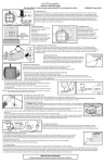
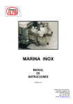
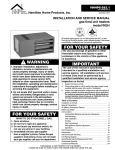
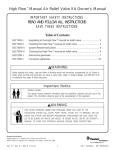
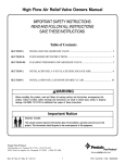
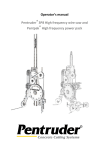
PLEASE READ TEMPLATE FIRST
Pad retainer
Electric valve
(HSA 215)
Water diffuser (HPC 004)
This line
must be level
4''+
12 HF Humidifier
Electronically controlled FLOW-THRU model
This humidifier MUST be connected to a drain.
REPLACEMENT PART NUMBERS IN BRACKETS
VERSION 8- December 2014
1 Assembling the unit
This unit is reversible, and can be mounted on either the hot air or return air ducts. Find the best location and determine how the humidifier
will be installed. Select the top. Install and fasten the water diffuser, the long black plastic piece, with two screws #6 x 1/2" inside the top of the
humidifier. Install the electric valve (mounted on a plastic bracket) outside of the top of the humidifier. While supporting the water diffuser with
one hand, insert the plastic tube protruding from the valve into the hole in the middle of the top part of the humidifier making sure that the
plastic tubing is firmly seated in the hole of the water diffuser. Fasten the valve assembly to the unit with 4 screws # 6 x 1/2" (Kit #10). Finally,
install the plastic pad retainer by snapping it in the hole located in the middle of the humidifier frame.
Warning : Always check that you are not about to cut or drill into any air conditioning or electrical accessory during installation.
2 Cutting the opening
The humidifier is recommended to be installed on the cold air return,
but may be mounted to the warm air plenum as well. On whichever
duct you decide to install the humidifier, draw a level line for
placement of the template. If installing on the warm air duct, make
sure the line is at least 4 inches above the furnace housing for
clearance of the drain tube.
Attach the template to the duct. Punch and drill the four corners for
the opening and the four fastening holes with a 3/32” drill. Remove
the template and complete the opening outline with a marker. Cut
the opening in the plenum. Beware of sharp edges in the duct.
3 Installing the unit
Install the unit in the opening. Use the
four screws (#8 x 3/4") to attach the
humidifier body to the duct. The ribs
around the humidifier back opening
must fit into the rectangular opening in
the duct. Check that the humidifier
body is level from side to side. Then
fasten the unit completely.
4 Installing the collar and the flex duct (HSA 130)
Install the 6" duct collar in a convenient location on the opposite duct with four screws (#8 x 3/8"). Using the gear clamp provided, fit the
flexible duct onto the collar and tighten gear clamp. Slide the damper assembly into the side opening of the humidifier until it snaps.
Make sure to position the damper knob in front of the unit. Measure the required flex duct length to the duct collar so it does not sag. Cut
the excess portion. Slide the flexible duct on the air take-off collar and secure it using the second gear clamp.
5 Installing the drain tube (HPC 133)
Select a convenient drain location for running the drain tube. Before you connect the tube to the drain
fitting, slip the hose clamp over the tube. Push the drain tube (1/2" I.D.) over the drain fitting located at
the bottom of the unit and secure it in place with the hose clamp. Make sure the tube has no bends
and the water can flow easily in a straight manner to the drain without accumulating in the tube.
6 Installing the evaporator pad (EP 037)
The pad is enclosed in a plastic frame having molded markings that clearly indicates the bottom. Slide the pad into the bottom
part of the humidifier, the little bump at the top facing to you, then push the pad against the back opening of the humidifier. Lock the pad in place with the pad
retainer.
7 Installing the water supply valve (HSA 140) on a copper pipe
A plastic bag contains a brass valve and all the material required to install the water supply valve. Water is
taken from the nearest cold water pipe suitable for the supply valve installation. Do not install this on a
plastic pipe. Shut off the main water valve.
Nylon
Note : Please make sure that the piercing pin is completely recessed into the valve body by turning the handle counter clockwise.
Do not use the saddle valve to adjust water flow. It is designed to be fully open or closed.
•
•
•
•
Brass
Assemble one side of the top clamp to the bottom clamp with a screw and a nut.
Make sure that the rubber gasket is in place over the piercing needle and position the valve assembly on the copper water line.
Assemble the other side of the top clamp to the bottom clamp with the remaining screw and nut.
Tighten the two screws so that the valve is firmly attached to the water pipe. The two sides of the clamp must be parallel.
8 Connecting the water supply tubing (HSA 170) to the water hammer absorber and the valve (HSA 215)
• This water hammer absorber is connected to the electric valve in factory.
• Install the water supply tubing on the side of the water hammer absorber that has a compression
fitting to receive the supply tubing.
• Slip the brass compression nut onto the plastic supply tube, then the nylon sleeve with its most
tapered end towards the end of the tube. Finally, install a brass insert into the end of the
plastic tubing.
• Push the supply tube fully into the brass compression fitting. Tighten the brass compression nut
with small wrenches, without stripping the threads, using the double wrench method in order to
apply the torque on the fitting only.
• Then do the same operation at the other end of the supply tube and make the connection to the saddle valve previously installed on the copper supply pipe.
• Turn the valve handle completely clockwise until it stops. This will pierce the copper pipe and close the valve.
• This saddle valve is designed to be fully open or closed. Do not use it to adjust the water flow.
Copper
Plastic
NOTE : The brass sleeve supplied with the brass valve Kit #10 is to be used only if the plastic tubing is replaced by copper tubing (not recommended).
9 Installing the electronic controller (HSA 055)
• The HSA055 is factory set at NO TEMP, with settings for HIGH TEMP and LOW TEMP. The NO TEMP setting is used when the humidifier is supplied
power from the furnace. The unit will run as long as there is power AND the humidistat is calling for more humidity.
• The LOW TEMP setting is used for furnaces that generate less heat, such as those with a heat pump. The unit may operate for a short while after the
furnace has stopped due to residual heat in the duct.
• The HIGH TEMP setting is used for furnaces that generate more heat, typically oil or gas furnaces. You may have to try both settings to see which one is
right for you.
• To choose the setting on the controller, set the dip-switches, as shown on the controller. For HIGH and LOW settings, the controller must be installed on the warm air
duct with two screws (#8 x ½”). There are two lights on the controller: the green LED means there is power to the controller and the blue LED cycles on as the valve opens.
When switched ON by the humidistat, the controller opens the electric valve for approximately 2 seconds and then closes the valve for another 30, and so on. Please use
Template #3 and drill the 3 holes.
Electronic Controller
(HSA 055)
Transformer
(HEC025)
HSA 055
VALVE
Valve (HSA 215)
24VAC
DIP
Switches
Humidistat
(DS00284
Electronic Controller
10 Wiring between the humidistat (DS00284), the transformer (HEC025)
and the electronic controller (HSA 055)
1- Push the two quick connectors on the humidistat terminals identified COM and NO.
2- Split the wire coming from the transformer in two, long enough to connect one end to the humidistat
(terminal COM) and the other one to the electronic controller (terminal 24VAC).
3- Use the separate piece of single wire to connect the other terminal 24VAC of the controller to the terminal NO.
4- Use the double wire to connect the valve to the two terminals (terminal VALVE) in the centre of the controller.
NOTE : The quick connectors at the end of the double wire are not the same size.
The small ones go to the controller and the bigger ones to the electric valve.
11 Installing the humidistat (DS00284) and the transformer (HEC025)
This humidifier is supplied with a transformer that can be plugged in to any 120V electric outlet. The humidistat is a duct mounted type.
It is better to mount the humidistat on the RETURN duct because it will detect the air being returned to the furnace without being disturbed by a sudden
increase in moisture (as from a kitchen or bathroom). This will offer better humidity control.
Kit No. 4 contains all the material you need to install the humidistat.
• The humidistat should be installed on a flat and vertical surface of the RETURN duct a minimum of 6 inches above the humidifier.
• Attach the humidistat template (#2) on the duct.
Warning : Always check that you are not about to cut or drill into any air conditioning or electrical accessory during installation.
• Mark and drill the mounting holes and cut an opening for the humidistat.
• Run the control wires through an opening located at the bottom of the front panel of the humidistat.
• Hold the wires while you install the humidistat in the opening. Check that the metal of the duct neither touches the connections nor cuts the wire insulation. Then fasten the humidistat
to the duct. The humidistat mechanism is exposed in the duct. Temporarily install the control knob on the humidistat.
12 Humidifier Start-up.
Open the saddle valve, put the furnace power back on and start the furnace in a heating cycle. Set the humidistat at the maximum setting.
After a few ON/OFF cycles of the electric valve, you should see water flowing through the drain tube. Check that the water is evenly distributed by the water diffuser across the pad. Carefully check
that both ends of the water supply tube are firmly held in place by their respective compression fitting. Set the humidistat according to the recommended setting on the label. Check the system
several times to make sure there is a free flow in the drain tube and there is no leak before leaving the installation unattended. When everything is working fine, affix the adhesive nameplate on the
humidifier cover.
12 HF Humidifier
Owner's Instructions for Electronically controlled FLOW-THRU Humidifier
Operating and Maintenance Tips - Warranty.
3. A few tips
•
Do not use the supply valve (installed on the supply line) to regulate the water flow. This type of valve is
designed to be completely opened or closed.
•
Do not allow the drain tube to fill with water in bends, elbows or kinks. Water could accumulate inside the
drain tube leading to deposit build-up and/or result in back pressure preventing the water from draining
properly and cause an overflow.
1. Principle of operation
•
This humidifier uses a vertical evaporator pad, wetted by a pulsed water flow. Warm air is by-passed from
the warm air plenum and forced through the evaporator pad. Humid air is drawn back into the return duct.
•
The pad is enclosed in a plastic frame with a marking that clearly indicates the bottom. It is designed to
retain water before it is evaporated. Any excess water is sent to the drain.
•
All flow-through humidifiers improve performance and evaporative capacities if they are used
with constant blower operation. However, this unique pulse action model optimizes performance and
reduces water consumption by up to 80%.
•
When the humidity level drops below the set point on the humidistat and the furnace is running, the patented
electronic controller activates the unit. Small amounts of fresh water are then added intermittently (approximately
2 seconds on and 30 seconds off) during the heat cycle and dispersed onto the media pad. The humidified air is
then circulated throughout your entire home. This is one of the main features of this model and it saves up to 80%
of water consumption compared to other flow through humidifiers which continually dispense water onto the
evaporator pad. It is normal to have some water flowing in the drain tube. This flushing–away method removes
the dissolved minerals left on the evaporator pad and carried away to a floor drain before they settle and dry-up on
the pad.
2. Adjusting the humidity level in your home
•
A relative humidity environment of 40% is recommended. Please refer to the table on the humidistat front
plate to help determine the proper level.
Outside
Temperature
- 22°F
- 13°F
- 4°F
+ 5°F
+ 14°F
above 23°F
•
•
(-30ºC)
(-25ºC)
(-20ºC)
(-15ºC)
(-10ºC)
(-5ºC)
Recommended
Setting
15 %
20 %
25 %
30 %
35 %
40 %
At the beginning of the heating season it might take some time (a few days) to build up the humidity to
the comfortable level you want. Depending on the original dryness of the house, carpets, furniture and
wood will absorb moisture before feeling a difference.
If your house remains unoccupied during the winter season, adjust the humidistat to a lower setpoint in
order to prevent condensation.
4. Annual Maintenance
To
1234-
replace the evaporator pad :
Unplug the transformer from the wall power supply.
Open the humidifier by removing the plastic screw on the side of the cover.
Unlock the evaporator pad by turning the little plastic retainer at the top of the pad.
Remove the old pad and replace it by a new one while checking the printed marking that clearly indicates
the bottom of the pad.
5- Lock the new pad in place.
6- Put the cover back and secure it with the plastic screw.
Note : Depending on the quality of water, it is recommended to replace the evaporator pad once per
heating season.
5. Summer season
•
If the system is used in air conditioning during the summer, reduce the air volume going through the
humidifier by closing the air damper located on the side of the humidifier. The control button shows
the actual position of the damper.
• It is recommended to simply shut off the humidifier system :
1- Close the water supply valve.
2- Turn the humidistat knob to the "OFF" position.
3- Unplug the transformer.
6. Warranty
This humidifier is guaranteed against any defects in material and workmanship, under normal use, for
one (1) year from the date of purchase. The frame and door are guaranteed for life against defects in
material and workmanship, under normal use. This warranty applies only if the unit is properly installed
and operated according to the instructions provided with this product. This warranty will not cover defects
due to misuse or faulty installation. The manufacturer will not be held responsible for any bodily injuries or
damages to personal property or real estate, whether caused directly or indirectly by the humidifier.
If warranty service is required during the warranty period, the manufacturer will, at its sole discretion,
repair or replace the product, without charge, upon delivery of the product where it was purchased, with
proof of purchase.
7. Questions
Please contact customer service at:
1-800-879-0123
or
www.HamiltonHomeProducts.com
POR FAVOR LEA PRIMERO LA PLANTILLA
Pestillo del tapón
Válvula
electrónica
(HSA 215)
Difusor de agua (HPC 004)
Nivelar
la línea
Humidificador 12 HF
Modelo a flujo continuo controlado electrónicamente.
Este humidificador SE DEBE conectar a un tubo de desagüe.
NÚMERO DE LAS PIEZAS DE
RECAMBIO ENTRE PARÉNTESIS
VERSION 8 - Diciembre 2014
1 Montaje del aparato.
Este humidificador es reversible y debe escoger cual será la parte superior. Determine la ubicación y como instalar el
humidificador. Atornillar el difusor de agua, la larga pieza negra de plástico, con 2 tornillos #6 x 1/2" al interior de la parte superior
del humidificador. Instalar la válvula eléctrica (montada-instalada sobre el soporte de plástico) al exterior de la parte superior.
Sosteniendo el difusor de agua con una mano, insertar el pequeño tubo de plástico sobresalido de la válvula en el hueco que se
sitúa en el centro de la parte superior de la unidad asegurándose de que el tubo esté bien instalado hasta el fondo del hueco en
el difusor de agua. Atornillar la válvula en el humidificador con 4 tornillos #6 x 1/2" (bolsa #10). Finalmente, instalar el pequeño
pestillo de plástico (reteniendo el tapón) en el hueco que se sitúa en el centro de la caja del humidificador.
Cuidado : Siempre verificar que no perfore o corte accesorios electrónicos o del aire acondicionado.
2 Recorte la abertura para el conducto.
El humidificador se puede montar al aire caliente pleno o el retorno de
aire frío del conducto. Trazar una línea horizontal en el conducto que
recibirá el humidificador. Si lo instalan en un conducto de aire caliente,
asegúrense de trazar una línea a al menos cuatro pulgadas más arriba
del contramarco del horno para así dejar un espacio a la instalación del
tubo de drenaje.
Pegar la plantilla al conducto. Taladrar y perforar cuatro “agujeros de
esquina” de la abertura y cuatro más “agujeros de fijación” con un taladro
de 3/32”. Quitar la plantilla pegada en el conducto, completar el trazado
de la abertura y recortar el conducto. Cuidado con los bordes afilados del
conducto.
4''+
3 Instalación del humidificador.
Instalar el aparato en la abertura.
Atornillar 4 tornillos (#8 x 3/4")
para colocar el humidificador en el
conducto. El armazón al dorso del
humidificador debe encajarse en
la abertura del conducto. Verificar
que la caja del humidificador está
bien nivelado de un lado para el
otro y luego atornillar los tornillos
completamente.
4 Instalación del collarín y conducto flexible (HSA 130).
Instalar el collarín de plástico de 6" en un lugar apropiado sobre el conducto opuesto cortar una abertura y atornillarlo con 4 tornillos (#8 x
1/2"). Colocar el postigo en la abertura del lado del humidificador hasta que se abroche. Asegurarse de que el botón de mando del postigo
esté por adelante. Medir bien el largo del conducto flexible para que no cuelgue y luego cortar el excedente. Colocar el conducto flexible en el
collarín y postigo. Luego, instalar el conducto flexible insertándole 4 clavijas de plástico a través del vinilo entre dos cables de refuerzo.
5 Instalación del tubo de desagüe (HPC 133).
Escoger un lugar práctico para traer el tubo de desagüe en él. Antes de conectar el tubo de desagüe en la boquilla
que se encuentra debajo del humidificador, meter el anillo de cierre en el tubo. Introducir el tubo (1/2" I.D.) en la
boquilla y atarlo con el anillo de cierre. Asegurarse de que el tubo no esté torcido así el agua no se acumule allí y
pueda circular libremente hacia el tubo de desagüe.
6 Instalación del tapón evaporador (EP 037).
El tapón está instalado en un cuadro de plástico con una marca que indica "parte inferior". Introducir el tapón abajo del humidificador
poniendo hacia adelante la pequeña abolladura. Luego, empujar el tapón contra la abertura hacia el fondo del humidificador y
mantenerlo allí con el picaporte de plástico.
7 Instalación de la válvula de alimentación (HSA 140) en un conducto de agua de cobre.
La válvula de latón con todo el material necesario para instalar la conexión de agua se encuentra en una bolsa
de plástico. La conexión de agua se hace sobre un conducto de agua fría cerca del humidificador. La utilización
de ventilación permanente mejora la capacidad de evaporación del aparato.
Latón
Nylon
Nota : Asegurarse de que la aguja de perforación esté bien colocada al interior de la válvula girando completamente la manija hacia la
izquierda. No use la válvula de alimentación para regular el flujo del agua. Está hecho para estar completamente abierto o cerrado.
• Montar uno de los lados de la abrazadera superior con la abrazadera inferior por medio de un tornillo y tuerca de seguridad.
• Asegurarse de que la junta hermética de caucho este en su sitio en la aguja y instalar la válvula en el tubo de agua de cobre.
• Atornillar el segundo lado de la abrazadera superior a la abrazadera inferior con un tornillo y tuerca de seguridad que sobran.
• Ajustar los dos tornillos de tal modo que la válvula este fermamente atada en el tubo de agua. Las dos partes de la abrazadera deben estar en paralelo.
8 Conexión del tubo de alimentación (HSA 170) al amortiguador y válvula (HSA 215).
• El amortiguador está conectado a la válvula electrónica en la fábrica.
• Instalar el tubo de alimentación del otro lado del amortiguador. Este lado está dotado
de un empalme de compresión para recibir el tubo de alimentación.
• Introducir la tuerca de compresión de latón sobre el tubo de alimentación de plástico,
luego el anillo de nylon con la parte más afilada hacia el extremo del tubo. Finalmente,
introducir la contera de latón a la extremidad del tubo de plástico.
• Empujar al fondo el tubo del empalme de compresión. Ajustar la tuerca de compresión
por medio de pequeñas llaves utilizando el método de dos llaves con fin de aplicar
una sola torsión en el empalme.
• Luego, repetir la misma operación en la otra extremidad del tubo de alimentación y conectarlo en la válvula de conexión de agua ya instalada en el tubo grande de cobre.
• Girar completamente la manija de la válvula hacia la derecha y hasta el fondo. Esto perforará el tubo y cerrará la válvula. Esta válvula está
hecha para ser completamente abierta o cerrada. No usarla para controlar el flujo de agua.
Cobre
Plástico
NOTA : El anillo de latón dada con la válvula y bolsa #10 es utilizada solo si el tubo de plástico es remplazado por un tubo de cobre (no recomendado).
9 Instalación del controlador electrónico (HSA 055).
•
El controlador electrónico de modelo HSA 055 es ajustado en fábrica a la posición NO TEMP, con opciones para el HIGH TEMP y LOW TEMP.
NO TEMP es utilizado cuando el humidificador está conectado directamente al horno. El humidificador funcionará en cuanto reciba electricidad Y el
humidistato pida humedad.
•
LOW TEMP es utilizado para un horno de baja temperatura, como por ejemplo una termobomba. Puede ser que el humidificador continue
funcionando después del paro del horno debido a la acumulación de calor en el conducto.
•
HIGH TEMP es utilizado para un horno de alta temperatura, como los de gas o con aceite.
•
Para elegir la posición en el controlador electrónico, colocar el puente sobre las clavijas de los terminales correspondientes, como indicado sobre el
controlador. Para las opciones HIGH y LOW, se debe instalar el controlador en un conducto de aire caliente por medio de dos tornillos (# 8 x 1/2”). Hay
dos indicadores luminosos sobre el controlador: el verde indica que hay corriente y el azul se alumbra cuando la válvula está abierta. Cuando el
controlador está activado por el humidistato, la válvula electrónica se abre por unos dos segundos luego se cierra por unos treinta segundos, así
sucesivamente. Utilizar la plantilla # 3 y perforar tres orificios.
conducto electrónico
(HSA 055)
HSA 055
VALVE
24VAC
transformador
(HEC025)
puente de
las clavijas
humidistato
(DS00284)
valvula (HSA 215)
10 Conexión del controlador , del humidistato y tranformador
1- Empujar los dos conectadores rápidos en los terminales del humidistato identificadas por COM y NO.
2- Separar en dos el cable proveniente del transformador, tomar una distancia suficiente para conectar
una parte a los cables del controlador electrónico (24VAC) y la otra parte al del humidistato
identificado por el COM.
3- Utilizar un pedazo de cable dado separamente para conectar un extremo al controlador electrónico (24VAC)
y el otro al humidistato identificado por el NO.
4- Utilizar el cable para conectarlo a la válvula en los terminales identificados como "VALVE" al centro del controlador.
NOTA : Los conectadores rápidos de cada extremo son de diferentes tamaños.
Los pequeños van al controlador y los grandes a la válvula eléctrica.
11 Instalación del humidistato (DS00284) y transformador (HEC025).
Este humidificador viene con un transformador donde se puede instalar en cualquiera tomacorriente de 120V. El humidistato es un modelo
montado en un conducto. El montaje en el conducto de RETORNO permite un mejor control de la humedad general en la casa sin estar
influenciado por la humedad súbita (cocina, baño), pues asegura un mejor control de la humedad.
La bolsa #4B contiene todo el material necesario para instalar el humidistato.
•
El humidistato se debe instalar en una pared vertical del conducto de RETORNO de 6" mínimo más arriba encima del humidificador.
•
Pegar la plantilla del humidistato (#2) en el conducto.
Cuidado : Siempre verificar que no perfore o corte accesorios electrónicos o del aire acondicionado.
•
•
•
controlador electrónico
Plantilla
30
20
10
40
50
60
Marca y perforar los orificios de montaje y recortar la abertura para el humidistato.
Introducir los cables en una pequeña entalladura situada abajo de la caja del humidistato.
Manteniendo los cables en las entalladuras mientras instale el humidistato en la abertura y luego atornillarlo en el conducto con 4 tornillos. Verificar que el conducto de metal
no toque los conectadores y que no corte el aislante de los cables. El mecanismo está expuesto al interior del conducto. Instalar provisionalmente el botón de control del humidistato.
12 Poner en marcha el humidificador.
Abrir la válvula de alimentación, restablecer la corriente para el horno y ponerla en marcha en un ciclo de calentamiento. Girar el botón del humidistato al máximo. Después de
algunos ciclos ON/OFF de la válvula electrónica, correrá un poco de agua por el tubo de desagüe. Verificar que el agua este distribuida de manera igual en el tapón de evaporación.
Examinar minuciosamente que las dos extremidades del tubo de alimentación de agua estén firmemente mantenidos en su lugar en los empalmes de compresión. Después de
haberle quitado el paper protector, pegarle la etiqueta en la parte de adelante del humidistato y reinstalar el botón. Ajustar el humidistato siguiendo las normas recomendadas en la
etiqueta. Poner en marcha el sistema varias veces para asegurarse de que el agua no circule libremente en el tubo de desagüe y que no se derrame antes de dejar el humidistato
sin vigilancia. Una vez terminada la instalación y el aparato funcionando correctamente, pegarle la etiqueta en la tapa del humidificador.
Humidificador 12 HF
Instrucciones para el poseedor del humidificador a "flujo continuo" controlado electrónicamente.
Consignas de funcionamiento y mantenimiento - Garantía.
3. Algunas recomendaciones
•
No use la válvula de alimentación (instalada en el tubo de agua) para ajustar el flujo de agua. Esta
válvula esta hecha para estar completamente abierta o cerrada.
•
No deje que el agua se estanque en las curvas o codos de tubos de desagüe porque estos lugares son
propicios a acumulaciones de pozos calcáreos. Además, podría suceder un bloqueo en el tubo
impidiendo el flujo natural del agua y causando un desbordamiento.
1. Principio de funcionamiento
•
Este humidificador utiliza un tapón evaporador vertical que se moja por flujo continuo de agua. El aire
desviado en el conducto de aire caliente es echado a través del tapón por donde se carga de humedad
evaporando el agua. El aire húmedo es aspirado en el conducto de orígen.
•
El tapón evaporador está instalado en un cuadro de plástico en donde la parte inferior está bien
identificada. El tapón está hecho para retener el agua antes de que se evapore. El excedente de agua es
expulsado en el tubo de desagüe.
•
Todos los humidificadores que funcionan a flujo continuo aumentan su capacidad de evaporación cuando
son utilizados con una ventilación permanente. Si comparamos este modelo de humidificador a otros
aparatos, este modelo exclusivo a flujo continuo optimiza el rendimiento y reduce el consumo de agua
hasta un 80%.
•
Cuando el horno produce calor y que el humidistato necesita humedad, el módulo electrónico permite un
flujo controlado de agua en el tapón evaporador. Abre la válvula electrónica por unos 2 segundos y luego
lo cierra en unos 30 segundos y así sucesivamente, dando el agua empapado en el tapón tiempo para
evaporarse en el sistema sin gastar mucha agua que normalmente sería expulsado en el desagüe. Una
de las grandes ventajas de este modelo es la reducción de consumo de agua hasta un 80%. Sin
embargo, es posible ver un poco de agua que se derrame en el tubo de desagüe. Este método de
limpieza retira los minerales que todavía están presentes en el tapón en su proceso de evaporación
antes de que se depositen y endurezcan. Este método con poco consumo de agua puede considerarse
simplemente como un ciclo de “enjuague y evacuación”.
2. Cómo ajustar el nivel de humedad en su casa
•
Un nivel de humedad de 40% es recomendable. Tenga a bien de referirse al tablero sobre la etiqueta del
humidistato para determinar el nivel apropriado.
Temperatura
Exterior
-22°F
-13°F
-4°F
+4°F
+14°F
más de 23°F
•
•
(-30°C)
(-25°C)
(-20°C)
(-15°C)
(-10°C)
(-5°C)
Nivel
recomendado
15%
20%
25%
30%
35%
40%
Al principio del invierno, el grado de humedad deseado en la casa podría demorarse unos días antes de
que se regularise. La absorción de humedad se hara según el grado de sequía, las alfombras, los
muebles y los entablados van absorber la humedad antes de observar un buen cambio.
Si la casa está desocupada durante la sesión invernal, ajustar el humidistato a menor grado a fin de
evitar todo tipo de condensación.
4. Mantenimiento anual
123456-
Para remplazar el tapón evaporador:
Desconectar el transformador del tomacorriente
Abrir el humidificador quitándole el tornillo de plástico del lado de la tapa.
Quitarle el cerrojo del tapón girando sobre su eje el pestillo de plástico arriba del tapón.
Quitarle el tapón viejo y reemplazarlo por uno nuevo teniendo en cuenta las marcas que indican la parte
de abajo.
Echarle el cerrojo al tapón colocado.
Meter de nuevo la tapa y atornillarla con los tornillos de plástico.
Nota : Dependiendo de la calidad de agua, se recomienda cambiar el tapón evaporador una vez al año.
5. Sesión estival
•
Si se usa el sistema (humidificador) en aire acondicionador durante el verano, reducir el flujo de aire que
pasa a través el humidificador cerrando el postigo colocado del lado del aparato. El botón le enseña la
verdadera posición del postigo.
•
123-
La simple interrupción del sistema humidificador se recomienda:
Cerrar la válvula de alimentación.
Girar el botón del humidistato a 'OFF'.
Desconectar el transformador.
6. Garantía
Este humidificador tiene garantía por un año a partir de la fecha de compra contra todos los defectos de
materiales y mano de obra. La caja y tapa están garantizado de por vida contra todos los defectos de
materiales y mano de obra. Esta garantía solo se aplicara si este producto está instalado y utilizado como
se debe siguiendo las instrucciones dadas con el aparato y no cubrirá los defectos debido a un empleo
abusivo o una mala instalación.
De ningún modo, el fabricante se hara responsable de prejuicio a la persona o propriedad causados
directamente o indirectamente por esta instalación. Si este aparato se revela defectuoso durante el
período de garantía (un año) el fabricante se compromete, a su propia merced, en repararlo o
reemplazarlo gratuitamente, devolviendo al lugar donde lo adquirio con una prueba de compra.
7. ¿Preguntas?
Tener a mano este número de teléfono si necesita asistencia.
1-800-879-0123
ó
www.HamiltonHomeProducts.com
23/32"
(18.2 mm)
Humidifier 12 HF
The 12 HF model can be installed on either the supply or return plenum
of a forced air heating system. It is easily reversible for right or left hand.
The total dimensions are: 15" x 15" x 9".
The opening in the duct is 9-1/4" x 8-1/4".
In selecting the best location for the unit, please take both dimensions
and serviceability in consideration.
If the furnace is equipped with a central cooling system, the damper
of the unit should be closed during the cooling season.
for electronic controller
TEMPLATE # 3
8-1/4" (210 mm)
1-5/32"
(29.4 mm)
This line must be level
24VAC
Humidistat
(DS00284
Transformer
(HEC025)
Drill 8 holes - Drill 3/32"
DIP
Switches
23/32"
(18.2 mm)
9-11/16" (246 mm)
CUT HERE
Electronically Controlled
Pulsed Flow Humidifier
Please read the instructions carefully
before starting the installation.
Humidistat Template Included
with Humidistat package
BOTTOM
6-15/16" (176 mm)
Valve (HSA 215)
VALVE
HSA 055
Electronic Controller
(HSA 055)
1- Please beware of sharp edges when you cut into a metal duct.
2- Always shut the power off before starting the installation. An electric shock from 120 volts could cause injury.
3- Hot water temperature higher than 125°F (52ºC) could cause serious burns.
Please shut off the main water supply valve before connecting the humidifier water supply.
Safety warnings
1-5/32"
(29.4 mm)
1- This humidifier will be connected to and used under water pressure and it must be installed in such a way that if a leak occurs, the water could not cause
any damage to the property. Make sure all water connections are properly installed or water spill could occur.
2- This humidifier is intended for use on forced warm air circulation furnaces, as well as multi-fuel furnaces where temperature does not exceed 180°F (82ºC).
Higher temperatures will damage your humidifier and possibly cause overflow condition and water damage to your home.
3- Do not install a humidifier where surrounding temperatures may be 32°F (0ºC) or colder. Freezing water will damage the humidifier and burst the supply
pipe, resulting in home damage.
4- Do not install the humidifier or the bypass connection directly on the furnace housing.
5- Do not install the humidifier or the bypass connection on a plenum side where a cooling coil could restrict or inhibit the airflow through the humidifier.
6- Always check that you are not about to cut or drill into any air conditioning or electrical accessories during installation.
7- Do not install a humidifier on the supply duct where the static pressure exceeds 0.4" Water Column.
8- Do not install a humidifier if the city water pressure exceeds 90 psi, water hammer could occur. Check the local codes related to pressure reduction.
9- The installation, wiring and plumbing of the humidifier must comply with national and local electrical, plumbing and building codes.
10- Electrical wiring, water supply & drain tube must not come into contact with sharp edges or hot surfaces. Please make certain the drain tube has no
bends, its end placed in a floor drain and there is no resistance to the flow of the discharged water.
11- Do not set the humidity lever higher than normally recommended, or condensation damage could occur.
Installation precautions
This humidifier is a flow through model, it MUST be connected to a drain.
WARNINGS and DISCLAIMER
OPENING FOR THE HUMIDIFIER - TEMPLATE # 1
TOP
9-1/4" (235 mm)
Screw holes (4 places)
Corner holes (4 places)
Perforar
23/32"
(18.2 mm)
HUMIDIFICADOR 12 HF
Modelo a flujo continuo
controlado electrónicamente
Leer atentamente las instrucciones
antes de comenzar la instalación.
El modelo 12HF puede instalarse en un conducto de alimentación
o de retorno de un sistema de aire caliente.
Es fácilmente reversible de la izquierda a la derecha.
Las dimensiones totales son: 15" X 15" X 9".
La abertura en el conducto es de 9-1/4" X 8-1/4" .
Antes de escoger la ubicación del controlador, se debe considerar
las dimensiones y un acceso razonable para el servicio.
Si el horno está dotado de un sistema de enfriamiento, el postigo
del humidificador debe estar cerrado durante el período de climatización.
controlador electrónico
PLANTILLA # 3
8-1/4" (210 mm)
1-5/32"
(29.4 mm)
Nivelar esta línea
9-11/16" (246 mm)
RECORTAR AQUí
24VAC
puente de
las clavijas
humidistato
(DS00284)
transformador
(HEC025)
23/32"
(18.2 mm)
PARTE INFERIOR
6-15/16" (176 mm)
Perforar 8 orificios - Broca 3/32"
valvula (HSA 215)
VALVE
HSA 055
conducto electrónico
(HSA 055)
1- Cuidado con los bordes afilados cuando corte un conducto de metal.
2- Asegurarse de apagar la corriente del horno antes de comenzar la instalación. Una descarga eléctrica de 120V puede causar lesiones.
3- Una temperatura superior a 125 °F (52 °C) del agua caliente, puede causar graves lesiones.
Apagar el tubo de agua conectado al grifo principal antes de conectarlos de nuevo.
Consignas de seguridad
1-5/32"
(29.4 mm)
1- Este humidificador está conectado y usado bajo presión de agua. El humidificador se debe instalar de tal forma que si se derrama accidentalmente el
agua, no causará daño a la casa. Asegúrese de que todas las conexiones de agua estén instaladas adecuadamente para evitar que el agua cause
daño alguno.
2- Este humidificador está diseñado para utilizarse en hornos de aire caliente forzado, igual como en hornos multi-combustibles cuya temperatura
no excede 180 °F (82 °C). Una temperatura superior puede dañar el humidificador y luego causar un desbordamiento de agua, dañando así su casa.
3- No instalar el humidificador en un lugar en donde la temperatura estará a 32 °F (0 °C) o menos. El agua congelado estallaría la cañería, provocando
así daño a su propiedad.
4- No instalar el humidificador o el collarín directamente en el horno.
5- No instalar el humidificador o el collarín al lado de un conducto donde un serpentín de enfriamiento podría estorbar o para el flujo de aire a través el
humidificador.
6- Siempre asegurarse de que ningunos de los accesorios electrónicos o del sistema de aire acondicionado estén cortados o perforados durante la
instalación.
7- No instalar el humidificador en el conducto de alimentación en donde la presión estática excede 0,4" de agua.
8- No instalar el humidificador si la presión de agua excede 90 psi. Verificar las reglamentaciones nacionales o locales tratándose de la reducción de presión.
9- La instalación del humidificador, eléctrica y plomería deben cumplir con las reglamentaciones nacionales o locales de electricidad, plomería o construcción.
10- El cable, tubo de alimentación y de desagüe no deben estar en contacto con bordes afilados o superficies calientes. Asegurarse de que el tubo de
desagüe no esté torcido, esté bien conectado a un tubo de desagüe en el suelo de manera que el agua no presente resistencia al pasar por él.
11- No ajustar el grado de humedad más de lo recomendado a fin de evitar todo tipo de condensación.
Este humidificador es un modelo a flujo continuo y SE DEBE conectar a un tubo de desagüe.
Precauciones de instalación
PRECAUCIONES Y CONSIGNAS DE SEGURIDAD
ABERTURA PARA EL HUMIDIFICADOR - PLANTILLA #1
PARTE SUPERIOR
9-1/4" (235 mm)
Orificios para torniillos (4 lugares)
Orificios en las esquinas (4 lugares)