1
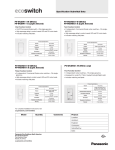
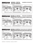
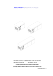
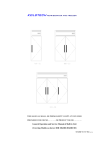
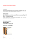
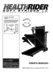
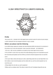
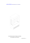
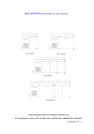
Ventilating Fan
Model No.
FV-11VH2
FV-11VH2
FV-11VHL2
FV-11VHL2
Thank you very much for having purchased our Ventilating Fan.
I
II
III
Maintenance I (Cleaning)
Maintenance II (Replacement of lamp)
back cover
back cover
UNPACKING
Unpack and carefully remove unit from carton.
Refer to the Supplied Accessories list to verify that all parts are present.
SUPPLIED ACCESSORIES
FOR MODEL FV-11VH2
FOR MODEL FV-11VH2
POURLE MODELE FV-11VHL2
POURLE MODELE FV-11VHL2
DESCRIPTION
The Panasonic ceiling mount ventilating fans uses a sirocco fan driven by a capacitor motor. The motor is
designed to have an extended service life with reduced energy consumption. It also incorporates a
thermal cut-off for safety. The grille covering the main body is a spring-loaded, quick-release type. A
damper for preventing counterflow is provided. The blower uses a high-capacity sirocco fan developed to
reduce the noise level.
The heater for this unit is a 1400 W sheathed heater. A thermostat and thermal cut-off switch have been
added for safety in case of an abnormal temperature rise in the heater.
The lighting unit is an energy-saving, lighting device which uses two 18 W fluorescent lamps and produces
almost the same illumination as a standard 100 W incandescent lamp (FV-11VHL2).
7 5/8 (195)
Ventilating unit
2 1/2 (62)
5 (128.7)
11 1/4 (285.5)
2 1/8 (54.8)
7 3/4 (196)
7 5/8 (195)
14 (357.8)
11 7/8 (301)
11 1/4 (285.5)
13 1/4 (337.8)
11 7/8 (301)
2 1/2 (62)
1 (25)
7 3/4 (196)
DIMENSIONS
19 1/2 (497)
16 (407)
18 1/8 (460)
5 (128.7)
16 (407)
19 1/2 (497)
18 1/8 (460)
SPECIFICATIONS
Noise
Vent (0.1" WG)
(cfm)
Exhaust &
Circulation
29.5
Vent
(sone)
650
0.6
15.6
(7.1)
720
0.7
17.8
(8.1)
1540
GENERAL SAFETY INFORMATION
AC 120V, 60Hz.
8. Make sure that all duct work is properly vented.
9. DO NOT INSTALL THIS UNIT OVER A BATHTUB OR SHOWER ENCLOSURE.
10. This product (FV-11VHL2) has a fluorescent lamp that contains mercury. Disposal may be regulated in your
community due to environmental considerations. For disposal or recycling information, please contact your
local authorities or the Electronics Industries Alliance:http://www.eiae.org
Only for FV-11VHL2.
3. This product must be properly grounded.
GENERAL SAFETY INFORMATION CONTINUED
WARNING:
To reduce the risk of fire, electric shock or injury to persons, observe the following:
A. Use this unit only in the manner intended by the manufacturer. If you have any questions, please contact
the manufacturer.
B. Installation work and electrical wiring must be done by qualified person(s) in accordance with all applicable
codes and standards, including fire-rated construction. Neither unauthorized modification, repair nor
disassembly is allowed.
C. Sufficient air is needed for proper combustion and exhausting of gases through the flue (chimney) of fuel
buming equipment to prevent backdrafting. Follow the heating equipment manufacturer's guideline and
safety standards such as those published by the National Fire Protection Association (NFPA), and the
American Society for Heating Refrigeration and Air Conditioning Engineers (ASHRAE) and the local code
authorities.
D. When cutting or drilling into wall or ceiling, do not damage electrical wiring and other hidden utilities.
E. Ducted fans must always be vented to the outdoors.
F. Solid state controls may cause harmonic distortion which can cause motor humming noise. To reduce the
risk of fire or electric shock, do not use this unit with any solid-state control device.
G. Before servicing or cleaning unit, switch power off at service panel and lock panel cabinet to prevent
power from being switched on accidentally. If the panel cabinet cannot be locked, securely fasten a
clearly visible warning label to the service panel.
H. Never place a switch where it can be reached from a tub or shower.
I. Not to be installed in a ceiling thermally insulated to a value greater than R40. (This is required for
installation in Canada only.)
J. Use only on 20 ampere branch circuit.
WIRING DIAGRAM
White
Heater
(1400W)
Fuse Thermal
cut-off
o
o
Black (20A) (230 F (110 C))
Black
Motor(C) Red
White
PCB
Electronic
ballast
White
White
Ventilating fan unit
Red
Motor(V) White
Black
Heater
(1400W)
Thermostat
(140oF (60oC))
Thermostato
(140oF (60C))
Ventilating fan unit
Red
White Capacitor
Capacitor
Fluorescent lamp
Motor(V)
Black
White
Black
White
Black
ON
ON
White
OFF
ON
Black
ON
OFF
Black
White
White
Black
Black
Junction box
Night lamp
Junction box
Green
Power Supply
AC120V 60Hz
Power Supply
AC120V 60Hz
OFF
Switch(not
included)
OFF
Switch(not
included)
Switch(not
included)
Switch(not
included)
OFF
ON
OFF
ON
Switch(not
included)
Green
Earth ground
Black
Black
PCB
Thermal
cut-off
(230oF (110oC))
White
Black
Motor(C) Red
Lighting unit
Circulating fan unit
Fuse
(20A)
Fuse
(3.15A)
Circulating fan unit
Earth ground Power Supply Power Supply Power Supply
AC120V 60Hz AC120V 60Hz AC120V 60Hz
INSTALLATION (JOIST MOUNTING- )
Illustrations in this manual common use the image of
FV-11VHL2, and mark for FV-11VHL2 only, others are
same for FV-11VH2.
1. Before installation, remove warning lable and the tape
that is securing the adapter and the damper. (Fig.1)
Warning label
Suspension
bracket
Fan body
Suspension
bracket
Tape
Suspension
bracket
Fan body
Fig.2-1
Suspension
bracket
Fig.1
2. Insert the suspension bracket into the fan body.
(Select the suspension bracket as shown below.)
Fan body
Suspension
Suspension bracket
bracket
Fig.2-2
Suspension
bracket
Fan body
Joists
Joist
Fig.2-3
Fan body
16 inches and 19.2 inches
horizontal joists
Fig.3
4 Long screws (ST4.2X20)
2 Long screws
(ST4.2X20)
2 Screw (ST4.2X8)
Suspension bracket
Joist
Screw
(ST4.2X12)
Suspension bracket
Fig.4-1
Screw
(ST4.2X12)
(Fig.3)
Joist
16 inches and 19.2 inches
horizontal joists refer to Fig.4-1, 19.2 inches vertical
joists and 24 inches refer to Fig.4-2.
2 Long screws
(ST4.2X20)
Fig.4-2
INSTALLATION (JOIST MOUNTING- ) CONTINUED
5. Remove the lighting cord out from hook (FV-11VHL2),
then remove junction box plate and secure conduit or
stress relief to wiring box knock-out hole.(Fig.5)
6. Refer to wiring diagram (Page.5)
Follow all the local electrical safety codes. As well as
the National Electrical Code (NEC).
Using UL approved wire nuts, connect house power
wires to ventilating fan wires (Fig.6):
Black to black; white to white; green to green.
Make sure all connections are fastened firmly after
wiring is finished.
Replace the junction box plate, and then replace
lighting cord to hook. (Fig.5)
Screw driver
Junction box
plate
Lighting cord
Screw
Hook
Fig.5
Black to black
Junction box plate White to white
White to white
Black to black
Green to green
Wire nut
Black to black
Black to black
Junction box
White to white
Conduit
Fig.6
Circular duct
Conduit
Duct tape
or clamps
Fan body
Joist
Fig.7
4 Long screws (ST4.2X20)
9)
17 3/8 (441)
5/8
(31
7. Install the circular duct (4 inches) to the adaptor and
secure it with duct tape or clamps. (Fig.7)
12
Night lamp
8. Finish ceiling work. Ceiling hole should be aligned
with the edge of the flange. (Fig.8)
Fluorescent lamp
Slot
9. Install the fluorescent lamps and then install the
night lamp. (Fig.8)
10. Insert mounting springs into slots as shown and
mount grille to fan body. (Fig.9)
Note:Do not mount grille and springs conversely. If
the grille is mounted in the opposite direction,
the grille can not be fitted to the ceiling, so
then reverse the grille position and try to
mount again.
(Fig.10)
Fig.8
Mounting spring
Correct
Incorrect
Grille
Switch
labels
For Model FV-11VHL2
For Model FV-11VH2
Fig.9
Switch
labels
Fig.10
INSTALLATION
(BETWEEN JOIST MOUNTING)
Illustrations in this manual common use the image of
FV-11VHL2.
1. Before installation, remove warning lable and the tape
that is securing the adapter and the damper. (Fig.1)
Fig.11
(Select the suspension bracket according to spacing A
as shown below.)
Suspension
bracket
Fan body
Suspension
bracket
Suspension
bracket
B
Fig.11
Joists
B
Spacing A on center joists
16 inches
13 1/4 ~ 15 1/2 (336~394)
19.2 inches horizontal joists 14 3/4 ~ 16 3/4 (374~425)
19.2 inches vertical joists
Adaptor
16 1/2 ~ 18 3/4 (419~476)
Fan body
Junction box
Suspension bracket
Fig.12
Keep the distance C (1/2 inch, 12.7 mm) for the
thickness of ceiling board.
C
Fig.12
INSTALLATION
(BETWEEN JOIST MOUNTING) CONTINUED
Fig.13, Fig.14
Joist
2 Long screws
(ST4.2X20)
Fig.13
2-Screw
(ST4.2X12)
Fig.14
4 Long screws
(ST4.2X20)
Joist
6. Follow step 5 of installation
installation work.
(page 7) to complete the
Fig.14
INSTALLATION
(WOODEN HEADER INSTALLATION)
1. Before installation, remove warning lable and the tape
that is securing the adapter and the damper. (Fig.1)
Ceiling joist
11 3
/8 (
Header
Ceiling joist
290
)
/8
19 7
(505
)
Adaptor
(Fig.15, Fig.16)
Fan body
Fig.15
4. Follow step 5 of installation
installation work.
(page 7) to complete the
Adaptor
Circular
duct
Long screw (ST4.2X20)
Fig.16
MAINTENANCE
(CLEANING)
Slot
Mounting spring
Gloves
Grille
Do not allow any water to get into the motor.
60 oC(140 oF).
1
1
2
Fig.17
Fig.17
Fig.18
Fig.18
Fig.19
Vacuum cleaner
Fig.19
Fig.20
5. Replace grille.
Fig.20
MAINTENANCE
(REPLACEMENT OF LAMP)
4. Be sure to remove the night lamp before removing fluorescent lamps.
(Fig.17 of page 10)
2. Remove the 4 W night lamp.(Fig.21)
Night lamp
Fluorescent lamp
Fig.21
3. Change the fluorescent lamps (FDS18E35/4, 18 W)
(Fig.22) or the 4 W night lamp(Fig.21), replace the
grille.
Fluorescent lamp
Fig.22
PRACTICAL GUIDE TO INSTALLATION
Properly insulate the area around the fan to
Fig.23
Dryer-hood type vent with
backdraft flap (s).
Caulk termination to duct.
2-3 ft straight run before elbow.
In attic installation,
caulk box to drywall.
Short piece of flexible duct
helps alignment and absorbs
sound. Use clamps plus tape
at all flex joints.
Insulation
Foil tape tightly covers all metal
duct joints (glue PVC joints).
Fig.23
PANASONIC CONSUMER ELECTRONICS COMPANY
Division de Panasonic Corporation of North America,
One Panasonic Way, Secaucus, NJ 07094
www.panasonic.com
PANASONIC CANADA INC.
5770 Ambler Drive, Mississauga, ON L4W 2T3
www.panasonic.ca
X0308-0
11VH24200