1
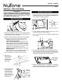
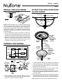
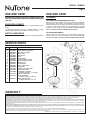
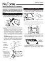
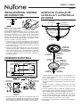
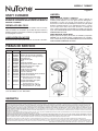
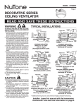
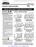
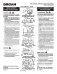
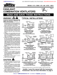
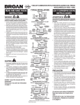
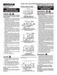
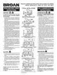
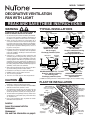
MODEL 745BNNT
Page 1
DECORATIVE VENTILATION
FAN WITH LIGHT
READ AND SAVE THESE INSTRUCTIONS
TYPICAL INSTALLATIONS
WARNING
TO REDUCE THE RISK OF FIRE, ELECTRIC SHOCK, OR
INJURY TO PERSONS, OBSERVE THE FOLLOWING:
1. Usethisunitonlyinthemannerintendedbythemanufacturer.Ifyouhavequestions,contactthemanufacturerat
theaddressortelephonenumberlistedinthewarranty.
2. Before servicing or cleaning unit, switch power off at
servicepanelandlocktheservicedisconnectingmeans
topreventpowerfrombeingswitchedonaccidentally.
Whentheservicedisconnectingmeanscannotbelocked,
securelyfastenaprominentwarningdevice,suchasa
tag,totheservicepanel.
3. Installationworkandelectricalwiringmustbedoneby
aqualifiedperson(s)inaccordancewithallapplicable
codesandstandards,includingfire-ratedconstruction
codesandstandards.
4. Sufficient air is needed for proper combustion and
exhaustingofgasesthroughtheflue(chimney)offuel
burningequipmenttopreventbackdrafting.Followthe
heatingequipmentmanufacturer’sguidelineandsafety
standardssuchasthosepublishedbytheNationalFire
ProtectionAssociation(NFPA),andtheAmericanSociety
forHeating,RefrigerationandAirConditioningEngineers
(ASHRAE),andthelocalcodeauthorities.
5. Whencuttingordrillingintowallorceiling,donotdamageelectricalwiringandotherhiddenutilities.
6. Ductedfansmustalwaysbeventedtotheoutdoors.
7. DONOTinstallinatuborshowerenclosure.
8. Thisunitmustbegrounded.
9. ThisunitisU.L.listed.TypeI.C.inherentlyprotected.
CAUTION
!
1. Forgeneralventilatinguseonly.Donotusetoexhaust
hazardousorexplosivematerialsandvapors.
2. ThisproductisdesignedforinstallationinFLATCEILINGS
ONLY.Donotmountthisproductinawall.
3. Thelightfixtureassemblymustbemountedtothefan
housing assembly included with this product. Do not
mountthelightfixtureassemblytoawiringoutletbox.
4. Toavoidmotorbearingdamageandnoisyand/orunbalancedimpellers,keepdrywallspray,constructiondust,
etc.offpowerunit.
5. Please read specification label on product for further
informationandrequirements.
Installer:
Leave this manual with the
homeowner.
Homeowner:
Use and Care information on page 4.
POWER CABLE
POWER CABLE
MOUNTING
TABS
MOUNTING TABS
ADDITIONAL
FRAMING
*
2x4
CEILING
JOIST or
TRUSS
CEILING
JOIST
2x4
CEILING
JOIST or
TRUSS
HOUSING
HOUSING
HOUSING
GRILLE
PAN
CEILING
MATERIAL
GLASS
LIGHT SHADE
GLASS
LIGHT SHADE
HOUSING MOUNTED
TO 2x4 TRUSS
Requires additional framing
for mounting tabs.
Discharge parallel to joists.
HOUSING MOUNTED
DIRECTLY TO JOIST
2x6 (or larger)
Discharge parallel to joists.
POWER CABLE
GRILLE
PAN
CEILING
MATERIAL
ADDITIONAL
FRAMING
*
MOUNTING
TABS
4" ROUND
DUCT
POWER
CABLE
HOUSING
"I "
JOIST CEILING
MATERIAL
GLASS LIGHT SHADE
HOUSING
"I "
JOIST
GRILLE
PAN
SUSPENDED
CEILING
MATERIAL
MOUNTING
TAB
GRILLE
PAN
GLASS
LIGHT SHADE
HOUSING MOUNTED TO “I” JOIST
Requires additional framing
SUSPENDED CEILINGS
for mounting tabs.
Housing hung with wires Discharge parallel to joists.
3-point mount.
* Additional framing must be a 2x6 (minimum height), at least 9-inches long.
PLAN THE INSTALLATION
INSULATION
(Place around and
over fan housing.)
ROOF CAP*
(with built-in
damper)
FAN
HOUSING
POWER
CABLE*
Seal gaps
around
housing.
Keep duct
runs short.
OR
4-IN. ROUND
DUCT*
Seal duct
joints with 4-IN. ROUND
*Purchase
tape.
separately.
ELBOWS*
WALL CAP*
(with built-in
damper)
MODEL 745BNNT
Page 2
INSTALL THE HOUSING
- PLEASE NOTE THE FOLLOWING INSTALLATION ILLUSTRATIONS SHOW 2 X
6 JOISTS. IF YOU HAVE A TRUSS OR “I”-JOIST INSTALLATION,
MOUNT THE VENTILATOR TO THE ADDITIONAL FRAMING IN
THE SAME MANNER. (Additional framing must be a 2x6 (minimum height), at least 9-inches long.)
Existing Construction
1. Choose the location for your fan/light in the ceiling. For best
possible performance, use the shortest possible duct run
and a minimum number of elbows.
New Construction
HOLES
TAB
1-1/4
1
5/8
BOTTOM EDGE OF JOIST
1. Choose the location for your fan in the ceiling. For best
possible performance, use the shortest possible duct run
and a minimum number of elbows.
2. Position mounting brackets against joist so that bottom
edge of housing will be flush with finished ceiling.
Additional positioning feature for 5/8”, 1”, &
1-1/4” thick ceiling material:
Holes in corners of housing are labeled with various
ceiling material thicknesses. Position housing so
bottom edge of joist is visible through a matched
set of holes. The housing is now in the proper
position for that ceiling material thickness.
Additional positioning feature for 1/2” thick
ceiling material:
Bend two tabs, on side of housing, 900 outward. Lift
housing until tabs contact underside of joist.
Mark the keyhole slot on both mounting brackets.
3. Set housing
aside and drive
nails partially
into joist at the
top of both keyhole marks.
2. In attic, position mounting brackets against joist. Trace
outline of housing on ceiling material.
3. Set housing aside and cut ceiling opening slightly larger
than marked.
4. Place housing in opening so that its bottom edge is flush
with finished ceiling. Nail to joist through keyhole on both
sides. To ensure a noise-free installation, drive another nail
through the top hole of each mounting bracket.
ADDITIONAL
MOUNTING
HOLES
5. Additional mounting holes are provided for installations
where access from above is inconvenient or not possible.
Nail or screw housing directly to joists or framing.
4. Hang housing from
nails and pound
nails tight. To ensure a noise-free
mount, pound another nail through
the top hole of each
mounting tab.
MODEL 745BNNT
Page 3
INSTALL THE DUCTWORK
FLUSH
ATTACH THE GRILLE PAN AND
GLASS SHADE
GRILLE PAN
LOCK
WASHER
GRILLE SCREW
COLLAR
ROD
NOTE: The duct connector has a counter-balanced damper
flap. The flap will be “open” approx. 1” when duct connector
is attached to housing. This design permits insulation to be
in direct contact with fan/light housing per UL (Underwriters
Laboratories) standards. The slightest backdraft, however,
will close the damper flap, preventing air from entering unit
or finished space.
1. Snap the damper/duct connector onto housing. Make sure
that tabs on the connector lock into slots in housing. Top of
damper/duct connector should be flush with top of housing.
2. Connect 4” round duct to damper/duct connector and
extend duct to outside through a roof or wall cap. Check
damper to make sure that it opens freely. Tape all duct
connections to make them secure and air tight.
CONNECT THE WIRING
RED
BLU
WHT
LIGHT
(WHITE)
VENT
SWITCH
BLK
BLK
WHT
VENT
(BLACK)
GRILLE
PAN
GLASS
SHADE
SCHEMATIC WIRING DIAGRAM
LIGHT
SWITCH
GLASS SHADE
BLK
WHT
LINE WHT
IN
GRD
60 WATT
MAX.
B10 TYPE
CANDELABRA
BULBS
LOCK
(2 REQ.)
WASHER
ROD
STEEL
WASHER
FELT
WASHER
(Add second
washer as
needed to
secure shade
tightly.)
GRD
UNIT
SWITCH BOX
DUAL CONTROL
(purchase separately)
WASHERS
BLACK
RED
WHITE
GROUND
(bare)
BLUE
SWITCH BOX
WHITE
RECEPTACLE
(LIGHT)
BLACK
RECEPTACLE
(FAN)
LIGHT
FAN
WIRING
PLATE
120 VAC
LINE IN
1. Wire unit following diagram above. Run electrical cable as
direct as possible to unit. Do not allow cable to touch sides
or top of unit after installation is complete.
FINIAL
NUT
FINIAL
CAP
1. Locate the grille pan over the fan housing and connect the
wiring harness plug into white receptacle in the fan housing.
2. Insert rod through center hole of grille pan. Use lock washer
between collar on rod and pan.
3. Thread rod onto grille screw in housing, until pan is tight
against ceiling. Do not over-tighten mounting rod.
4. Install bulbs. Use 60-watt (maximum), B10 type, candelabra
bulbs or energy-efficient equivalent bulbs with an M.O.L. of
4.8 inches or less.
5. Place washers and glass shade over mounting rod and align
shade over grille pan. Secure glass shade to mounting rod
with steel and felt washers and finial cap and nut as shown.
6. Restore electrical power and check operation of the unit.
MODEL 745BNNT
Page 4
USE AND CARE
USE AND CARE
WARNING: DISCONNECT ELECTRICAL POWER SUPPLY AND
LOCK OUT SERVICE PANEL BEFORE CLEANING OR SERVICING
THIS UNIT.
CLEANING
BULB REPLACEMENT
Remove glass shade. Replace bulbs as required. Replace glass
shade.
Use 60 Watt (maximum), B10 type, candelabra bulbs or energyefficient equivalent bulbs with an M.O.L. of 4.8 inches or less.
MOTOR LUBRICATION
The motor is permanently lubricated. Do not oil or disassemble motor.
TO CLEAN GLASS SHADE AND GRILLE PAN:
Remove glass shade. Shade can be wiped clean with a mild detergent solution or glass cleaner and dried with a soft cloth. Remove
2 bulbs. Grille pan may be gently vacuumed and wiped clean with
a soft cloth. Never use abrasive cloth, steel wool pads or scouring
powders on glass shade or grille pan. METAL AND ELECTRICAL
PARTS SHOULD NEVER BE IMMERSED IN WATER.
TO CLEAN FAN ASSEMBLY:
Remove grille pan and unplug fan assembly (black receptacle).
Gently vacuum fan, motor and interior of housing. METAL AND
ELECTRICAL PARTS SHOULD NEVER BE IMMERSED IN WATER.
SERVICE PARTS
KEY PART NO.
1
2
3
4
5
6
7
8
9
10
11
12
13
14
15
A
99523639
97018634
99260425
97018311
99150583
99080669
99020300
99270981
99270982
98009612
99150471
99170245
98008868
97014185
97014922
97018629
B
C
97018732
97018731
D
97015171
15
14
DESCRIPTION
Glass Shade
Shade Mounting Hardware
Motor Nut, Hex Keps
Motor Plate
Grille Screw
Motor
Blower Wheel
Lamp Receptacle, White
Motor Receptacle, Black
Wiring Panel
Ground Screw
Screw, #8-18 X 3/8”
Wiring Plate
Damper / Duct Connector
Housing Assembly
Light Fixture Assembly
(Includes Key Nos. 1, 2 and B)
Grille Pan Assembly
Blower Assembly
(Includes Key Nos. 3 thru 7)
Wire Panel Assembly
(Includes Key Nos. 8, 9, 10)
B
D
10
13
11
12
9
8
7
A
2
C
6
5
4
Order replacement parts by “PART NO.” - not by “KEY NO.”
1
2
3
WARRANTY
BROAN-NUTONEONEYEARLIMITEDWARRANTY
Broan-NuTonewarrantstotheoriginalconsumerpurchaserofitsproductsthatsuchproductswillbefreefromdefectsinmaterialsorworkmanshipforaperiodofoneyearfromthedateoforiginalpurchase.
THEREARENOOTHERWARRANTIES,EXPRESSORIMPLIED,INCLUDING,BUTNOTLIMITEDTO,IMPLIEDWARRANTIESOFMERCHANTABILITYORFITNESSFORAPARTICULARPURPOSE.
Duringthisone-yearperiod,Broan-NuTonewill,atitsoption,repairorreplace,withoutcharge,anyproductorpartwhichisfoundtobedefectiveundernormaluseandservice.
THISWARRANTYDOESNOTEXTENDTOFLUORESCENTLAMPSTARTERS,TUBES,HALOGENANDINCANDESCENTBULBS,FUSES,FILTERS,DUCTS,ROOFCAPS,WALLCAPSANDOTHERACCESSORIES
FORDUCTING.Thiswarrantydoesnotcover(a)normalmaintenanceandserviceor(b)anyproductsorpartswhichhavebeensubjecttomisuse,negligence,accident,impropermaintenanceorrepair(other
thanbyBroan-NuTone),faultyinstallationorinstallationcontrarytorecommendedinstallationinstructions.
Thedurationofanyimpliedwarrantyislimitedtotheone-yearperiodasspecifiedfortheexpresswarranty.Somestatesdonotallowlimitationonhowlonganimpliedwarrantylasts,sotheabovelimitation
maynotapplytoyou.
BROAN-NUTONE’SOBLIGATIONTOREPAIRORREPLACE,ATBROAN-NUTONE’SOPTION,SHALLBETHEPURCHASER’SSOLEANDEXCLUSIVEREMEDYUNDERTHISWARRANTY.BROAN-NUTONESHALL
NOTBELIABLEFORINCIDENTAL,CONSEQUENTIALORSPECIALDAMAGESARISINGOUTOFORINCONNECTIONWITHPRODUCTUSEORPERFORMANCE.Somestatesdonotallowtheexclusionorlimitation
ofincidentalorconsequentialdamages,sotheabovelimitationorexclusionmaynotapplytoyou.
Thiswarrantygivesyouspecificlegalrights,andyoumayalsohaveotherrights,whichvaryfromstatetostate.Thiswarrantysupersedesallpriorwarranties.
Toqualifyforwarrantyservice,youmust(a)notifyBroan-NuToneattheaddressortelephonenumberbelow,(b)givethemodelnumberandpartidentificationand(c)describethenatureofanydefectinthe
productorpart.Atthetimeofrequestingwarrantyservice,youmustpresentevidenceoftheoriginalpurchasedate.
Broan-NuToneLLC,926W.StateStreet,Hartford,Wisconsin53027www/broan.com800-558-1711
99044766B
MODELO 745BNNT
Página 5
VENTILADOR DECORATIVA
CON LA LUZ
LEA Y CONSERVE ESTAS INSTRUCCIONES
ADVERTENCIA
INSTALACIONES TÍPICAS
PARA REDUCIR EL RIESGO DE INCENDIO, DESCARGA ELÉCTRICA O LESIONES PERSONALES, OBSERVE LO SIGUIENTE:
1. Utiliceestaunidadsolamentedeacuerdoconlasinstrucciones
delfabricante.Sitienepreguntascomuníqueseconelfabricante
aladirecciónoalnúmerotelefónicoqueseindicaenlagarantía.
2. Antesdedarservicioolimpiarlaunidad,interrumpaelsuministro
deenergíaenelpaneldeservicioybloqueelosdispositivosde
desconexiónparaevitarlareinstalaciónaccidentaldelaenergía.
Cuandonosepuedanbloquearlosdispositivosdedesconexión,
fijeseguramenteenelpaneldeserviciounmediodeadvertencia
queseavisible,comoporejemplounaetiqueta.
3. Unapersonaopersonascalificadasdebenrealizareltrabajode
instalaciónyelcableadoeléctrico,deacuerdocontodoslos
códigosynormasaplicables,inclusiveloscódigosynormas
deconstrucciónparaevitarincendios.
4. Senecesitasuficienteaireparaqueserealicelacombustión
yladescargadegasesadecuadasatravésdelachimeneadel
equipoparaquemarcombustibleafindeevitarlascorrientes
deinversión.Observeloslineamientosdelfabricantedelequipo
decalefacciónylasnormasdeseguridad,comoporejemplo
laspublicadasporlaAsociaciónNacionaldeProteccióncontra
Incendios (National Fire Protection Association: NFPA), y la
SociedadAmericanadeIngenierosenCalefacción,Refrigeración
ySistemasdeAcondicionamientodeAire(AmericanSocietyfor
Heating,RefrigerationandAirConditioningEngineers:ASHRAE),
y los códigos locales.ditioning Engineers (ASHRAE), y las
autoridadesdeloscódigoslocales.
5. Cuandocorteoperforelaparedoelcieloraso,tengacuidadode
nodañarelcableadoeléctriconiotrasconexionesdeservicios
queseencuentrenocultas.
6. Losventiladoresconconductossiempredebentenersalidahacia
elexterior.
7. NOinstaleelaparatoenunacajadebañeraoducha.
8. Estaunidadsedebeconectaratierra.
9. EstaunidadestáincluidaenlalistadeU.L.TipoI.C.proteger
inherente.
PRECAUCIÓN
!
1. Esta unidad debe usarse solamente para ventilación general.
Nolautiliceparaladescargadematerialesnivaporespeligrosos
oexplosivos.
2. EsteproductoestádiseñadoSOLAMENTEPARAINSTALARSE
ENELCIELORASO.Nomonteesteproductoenlapared.
3. Elconjuntodelaluzsedebemontaralmontajedelacubierta
delventiladorincluidoconesteproducto.No monte el conjunto
de la luz a una caja del enchufe del cableado.
4. Paraevitarcausardañoaloscojinetesdelmotorypistones
impulsores ruidosos y/o no balanceados, mantenga los
aerosoles para pirca, el polvo de construcción, etc. lejos del
motor.
5. Por favor consulte la información y los requerimientos
adicionalescontenidosenlaetiquetadeespecificacionesque
seencuentraenelproducto.
A la persona que realiza la instalación:
Deje este manual con el dueño de la casa.
Al dueño de la casa:
Las instrucciones de operación y limpieza se
encuentran en la página 12.
*
CUBIERTA MONTADA
DIRECTAMENTE EN LA VIGUETA
2x6 (o más grande).
Descarga paralela a las viguetas.
*
CUBIERTA MONTADA
EN UNA VIGUETA “I”
Se requiere una estructura
adicional para las aletas de
montaje. Descarga paralela a
las viguetas.
CUBIERTA MONTADA
EN UNA VIGA DE 2x4
Se requiere una estructura
adicional para las aletas de
montaje. Descarga paralela a
las viguetas.
TECHOS SUSPENDIDOS
Cubierta montada con cables.
Montaje de tres puntos.
* Laestructuraadicionaldebeseruntramode2x6(alturamínima),dealmenos9pulgadas(23cm)delargo.
PLANIFICACIÓN DE LA INSTALACIÓN
AISLAMIENTO
(Puede ser colocado
alrededor y sobre de la
cubierta del ventilador.)
TAPA DE
TECHO*
(con
amortiguador
integral)
CUBIERTA DE
VENTILADOR
CABLE DE
ALIMENTACIÓN*
Selle los
huecos alrededor
de la cubierta.
Mantenga
corre
conducto
corto.
O
CONDUCTO REDONDO
DE 4 PULG. * Sellar las juntas
con cinta.
*Se compran
CODO REDONDO
por separado.
DE 4 PULG.*
TAPA DE
PARED*
(con amortiguador
integral)
MODELO 745BNNT
Página 6
INSTALACIÓN DE LA CUBIERTA
- POR FAVOR NOTE LAS SIGUIENTES ILUSTRACIONES DE LA INSTALACIÓN MUESTRAN
VIGUETAS DE 2 X 6. SI LA INSTALACIÓN ES EN UNA VIGA O EN
UNA VIGUETA EN “I”, MONTE EL VENTILADOR EN LA ESTRUCTURA
ADICIONAL DE LA MISMA MANERA. (La estructura adicional debe
ser un tramo de 2x6 (altura mínima), de al menos 9 pulgadas (23 cm)
de largo.)
Construcción existente
1. Seleccione la ubicación del ventilador con lámpara en el cielo
raso. Para obtener el mejor rendimiento posible, utilice un tramo
de conductos lo más corto posible y un número mínimo de codos.
Construcción nueva
1. Seleccione la ubicación del ventilador con lámpara en el cielo
raso. Para obtener el mejor rendimiento posible, utilice un tramo
de conductos lo más corto posible y un número mínimo de codos.
OROFICIOS
2. En el entretecho, coloque las abrazaderas de montaje contra la
vigueta. Trace el perímetro de la cubierta en el material del techo.
ALETA
1-1/4
1
5/8
3. Coloque la cubierta a un lado y haga una abertura en el techo
ligeramente más grande que el perímetro marcado.
BORDE INFERIOR DE LA VIGUETA
2. Coloque las abrazaderas de montaje contra la vigueta, de manera
que el borde inferior de la cubierta quede al ras del cielo raso
terminado.
Característica adicional para la colocación en material de
cielo raso de 5/8” (1.6 cm), 1” (2.5 cm) y 1 ¼” (3.2 cm):
Los orificios que se encuentran en las esquinas de la
cubierta están marcados con varios espesores del material
del cielo raso. Coloque la cubierta de manera que el borde
inferior de la vigueta sea visible a través del conjunto de
orificios que coinciden. Ahora la cubierta se encuentra en
la posición adecuada para ese espesor del material del
cielo raso.
Característica adicional para la colocación en material de
cielo raso de ½” (1.3 cm):
Doble a 90° y hacia afuera las dos aletas que se encuentran a
los costados de la cubierta. Levante la cubierta hasta que las
aletas entren en contacto con la cara inferior de la vigueta.
Marque el orificio con forma de cerradura de ambas abrazaderas
de montaje.
3. Coloque la
cubierta a un
lado e introduzca
parcialmente
los clavos en la
vigueta, en la
parte superior de
ambas marcas
de los orificios en
forma de cerradura.
4. Suspenda la cubierta con los clavos e
introduzca los clavos
completamente. Para
asegurar un montaje
sin ruido, coloque
otro clavo en el orificio superior de cada
aleta de montaje.
4. Coloque la cubierta en la abertura de manera que su borde
inferior quede al ras del cielo raso terminado. Clave la cubierta en
la vigueta a través del orificio en forma de cerradura, en ambos
lados. Para asegurar un montaje sin ruido, coloque otro clavo
en el orificio superior de cada aleta de montaje.
ORIFICIOS DE
MONTAJE
ADICIONALES
5. En la cubierta se pueden encontrar orificios de montaje adicionales
para aquellas instalaciones en las que es inconveniente o
imposible el acceso desde arriba. Clave o atornille la cubierta
directamente en las viguetas o el armazón.
MODELO 745BNNT
Página 7
INSTALACIÓN DEL SISTEMA
DE CONDUCTOS
AL RAS
ACOPLE EL PLATILLO DE
LA REJILLA Y LA PANTALLA
DE VIDRIO
PLATILLO
DE LA REJILLA
NOTA: El conector del conducto
tiene una aleta compensadora
para el regulador de tiro La aleta
estará “abierta” aproximadamente 1” (2.5 cm) cuando el conector
del conducto se sujete a la cubierta. Este diseño permite que el
material de aislamiento esté en contacto directo con la cubierta
del ventilador con lámpara de acuerdo con las normas de UL
(Underwriters Laboratories). Sin embargo, la más ligera corriente
invertida cerrará la aleta del regulador de tiro, evitando así la entrada
de aire a la unidad o al espacio terminado.
1. Conecte a presión el conector del regulador de tiro/conducto en
la cubierta. Asegúrese de que las aletas del conector queden
fijas en las ranuras de la cubierta. La parte superior del conector del regulador de tiro/conducto debe quedar al ras de la parte
superior de la cubierta.
2. Conecte el conducto redondo de 4” (10.2 cm) en el conector del
regulador de tiro/conducto y extienda el conducto hasta el exterior
a través de una tapa de techo o de pared. Revise el regulador
de tiro para asegurarse de que abre libremente. Coloque cinta
en todas las conexiones de los conductos para asegurarlas y
hacerlas herméticas.
CONEXIÓN ELÉCTRICA
ARANDELA
DE SEGURIDAD
ROJO
COMM.
VENT.
NEGRO
NEGRO
LÍNEA
DE ENT. BLANCO
TIERRA
BLANCO
AZUL
PANTALLA
DE VIDRIO
PLATILLO
DE LA REJILLA
PANTALLA
DE VIDRIO
LAMP. B L A N C O
(BLNC.)
BLANCO
N E G R O VENT.
(NEG.)
COLLARÍN
VARILLA
DIAGRAMA ELÉCTRICO
COMM.
LAMP.
TORNILLO
DE LA REJILLA
TUERCA
DE REMATE
ARANDELAS
BULBOS DE
CANDELABRO,
TIPO DE B10,
60 VATIOS MÁXIMO
(SE REQUIEREN 2)
ARANDELA
DE SEGURIDAD
VARILLA
ARANDELA
DE ACERO
ARANDELA
DE FIELTRO
(agregue una
segunda arandela
según sea necesario,
para asegurar
la pantalla
firmemente)
TAPA
DE REMATE
TIERRA
UNIDAD
CAJA DE CONMUTADOR
NEGRO
ROJO
BLANCO
TIERRA
(desnudo)
AZUL
CONTROL DOBLE
(se vende por separado) CAJA DEL CONMUTADOR
RECEPTÁCULO
BLANCO (LAMP.)
RECEPTÁCULO
NEGRO (VENT.)
1. Coloque el platillo de la rejilla sobre la caja del ventilador y conecte el enchufe del arnés de cables en el receptáculo blanco
de la caja del ventilador.
2. Introduzca la varilla por el orificio central del platillo de la rejilla.
Coloque la arandela de seguridad entre el collar de la varilla y
el platillo.
3. Enrosque la varilla en el tornillo de la rejilla de la caja hasta
apretar el platillo contra el techo. No apriete en exceso la varilla
de montaje.
LAMP.
VENT.
PLACA DE
CONEXIONES
LÍNEA DE ENTRADA
DE 120 VCA
1. Conecte la unidad de acuerdo con este diagrama. Extienda el
cable eléctrico a la unidad tan directamente como sea posible.
No permita que el cable toque los costados ni la parte superior
de la unidad después de que la instalación esté terminada.
4. Instale las bombillas. Utilice los bulbos de candelabro, tipo de
B10, 60 vatios máximo o bombillas eficientes equivalente a un
M.O.L. (longitud total máxima) de 4,8 pulgadas o menos.
5. Coloque las arandelas y la pantalla de vidrio sobre la varilla de
montaje y alinee la pantalla sobre el platillo de la rejilla. Fije la
pantalla de vidrio sobre la varilla con arandelas de acero y fieltro
y la tuerca remate y tapa de remate, como se ilustra.
6. Restablezca la energía eléctrica y compruebe el funcionamiento
de la unidad.
MODELO 745BNNT
Página 8
USO Y CUIDADO
ADVERTENCIA: DESCONECTE LA CORRIENTE ELECTRICA Y
BLOQUEE EL TABLERO DE SERVICIO ANTES DE LIMPIAR OR
REPARAR LA UNIDAD.
REEMPLAZO DEL FOCO
Quite la pantalla de vidrio. Reemplace los bulbos como necesarios.
Utilice los bulbos de candelabro, tipo de B10, 60 vatios máximo o
bombillas eficientes equivalente a un M.O.L. (longitud total máxima)
de 4,8 pulgadas o menos.
LUBICACIÓN DEL MOTOR
El motor lleva lubricación permanente. No lo enaceite o desarme.
LIMPIEZA
PARA LIMPIAR EL LENTE Y LA REJILLA:
Saque la tuerca de remate y sombrerete y quite la platalla. La
cortinilla puede limpiarse con una ligera solución detergente o
limpiavidrio y secarse con un trapo suave. Saque los 4 focos y
desconecte el enchufe del portalámpara. El tacho de rejilla puede
limpiarse cuedadosamente con la aspiradora de polvo y secarse
con un trapo suave. Nunca unse telas abrasivas o estropajo de
acero o polvos para frejar cuando limpie la cortinilla o el tacho de
rejilla. LAS PIEZAS METALICAS Y ELECTRICAS NUNCA DEBEN
SUMERGIRSE EN AGUA.
PARA LIMPIAR EL VENTILADOR:
Saque la placa de la rejilla y desenchufe el ventilador (receptáculo
NEGRO). Con la aspiradora limpie cuidadosamente el ventilador,
motor, e interior de la caja. LAS PIEZAS METALICAS Y ELECTRICAS
NUNCA DEBEN SUMERGIR EN AGUA.
PIEZAS DE SERVICIO
CLAVE PIEZA N.º
1
2
3
4
5
6
7
8
9
10
11
12
13
14
15
A
99523639
97018634
99260425
97018311
99150583
99080669
99020300
99270981
99270982
98009612
99150471
99170245
98008868
97014185
97014922
97018629
B
C
97018732
97018731
D
97015171
15
14
DESCRIPCIÓN
Pantalla de vidrio
Herrajes de montaje de la pantalla
Tuerca para motor, hexagonal Keps
Placa del motor
Tornillo de la rejilla
Motor
Rueda del soplador
Receptáculo de la lámpara, blanco
Receptáculo del motor, negro
Panel de cableado
Tornillo de puesta a tierra
Tornillo, #8-18 x 3/8 pulg.
Placa de cableado
Conector del regulador de tiro/conducto
Conjunto de la cubierta
Conjunto del accesorio de la luz
(incluye claves n.° 1, 2 y B)
Conjunto del platillo de la rejilla
Conjunto del ventilador
(incluye claves n.° 3 a 7)
Conjunto del panel de cableado
(incluye claves n.° 8, 9, 10)
B
D
10
13
11
12
9
8
7
A
2
C
6
5
4
Pida piezas de repuesto dando como referencia
el N°. DE PIEZA, no el N°. DE CLAVE.
1
2
3
GARANTIA
GARANTÍABROAN-NUTONELIMITADAPORUNAÑO
Broan-NuTonegarantizaalconsumidorcompradororiginaldesusproductosquedichosproductoscarecerándedefectosenmaterialesoenmanodeobraporunperíododeunañoapartirdelafechaoriginal
decompra.NOEXISTENOTRASGARANTÍAS,EXPLICITASOIMPLÍCITAS,INCLUYENDO,ENTREOTRAS,GARANTÍASIMPLÍCITASDECOMERCIALIZACIÓNOAPTITUDPARAUNPROPÓSITOPARTICULAR.
Duranteelperíododeunaño,yasupropiocriterio,Broan-NuTonerepararáoreemplazará,sincostoalguno,cualquierproductoopiezaqueseencuentredefectuosabajocondicionesnormalesdeservicioyuso.
LAPRESENTEGARANTÍANOCUBRELOSTUBOSFLUORESCENTESNISUSARRANCADORES,BOMBILLASDEHALÓGENOEINCANDESCENTES,FUSIBLES,FILTROS,CONDUCTOS,TAPONESDETECHOO
PAREDESYDEMÁSACCESORIOSPARACONDUCTOS.Estagarantíanocubre(a)mantenimientoyservicionormaleso(b)cualesquieraproductosopiezasquehayansidoutilizadosdeformaerrónea,negligente,
quehayancausadounaccidente,oquehayansidoreparadosomantenidosinapropiadamente(porotrascompañíasquenoseanBroan-NuTone),instalacióndefectuosa,oinstalacióncontrariaalasinstrucciones
deinstalaciónrecomendadas.
Laduracióndecualquiergarantíaimplícitaselimitaaunperíododeunañocomoseespecificaenlagarantíaexpresa.Algunosestadosnopermitenlimitacionesencuantoaltiempodevencimientodeunagarantía
implícita,porloquelalimitaciónantesmencionadapuedenoaplicarseausted.
LAOBLIGACIÓNDEBROAN-NUTONEDEREPARAROREEMPLAZAR,SIGUIENDOELCRITERIODEBROAN-NUTONE,DEBERÁSERELÚNICOYEXCLUSIVORECURSOLEGALDELCOMPRADORBAJOESTA
GARANTÍA.BROAN-NUTONENOSERÁRESPONSABLEPORDAÑOSINCIDENTALES,CONSECUENTES,OPORDAÑOSESPECIALESQUESURJANARAÍZDELUSOODESEMPEÑODELPRODUCTO.Algunos
estadosnopermitenlaexclusiónolimitacióndedañosincidentalesoconsecuentes,porloquelalimitaciónantesmencionadapuedenoaplicarseausted.
Estagarantíaleproporcionaderechoslegalesespecíficos,yustedpuedetambiéntenerotrosderechos,loscualesvaríandeestadoaestado.Estagarantíareemplazatodaslasgarantíasanteriores.
Paracalificarparalagarantíadeservicio,usteddebe(a)notificaraBroan-NuTonealdomiciliooalnúmerodeteléfonoquesemencionaabajo,(b)darelnúmerodelmodeloylaidentificacióndelapieza,y
(c)describirlanaturalezadecualquierdefectoenelproductoolapieza.Enelmomentodesolicitarserviciocubiertoporlagarantía,usteddebedepresentaruncomprobanteconlafechaoriginaldecompra.
Broan-NuToneLLC,926W.StateStreet,Hartford,Wisconsin53027www.broan.com800-558-1711
99044766B