Transcript
4
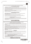
INSTALLATION INSTRUCTIONS FOR ONE-WAY / SINGLE TRAVERSE ROD (Drop In)
PARTS LIST
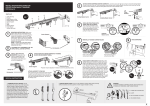
1. Pulley Housing
2. End Bracket
3. Inside Section of Rod
4. Outside Section of Rod
5. Center Support
6. Cord
7. Slide
8. Master Carrier
1
5
.1
Fig
1
4
5
3
1
2
6
7
TION
2
TU
4
LO
RN
Center Support
CK
!
Adjusting Screws
Projection may be adjusted, if needed, by loosening adjusting screws.
8
7
8
ONE WAY-CORD LEFT
MOUNTING INSTRUCTIONS:
Wall mount option- Mount the one
end bracket and one support to the
wall at desired location. No center
support is needed for installations
less than 50” long. Ceiling mount
option- If rod is to be installed to the
ceiling, attach pulley housing (without
brackets) and stirrup portion of center
support directly to the ceiling.
ATTACH SUPPORT TO THE ROD
The support arm goes over the top of the rod with
the silver cam lock toward the floor. The rod fits
into the arm hook and locks in by turning the cam
lock with a flat bladed screwdriver. Do not turn
the Philips screw.
JEC
PRO
3
2
ATTACH ROD INTO CENTER SUPPORT BY TURNING
SILVER COLOR BRACKET WHEEL.
End brackets
FOR RODS FULLY EXTENDED TO
50” OR MORE, INSTALL CENTER
SUPPORT.
6
ONE WAY-CORD RIGHT
Center Support
Center Support
5
7
REMOVAL OF UNUSED CARRIER SLIDES
HANG DRAPERIES
End brackets
1
2
3
Push up the end gate to remove carrier slides
ONE WAY-CORD LEFT
ONE WAY-CORD RIGHT
6
CHILD SAFETY CORD GUIDE: RODS WILL NOT WORK PROPERLY WITHOUT GUIDE INSTALLED
Guide is pre-attached to the cord. Mount the guide to the wall at the desired height using the included screw. Tighten the screw
until the cord slides through the device freely. (See Fig. 1) Remove excess slack on the cord by grasping and pulling down on the
knot that is on the back side of the master carrier. Pull the knot out until the cord is taught in the guide. Tie a new knot into the cord
as close as possible to the master carrier and cut off the excess cord. (See Fig. 2)
CHILD SAFETY CORD GUIDE REMOVAL: Pry open the three clips on the back of the device. (See Fig.3) Split the guide open
and remove the cord guide.
3
INSTALL ROD INTO END BRACKET: drop end
of rod into the u-shaped clip of the end bracket. To
remove rod from bracket simply lift the rod out of
the u-shaped clip.
Fig.
Spring clip
End bracket
Fig.
3
Knots
.1
Fig
Joining
Knot
SPECIAL INSTRUCTION
1. TENSION PULLEY OPTION: can be
mounted to the wall or floor. After securing
Tension Pulley to desired location, loop
cord onto pulley wheel. Grasp cord joining
knot behind Master Carrier and pull out
enough cord to take up slack between the
rod and the cord tension pulley. (Fig. 2)
Retie knot as close to the Master Carrier as
possible then cut off excess cord beyond
knot. Rotate pulley head until cords are in
proper alignment and release into pulley
base.
2
2. CEILING INSTALLATION. If rod is to be installed to ceiling, attach pulley housings
(without brackets) and stirrup portion of center support directly to ceiling.
Stirrup
cut
!
Overlap
Master Carrier
WARNING
TO AVOID POSSIBLE STRANGULATION, KEEP CORDS OUT
OF REACH OF CHILDREN. USE THESE DEVICES:
1. CLAMP OR CLOTHES PIN
2. CLEAT
3. TIE THE CORD TO ITSELF
4. TIE-DOWN DEVICE.
Pulley housing
Z