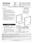
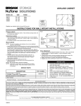
1
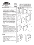
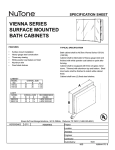
MODEL
NO.
MODEL:
Bisagra de 125 Grados
10
S168344
S268344
S235344
S368344
S335344
S468344
S435344
S568344
, S135344
, S268346
, S235346
, S368346
, S335346
, S468346
, S435346
, S568346
RECESSED MOUNTED, STEEL BATH CABINETS
Bisagra de 170 Grados
12
4.
INSTALLATION of CABINET
1. Carefully remove all packing material. Place hardware
5.
packages, shelves and door aside until needed.
2. Determine desired location of cabinet on wall. Mark wall
to show wall opening size (see dimension chart). Generally,
the recommended height to the center of the cabinet is 64”
from the floor. (Fig. 1)
3. CAUTION: Wall studs, plumbing or electrical lines that
interfere must be removed or relocated. Cut wall opening,
being careful not to damage the surrounding wall surface.
Inser t framing to support all plaster board edges.
6.
(Bisagra de 125 grados mostrada)
11
PIEZAS DE SERVICIO
Descripcion
1
Ensamblaje De la Puerta
2
Montaje de bisagra
3
Tornillo, bisagra
4
**Tapones
5
**Cubierta del tornillo
6
Tornillo de montaje #8 x 1 1/2*
7
**Soporte de estante
8
Estante de vidrio
9
Tira de Topes
10
Cubierta De la Bisagra (125 grados)
11
12
El Sujetador negro (170 grados)
Cierre Silencioso (170 gardos)
Key
No.
Descripcion
1
Ensamblaje De la Puerta
2
Montaje de bisagra
3
Tornillo, bisagra
4
Tapones
5
Cubierta del tornillo
6
Tornillo de montaje #8 x 1 1/2*
7
Soporte de estante
8
Estante de vidrio
9
Tira de Topes
10
Cubierta De la Bisagra (125 grados)
11
12
El Sujetador negro (170 grados)
Cierre Silencioso (170 gardos)
S168344
S135344
S268344
S268346
S235344
S235346
S368344
S368346
107-661-02
JRP595
10-163-01
29-826-xx
29-827-xx
*
29-842-xx
31-185-01
29-846-01
42-596-01
-
107-661-02P
JRP595
10-163-01
29-826-xx
29-827-xx
*
29-842-xx
31-185-01
29-846-01
42-596-01
-
107-662-02
JRP595
10-163-01
29-826-xx
29-827-xx
*
29-842-xx
31-185-01
29-846-01
42-596-01
-
107-662-02
JRP595
10-163-01
29-826-xx
29-827-xx
*
29-842-xx
31-186-01
29-846-01
42-596-01
-
107-662-02P
JRP595
10-163-01
29-826-xx
29-827-xx
*
29-842-xx
31-185-01
29-846-01
42-596-01
-
107-662-02P
JRP595
10-163-01
29-826-xx
29-827-xx
*
29-842-xx
31-186-01
29-846-01
42-596-01
-
107-663-02
JRP586D
10-163-01
29-826-xx
29-827-xx
*
29-842-xx
31-185-01
29-846-01
42-594-01
42-586-02
107-663-02
JRP586D
10-163-01
29-826-xx
29-827-xx
*
29-842-xx
31-186-01
29-846-01
42-594-01
42-586-02
S335344
S335346
S468344
S468346
S435344
S435346
S568344
S568346
107-663-02P
JRP586D
10-163-01
29-826-xx
29-827-xx
*
29-842-xx
31-185-01
29-846-01
42-594-01
42-586-02
107-663-02P
JRP586D
10-163-01
29-826-xx
29-827-xx
*
29-842-xx
31-186-01
29-846-01
42-594-01
42-586-02
107-665-02
JRP586D
10-163-01
29-826-xx
29-827-xx
*
29-842-xx
31-187-01
29-846-01
42-594-01
42-586-02
107-665-02
JRP586D
10-163-01
29-826-xx
29-827-xx
*
29-842-xx
31-192-01
29-846-01
42-594-01
42-586-02
107-665-02P
JRP586D
10-163-01
29-826-xx
29-827-xx
*
29-842-xx
31-187-01
29-846-01
42-594-01
42-586-02
107-665-02P
JRP586D
10-163-01
29-826-xx
29-827-xx
*
29-842-xx
31-192-01
29-846-01
42-594-01
42-586-02
LLAME COMPANIA
LLAME COMPANIA
JRP586D
10-163-01
29-826-xx
29-827-xx
*
29-842-xx
31-187-01
29-846-01
42-594-01
42-586-02
JRP586D
10-163-01
29-826-xx
29-827-xx
*
29-842-xx
31-192-01
29-846-01
42-594-01
42-586-02
W
WALL OPENING
H
D
14 ¼
14 ¼
14 ¼
14 ¼
14 ¼
14 ¼
14 ¼
14 ¼
14 ¼
14 ¼
14 ¼
14 ¼
14 ¼
14 ¼
14 ¼
14 ¼
34
34
34
34
34
34
34
34
34
34
34
34
34
34
34
34
W
4
4
4
6
4
6
4
6
4
6
4
6
4
6
4
6
15
15
15
15
15
15
15
15
15
15
15
15
15
15
15
15
OVERALL SIZE
H
D
35
35
35
35
35
35
35
35
35
35
35
35
35
35
35
35
Fig. 5
Snap on Cover
Inser t screw
through clear
plastic base
Cover
Screw
Base
Fig. 4
Fig. 3
Wall
Opening
Mounting
Screws
Cabinet
Body
Mounting
screw into
mounting
hole
* Ferreteria estandar - puede ser comprado localmente.
** Especifique (-01) blanco o (-02) negro donde "xx" se localiza
Pida los piezas de reemplazo por "NUMERO de PIEZA" - No por el "NUMERO DOMINANTE"
72-323-02D
8
1
5
5
5
7
5
7
5
7
5
7
5
7
5
7
5
7
Prepare the mounting screws by placing the screws into the
clear plastic bases. (Fig. 2)
Note: For ease of installation, an additional person is
recommended.Inser t cabinet into wall opening. (Fig.3) Ensure
the cabinet is plumb and level. If necessary use a carpenter’s
level and shim corners of cabinet. Secure the wall studs
through the four (4) mounting holes inside cabinet, using the
screws that have been placed into the plastic bases. (Fig. 4)
Do not over tighten the mounting screws as the body side wall
may bend and prevent proper shelf installation. Only tighten
until they are flush with the body.
Snap the screw covers over the screw bases. (Fig. 5)
Fig. 2
Fig. 1
Key
No.
S168344
S135344
S268344
S268346
S235344
S235346
S368344
S368346
S335344
S335346
S468344
S468346
S435344
S435346
S568344
S568346
INSTALLATION INSTRUCTIONS
ATTN: INSTALLER
DO NOT OVER TORQUE (TIGHTEN) HINGE MOUNTING SCREWS. MANUALLY SCREW IN WITH PHILLIPS SCREW DRIVER UNTIL
THE SCREW FEELS SECURE IN THE RIVET. IF USING A POWER DRILL, SET MAXIMUM TORQUE SETTING TO #5.
OVERTIGHTENING THE SCREWS MAY/WILL CAUSE THE RIVET NUT TO LOOSEN FROM THE UNDERSIDE.
FAMILIARIZE YOURSELF WITH HINGE PRIOR TO MOUNTING
INSTALLATION of DOORS
125 Degree Hinge
170 Degree Hinge
1. Remove hinges and screws from hardware bag.
Mount hinge unit on door as shown in Fig. 6
or Fig. 7 securing with screws provided.
The bar on the
2. Install the door by inserting door side of the
bottom of the
hinge into the bracket on the body as shown;
hinge slides
Bottom
Bottom
A) 125 degree hinge
into the slot on
view
view
Insert door side of clip hinge as shown in Fig. 8
the bracket.
B) 170 degree hinge
Insert door side of clip hinge as shown in Fig. 9
3. Check door for proper alignment. If the door needs
to be adjusted please refer to the adjustment
procedures in Fig. 10 or Fig. 11. Door edges
Press down to
should be aligned with to the face of the body.
snap into place.
4. A) 125 degree hinge only:
Snap on hinge cover plate. (Fig. 12)
B) 170 degree hinge only: (Fig. 13)
After proper alignment of door, REMOVE door
TO REMOVE HINGE
from body by unclipping each hinge. (see pg1)
Press in lever,
Place the door on a secure flat surface with the
then lift up on
hinges facing up. Use the diagrams in Figure 13 to
clip to release
apply the attachment to the top and bottom hinge.
hinge.
NOTE: Only TWO hinges need the attachment.
Only TWO attachments included.
(a) Improper mounting
Fig. 8
Fig. 7
Fig. 6
(b) Position soft close attachment into place.
125 Degree Hinge
170 Degree Hinge
125 Degree Hinge
(c) Slide hinge into place.
Mounted to Cabinet
Mounted to Door
Mounted to Door
(d) “Click” soft close attachment into place.
Hook bottom of hinge into
place on the bracket
C) Snap on the black limit clip.
D) Re-attach door to body as described in
Figure 11. Re-Check door for proper alignment.
Fig. 13
170 Degree Hinge
(a)
(b)
Press down on
hinge until it
clips in place
“Click”
(c)
(d)
Fig. 9
170 Degree Hinge
Mounted to Cabinet
Fig. 10
125 Degree Hinge
Hook bottom of hinge into
place on the bracket
This screw for
up and down
adjustments
This screw
for depth
adjustment
This screw adjusts door closure
Limit Clip
Instructions to remove soft close hinge attachment
This screw for left and right
adjustment
Press down on
hinge until it
clips in place
1) Remove door from body by unclipping each hinge. Place Fig. 11
This screw for up
Fig. 12
the door on a secure flat surface with the hinges facing up. 170 Degree Hinge and down adjustments 125 Degree Hinge
2) Using a flat screwdriver, position under triangle as shown.
3) Gently lift to remove hinge attachment.
Hinge Cover
This screw
for depth
adjustment
This screw for left and right adjustment
2
INSTALACION de ESTANTES Y TAPONES
Fig. 14
Fig. 15
Nota: Revise detenidamente la ubicacion deseada
para el estante. Los tapones de los hoyos son
dificiles de quitar una vez metidos, es importante
localizar la ubicacion del estante antes de instalar los
tapones.
1. Seleccione el lugar deseado de los estantes.
2. Ponga dos (2) soportes a cada lado de la ubicacion
deseada. (Fig. 14)
3. Ponga los estantes sobre los soportes, presione
y asi quedara el estante fijo en su lugar.
(Fig.14)
4. Saque los tapones de la bolsa y
coloquelos en los agujeros
restantes. (Fig. 15)
•
•
•
•
•
MIRROR
CARE
CUIDADO
DEL
ESPEJO
Utilice solamente agua tibia y un trapo limpio,
suave y sin pelusa.
No utilize limpiadores con solucion a base de
ammoniaco, vinagre o cloro.
No utilize limpiadores en polvo o fibras de
acero.
Nunca rocie el limpiador directamente en el
espejo, especialmente en los bordes y la
cubierta el la parte posterior. Aplique el
limpiador al trapo y limpie. Seque a fondo.
Mantenga el espejo seco. Un bano bien
ventilado es importante.
GARANTIA LIMITADA DE NUTONE DE UN ANO
NuTone le garantiza al consumidor comprador original de sus productos que tales productos estaran libres de
defectos en materiales o mano de obra por un periodo de un ano a partir de la fecha de compra original.
No hay otras garantias explicitas o implicitas, incluyendo, pero no limitadas a garantias implicitas de
comercialization o aptitud para un proposita particular.
Durante este periodo de un ano, NuTone reparara o cambiara, a su opcion y sin cobro, cualquier producto o
pieza que se encuentre defectuosa bajo uso y servicio normal.
Esta garantia no cubre (a) mantenimiento y servicio normales o (b) cualquier producto o pieza que hayan sido
sometidos a uso equivocado, negligencia, accidente, mantenimiento o reparacion indebida (excepto por
NuTone), instalacion defectuosa o instalacion contraria a las instrucciones de instalacion.
La duracion de cualquier garantia implicita se limita a un periodo de un ano segun se especifica en la qarantia
explicita. Algunos estados no permiten limitacion a la duracion de una garantia implicita, por lo que esta
limitacion tal vez no se aplica al caso suyo.
La obligacion de NuTone de reparar o cambiar, a opcion de NuTone, sera e unico y exclusivo remedio al
comprador bajo esta garantia. NuTone no sera responsable por danos incidentales, consecuentes, o
especiales que surjan de o en relacion a el uso o desempeno del producto. Algunos estados no permiten la
exlusion o limitacion de danos incidentales o consecuentes, por lo que esta limitacion o exclusion tal vez no se
aplica en su caso.
Esta garantia le da derechos legales especificos, y usted puede tener otros derechos que varian de estado a
estado. Esta garantia reemplaza todas las garantias anteriores.
Para calificar para servicio bajo esta garantia, usted debe (a) notificar a NuTone en la direccion que aparece
abajo o al telefono 1-800-325-8351, (b) dar el numero de modelo y la identificacion de pieza y (c) describir el
defecto en el producto o pieza. Al solicitar servicio bajo la garantia, usted debe presentar evidencia de la fecha
de compra original.
Broan-NuTone Storage Solutions 501 South Wilhite Cleburne, Texas 76031
(1-800-325-8351)
7
INSTRUCCIONES DE INSTALACION
NUMERO DE ABERTURA DE LA PARED
MODELO
ANCH
ALT
PROF
MODELO:
125 degree hinge
10
S168344
S268344
S235344
S368344
S335344
S468344
S435344
S568344
, S135344
, S268346
, S235346
, S368346
, S335346
, S468346
, S435346
, S568346
GABINETE DE ACERO EMPOTRADO EN LA PARED
170 degree hinge
12
11
INSTALACION del GABINETE
1. Quite cuidadosamente todo el material del empaquetado.
Coloque la puerta, los estantes y el paquete de herramientas
a un lado hasta que se necesite.
2. Determine el lugar en la pared para el gabinete.
Marque la pared para demostrar tamano de la abertura de
la pared (vease la grafica de dimensiones). Generalmente,
la altura recomendada son 163cm del centro del gabinete
hacia el suelo.
3. PRECAUCION: Lineas electricas o plomeria que
interfieran, deberan de ser removidas o colocadas en otro
lugar. Corte la abertura de la pared, con cuidado de no
danar la pared de alrededor. Meta o ponga el enmarco
para reforzar los bordes de yeso.
(125 degree hinge shown)
Fig. 1
SERVICE PARTS
Key
No.
Description
1
Door Assembly
2
Hinge Assy (Door)
3
Hinge Screw
S168344
S135344
S268344
S268346
S235344
S235346
S368344
S368346
107-661-02P
JRP595
10-163-01
29-826-xx
29-827-xx
*
29-842-xx
31-185-01
29-846-01
42-596-01
-
107-662-02
JRP595
10-163-01
29-826-xx
29-827-xx
*
29-842-xx
31-185-01
29-846-01
42-596-01
-
107-662-02
JRP595
10-163-01
29-826-xx
29-827-xx
*
29-842-xx
31-186-01
29-846-01
42-596-01
-
107-662-02P
JRP595
10-163-01
29-826-xx
29-827-xx
*
29-842-xx
31-185-01
29-846-01
42-596-01
-
107-662-02P
JRP595
10-163-01
29-826-xx
29-827-xx
*
29-842-xx
31-186-01
29-846-01
42-596-01
-
107-663-02
JRP586D
10-163-01
29-826-xx
29-827-xx
*
29-842-xx
31-185-01
29-846-01
42-594-01
42-586-02
107-663-02
JRP586D
10-163-01
29-826-xx
29-827-xx
*
29-842-xx
31-186-01
29-846-01
42-594-01
42-586-02
9
Bumpers
10
Hinge Cover (125 degree hinge)
11
12
Soft Close (170 degree hinge)
107-661-02
JRP595
10-163-01
29-826-xx
29-827-xx
*
29-842-xx
31-185-01
29-846-01
42-596-01
-
Key
No.
Description
S335344
S335346
S468344
S468346
S435344
S435346
S568344
S568346
107-663-02P
JRP586D
10-163-01
29-826-xx
29-827-xx
*
29-842-xx
31-185-01
29-846-01
42-594-01
42-586-02
107-663-02P
JRP586D
10-163-01
29-826-xx
29-827-xx
*
29-842-xx
31-186-01
29-846-01
42-594-01
42-586-02
107-665-02
JRP586D
10-163-01
29-826-xx
29-827-xx
*
29-842-xx
31-187-01
29-846-01
42-594-01
42-586-02
107-665-02
JRP586D
10-163-01
29-826-xx
29-827-xx
*
29-842-xx
31-192-01
29-846-01
42-594-01
42-586-02
107-665-02P
JRP586D
10-163-01
29-826-xx
29-827-xx
*
29-842-xx
31-187-01
29-846-01
42-594-01
42-586-02
107-665-02P
JRP586D
10-163-01
29-826-xx
29-827-xx
*
29-842-xx
31-192-01
29-846-01
42-594-01
42-586-02
CALL COMPANY
CALL COMPANY
JRP586D
10-163-01
29-826-xx
29-827-xx
*
29-842-xx
31-187-01
29-846-01
42-594-01
42-586-02
JRP586D
10-163-01
29-826-xx
29-827-xx
*
29-842-xx
31-192-01
29-846-01
42-594-01
42-586-02
4
Hole Plug
5
Screw Cover
6
Mounting Screw #8 x 1 1/2
7
Shelf Supports
8
Glass Shelf
Limit Clip (170 degree hinge)
1
Door Assembly
2
Hinge Assy (Door)
3
Hinge Screw
4
Hole Plug
5
Screw Cover
6
Mounting Screw #8 x 1 1/2
7
Shelf Supports
8
Glass Shelf
9
Bumpers
10
Hinge Cover (125 degree hinge)
11
12
Soft Close (170 degree hinge)
Limit Clip (170 degree hinge)
S168344
S135344
S268344
S268346
S235344
S235346
S368344
S368346
S335344
S335346
S468344
S468346
S435344
S435346
S568344
S568346
34
34
34
34
34
34
34
34
34
34
34
34
34
34
34
34
4
4
4
6
4
6
4
6
4
6
4
6
4
6
4
6
15
15
15
15
15
15
15
15
15
15
15
15
15
15
15
15
35
35
35
35
35
35
35
35
35
35
35
35
35
35
35
35
5
5
5
7
5
7
5
7
5
7
5
7
5
7
5
7
4. Prepare los tornillos de montaje colocando el tornillo
en la base de plastico. (Fig. 2)
5. Nota: Para mas facilidad en la instalacion, se
recomiendan dos personas. Meta el gabinete en la
abertura de la pared. (Fig. 3) Asegurese que este vertical
y al nivel. Si es necesario, rebaje las esquinas del gabinete.
Asegure la pared atravez de los cuatro (4) hoyos para
montar que se encuentran dentro deel gabinete usando los
tornillos que estan dentro de las bases de plastico. (Fig 4)
No apriete excesivamente los tornillos de montaje ya que
la parte lateral se puede doblar y prevenir la instalcion
adecuada de los estantes. Apriete hasta que los tornillos
esten parejos con el gabinete.
6. Encaje a presion las tapas sobre la cabeza del tornillo. (Fig.5)
Fig. 5
Fig. 2
Cubierta a presion
Meta el tornillo
atravez de la base
de plastico
transparente
Cubierta
Tornillo
Aproximadamente
163cm del piso
Base
Fig. 4
Fig. 3
Abertura
de la
pared
Tornillos
de
montaje
Cuerpo
del
gabinete
* Standard Hardware - may be purchased locally.
** Specify (-01) white or (-02) black where "xx" is located
Order Replacement parts by "Part Number" - not by "Key No."
4
14 ¼
14 ¼
14 ¼
14 ¼
14 ¼
14 ¼
14 ¼
14 ¼
14 ¼
14 ¼
14 ¼
14 ¼
14 ¼
14 ¼
14 ¼
14 ¼
TOMANO TOTAL
ANCH
ALT
PROF
5
Tornillos de
montaje en
el agujero
de montaje
ATENCION INSTALADORES:
De no apretar los tornillos de mas en la visagra , porfavor de aserlo manual mente con un desarmadorde crus hasta que usted piense que
esta seguro. Si usted husa un taladro sin cable apliquelo en el numero #5. Apretandolos tornillos demasiado apretado podra safarse el tornillo
de abajo.
INSTALACION de PUERTAS
1. Saque las bisagras y tornillos de la bolsa. Monte la
FAMILIARICEZE CON LA BISAGRA ANTES DE MONTARLA.
bisagra en la puerta de acuerdo a la Fig.6 o Fig.7
Bisagra de 125 Grados
Bisagra de 170 grados
usando los tornillos proporcionados.
2. Instale la puerta metiendo el lado de la puerta de la
La barra en la
bisagra dentro del soporte de acuerdo con lo
parte de abajo de
demostrado.
la bisagra se
A) Bisagra de 125 grados. Meta el lado de la puerta
Vista
Vista
resbala en la
de la bisagra segun la Fig. 8
inferior
inferior
ranura del
B) Bisagra de 170 grados. Meta el lado de la puerta
soporte
de la bisagra segun la Fig. 9
3. Asegurese que la alineacion sea adecuada. Si la
puerta necesita un ajuste, por favor vea la Fig. 10 o
Presione pare
Fig. 11 para los procedimientos. Los bordes de la
ponerlo en el
puerta deben de alinear con la caratula del gabinete.
lugar
4. A) Bisagra de 125 grados solamente: Ponga y
presione la cubierta de la bisagra. (Fig. 12)
B) Bisagra de 170 grados solamente: (Fig. 13)
PARA QUITAR LAS BISAGRAS
Despues de alinear la puerta, quite la puerta
quitando las bisagras. Ponga la puerta en una
Presione el
superficie segura y plana con las bisagras hacia
nivelador despues
arriba. Use los diagramas en la Figura 13 para
levante el clip
poner la pieza adjunta de cierre silencioso a
para liberar la
las bisagras de arriba y abojo.
bisagra
NOTA: Solo DOS bisagras ocupan la pieza adjunta.
Fig. 8
Fig. 7
Fig. 6
Solo DOS piezas adjuntas incluidas.
Bisagra de 125 grados
Bisagra
de
170
grados
Bisagra
de
125
grados
(a) Montura inapropiada
montada en el gabinete
montada a la puerta
montada a la puerta
(b) Ponga la pieza andjunta en su lugar
Ajuste la parte inferior
(c) Meta la bisagra en su lugar
de la bisagra en el soporte
(d) Presione la pieza adjunta en su lugar
(C) Presione el sujetador negro.
(D) Vuelva a instalar la puerta en el gabinete como
lo muestra la Figura 11. Asegurese que la
alineacion sea apropiada.
Fig. 13
(a)
Fig. 14
Fig. 15
Note: Carefully review the shelf location desired.
The hole plugs are difficult to remove once
inserted so it is important to locate the shelves
in the proper location before the hole plugs are
installed.
1. Select where you want the shelves to be
placed.
2. Insert two (2) shelf brackets at each end
of the shelf location. (Fig. 14)
3. Set shelves in place on the shelf brackets,
pressing down on shelf to lock in place.
(Fig. 14)
4. Remove hole plugs from hardware bag
and place in remaining holes. ( Fig. 15)
•
•
•
•
•
MIRROR CARE
Use only clean warm water and a clean, soft,
lint-free cloth.
DO NOT USE cleaners that contain solutions
of ammonia, vinegar, or chlorine.
DO NOT USE powdered cleansers or steel
wool.
Nev er spray cleaning agent directly on mirror
especially on exposed edges and mirror
backing. Apply cleaner to soft cloth and wipe
mirror. Dry mirror throughly.
Keep mirror dry. A well ventilated bath
room is important.
Bisagra de 170 grados
Presione la
bisagra hasta
que quede sujeto
(b)
“Click”
(c)
INSTALLATION of SHELVES, HOLE PLUGS
AND BUMPERS
(d)
Fig. 9
Fig. 10
Bisagra de 170 grados
montada en el gabinete
Bisagra de 125 grados
Ajustes de arriba
hacia abajo
Ajuste la parte inferior
de la bisagra en el soporte
NuTone warrants to the Original Purchaser that it will repair or replace without charge, products which are produced by
the Company, and which are shown to have significant defect in material or workmanship. Such defects must be reported
to NuTone in writing within a period of one (1) year from the date of delivery.
Ajuste
de profundidad
El sujetador negro
Tornillo ajusta el cierre de la puerta
Instrucciones para quitar la pieza de cierre silencioso
1) Separe la puerta del gabinete presionando cada bisagra.
Ponga la puerta en un lugar seguro y en una superficie
plana con las bisagras hacia arriba.
2) Usando un desarmador plano, posicione bajo el triangulo
como se muestra.
3) Cuidadosamente, levante para quitar la pieza adjunta de la
bisagra.
Ajuste de izquierda a derecha
Presione la
bisagra hasta
que quede sujeto
Fig. 11
Bisagra de 170 grados
NUTONE ONE YEAR LIMITED WARRANTY
Fig. 12
Ajustes de arriba
Bisagra de 125 grados
hacia abajo
This warranty is void if the product is damaged in transit, or if damage or failure is caused by abuse, misuse, abnormal
usage, faulty installation, damage in an accident, improper maintenance, or any repairs and/or modifications other than
those which have been authorized by NuTone. At the expiration of the one-year warranty period, Nutone shall be under
no further obligation under any warranty, expressed or implied, including the implied warranty of merchantability.
NuTone shall not be liable for any consequential damages arising out of, or in connection with the use or performance
of its products. Some states do not allow limitations on how long an implied warranty lasts, or do not allow the exclusion
or limitation of consequential damages so the above limitation or exclusion many not apply to your.
Any liability against NuTone under any implied warranty must be authorized by the Factory, and the merchandise must
be returned prepaid by the purchaser.
Claims under this warranty should be sent directly to NuTone at the address shown below.
Cubierta de la
bisagra
Ajuste
de profundidad
Broan-NuTone Storage Solution 510 South Wilhite Cleburne, Texas 76031
(1-800-325-8351)
Ajuste de izquierda a derecha
6
3