1
C
COLONY SOFT
Centerset Lavatory Faucet
with Speed Connect™ Drain
H
Installation
Instructions
2275.403
2275.503
Congratulations on purchasing your American Standard faucet
with the Speed Connect drain, a features found only on
American Standard faucets.
Speed Connect Drain*
•
•
•
•
1/3 of the parts, installs in 1/3 of the time
No tools needed
Never needs adjustment
Guaranteed to seal properly the first time, every time.
Certified to comply with ANSI A112.18.1
M 9 6 8 8 7 7 R e v. 1 . 2
*Your new American Standard faucet is designed to work only with the Speed Connect drain.
To ensure that your installation proceeds smoothly-please read these instructions carefully
before you begin.
Recommended tools
Screwdriver
1
INSTALL FAUCET
Channel Locks
CAUTION
Adjustable Wrench
Plumbers' Putty or Caulking
Tubing Cutter
Turn off water at
main supply.
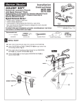
Apply a bead of putty along the edge of the underside of the FAUCET (1).
Fig. A.
Insert FAUCET (1) and CABLE CONNECTOR (2) through center hole
of mounting surface. Fig. A.
From under side of mounting surface thread the two MOUNTING
NUTS (3) onto FAUCET SHANKS (4). Fig. B.
Center FAUCET (1) and hand tighten MOUNTING NUTS (3) to
secure FAUCET (1).
1
PUTTY
3
Fig. B.
3
(HAND TIGHTEN)
2
4
1
2
INSTALL POP-UP DRAIN
Fig. A.
Remove CLEAR PLASTIC COVER (1). Remove
CARDBOARD SPACER (2) from under DRAIN
POP-UP (3). Fig. A.
REAR OF
SINK
1
4
3
Drop DRAIN BODY (4) through sink drain
hole. Make sure WHITE FOAM GASKET (5)
is under flange of DRAIN BODY (4). Fig. B.
Note: No plumber’s putty or caulk is required.
Fig. B.
6
5
SINK
DRAIN
HOLE
2
The CABLE ATTACHMENT POINT (6) must
face towards the rear of the SINK. Fig. B.
3
INSTALL BLACK GASKET
Install BLACK CONE GASKET (1) onto DRAIN BODY (2)
from below.
Note: The flat side of the BLACK CONE GASKET (1) must
face down.
2
1
FLAT SIDE OF GASKET
MUST FACE DOWN
4
INSTALL GRAY LOCKNUT
Fig. B.
Fig. A.
Install GRAY LOCKNUT (1) onto DRAIN BODY (2)
from below SINK. Fig. A.
Note: The flat side of the GRAY LOCKNUT (1)
must face up.
2
DRAIN
FLANGE
Tighten firmly by hand. No tools are required.
Check DRAIN FLANGE in SINK to ensure that
WHITE FOAM GASKET (3) is fully compressed
and not visible. Fig. B.
FLAT SIDE OF
GRAY LOCKNUT
MUST FACE UP
1
5
3
WHITE FOAM
GASKET
NOT VISIBLE
POP-UP KNOB
DOWN
POP-UP KNOB (1) must be fully down.
1
M 9 6 8 8 7 7 R e v. 1 . 2
2
6
ATTACH CABLE CONNECTOR
Fig. A.
Fig. B.
Thread CABLE CONNECTOR (1) clockwise
onto DRAIN BODY CONNECTION (2) and
hand tighten. Fig. A.
1
Your new POP-UP DRAIN installation is
now complete. Fig. B.
Note: Tailpeice on pop-up drain is 1-1/4” O.D.
Fig. B.
1-1/4” O.D.
2
7
CHECK OPERATION OF POP-UP
Operate LIFT KNOB (1) to verify that STOPPER (2) opens and
closes.
1
Note: If STOPPER (2) does not open and close properly then refer
to the “troubleshooting section” of these instructions.
2
8
MAKE WATER SUPPLY AND WASTE CONNECTIONS
NOTE: FLEXIBLE SUPPLIES OR BULL-NOSE RISERS NOT INCLUDED
AND MUST BE PURCHASED SEPARATELY.
Connect water supply to INLET SHANKS (1) with 1/2" IPS
FLEXIBLE SUPPLIES (2) or 3/8" O.D. BULL-NOSE RISERS (3).
Use adjustable wrench to tighten connections. Do not over
tighten. Be careful not to kink copper supply when bending.
Use tubing cutter to cut to proper length.
Connect HOT water supply to inlet of left SHANK and COLD
water supply to right SHANK using sealant, appropriate
connectors, and COUPLING NUTS.
Connect 1-1/4” O.D. TAILPIECE (4) on POP-UP
DRAIN to “p” trap.
3
3/8 O.D.
BULL-NOSE
RISERS
COUPLING
NUT WITH
FAUCET
1
COUPLING
NUT ON FLEX
SUPPLIES
2
COMPRESSION
NUT
FLEXIBLE
SUPPLIES
4
FERRULE
“P” TRAP
HOT
COLD
3/8 COMPRESSION
CONNECTION
M 9 6 8 8 7 7 R e v. 1 . 2
9
TEST INSTALLED FITTING
With HANDLES (1) in OFF position, turn on WATER
SUPPLIES (2) and check all connections for leaks.
5
1
Ensure that AERATOR (3) is tightened completely.
Operate HANDLES (1) to allow water flow.
3
10
CHECK DRAIN CONNECTIONS
4
Operate POP-UP KNOB (5) and fill Sink with water. Check
that DRAIN STOPPER (4) makes a good seal and retains
water in Sink. If STOPPER (4) does not seal properly, please
refer to “Troubleshooting Guide” in these instructions.
WASTE
OUTLET
Release POP-UP KNOB (5) down and check all drain
connections and "P" trap for leaks.
Tighten
if necessary.
2
2
11
“P” TRAP
SERVICE
If Faucet Drips Proceed As Follows:
Turn VALVE to OFF position.
If spout drips, operate HANDLES (1) several times from OFF to ON position. Do not force-handles they turn only 90˚.
To Change Direction Of Handle Rotation,
Proceed As Follows:
1
Turn VALVE to OFF position.
Loosen SET SCREW (2) and pull HANDLE (1) off.
Turn VALVE STEM (3) 90˚ so that flat on VALVE
STEM (3) faces away from the SPOUT (4). (Water
may turn on)
Replace HANDLE (1) and tighten SET SCREW (2).
2
4
FLAT
3
To Clean Aerator:
AERATOR (6) may accumulate dirt
causing distorted and reduced water flow.
Remove AERATOR (6) and rinse clean.
12
6
CARE INSTRUCTIONS:
DO: SIMPLY RINSE THE PRODUCT CLEAN WITH CLEAR WATER. DRY WITH A SOFT COTTON FLANNEL CLOTH.
DO NOT: DO NOT CLEAN THE PRODUCT WITH SOAPS, ACID, POLISH, ABRASIVES, HARSH CLEANERS, OR A
CLOTH WITH A COARSE SURFACE.
M 9 6 8 8 7 7 R e v. 1 . 2
4
Speed Connect™ Drain
Troubleshooting Guide
If sink does not hold water even though Stopper is in the “down” position:
• Follow CABLE ADJUSTMENT PROCEDURE.
If Stopper does not raise up fully or sink drains too slowly:
• Follow CABLE ADJUSTMENT PROCEDURE.
If you need to remove the Stopper:
• Follow STOPPER REMOVAL PROCEDURE.
If you would like the ability to remove your Stopper simply by lifting it out of the drain:
• Follow STOPPER INSTALLATION PROCEDURE for “Unlocked” mode.
CABLE ADJUSTMENT PROCEDURE
Disconnect the Cable from the Drain by threading the Cable Connector (1) counter-clockwise. Fig. A.
Look at the area on the Drain Body where the Cable was attached and locate the component labeled as
“Cam” in the illustration. Fig. B.
Use a small screwdriver to rotate the Cam in the clockwise direction as far as it will go. At this point the
Stopper should be in the UP position. Fig. B, C.
Push DOWN on the Lift-Knob to make sure it is fully down. Fig. C.
Re-attach the Cable to the Drain Body Connection (2) by threading the Cable Connector (1) clockwise onto the
Drain Body Connection (2) and hand-tighten. Fig. A.
Fig. A.
Fig. B. Fig. C.
CAM
1
1
RE-ATTACH
CAM CAP
DISCONNECT
2
STOPPER REMOVAL PROCEDURE
Disconnect the Cable from the Drain by threading the Cable Connector (1) counter-clockwise. Fig. A.
Look at the area on the Drain Body where the Cable was attached and locate the component labeled
as “Cam” and “Cam Cap” in the illustration. Fig. B.
Use fingers or small screwdriver under either side of the Cam Cap to pry it out from the Drain. Fig. D.
Remove the Cam by pulling it straight out while wiggling gently to loosen the Rubber Seal. Fig. E.
The Stopper can now be removed by lifting it out of the Drain. Fig. F.
Fig. D.
Fig. F.
Fig. E.
REMOVE
CAM
REMOVE
CAM CAP
M 9 6 8 8 7 7 R e v. 1 . 2
5
STOPPER INSTALLATION PROCEDURE
The Stopper can be installed two ways, “Locked” Mode (Stopper cannot be
removed) or “Unlock” Mode (Stopper is removable).
Locked Mode:
Look at the Plastic Loop at the bottom of the Stopper and notice
that the Loop is on one side of the Stopper. Fig. G.
To install the stopper in “Locked” mode, insert the Stopper into
the Drain so that the Plastic Loop is facing toward the rear of the
Sink and the American Standard logo is facing front. Rotate
Stopper slightly if necessary so that the Stopper slides all the
way down.Fig. G.
Fig. G.
LOGO
Re-install the Cam into the Drain, rotating the Cam if necessary
to make sure it is fully inserted. Fig. J.
LOOP TOWARD
REAR OF SINK
Re-install the Cam Cap, making sure the guide teeth are facing
outward. If the Cam Cap does not “snap” into place, then rotate
the Cam to make sure it is fully inserted. Fig. K.
DRAIN
locked Mode
Re-attach Cable. See “CABLE ADJUSTMENT PROCEDURE” in
Troubling Shooting Guide to complete installation. Stopper will be
in “Locked” mode and not be removable.
Unlocked Mode:
Look at the Plastic Loop at the bottom of the Stopper and notice
that the Loop is on one side of the Stopper. Fig. H.
To install the stopper in “Unlocked” mode, insert the Stopper into
the Drain so that the Plastic Loop is facing toward the front of the
Sink and the American Standard logo is facing rear. Rotate Stopper
slightly if necessary so that the Stopper slides all the way down.
Fig. H.
Fig. H.
LOGO
180˚
Re-install the Cam into the Drain, rotating the Cam if necessary
to make sure it is fully inserted. Fig. J.
LOOP TOWARD
FRONT OF SINK
Re-install the Cam Cap, making sure the guide teeth are facing
outward. If the Cam Cap does not “snap” into place, then rotate
the Cam to make sure it is fully inserted. Fig. K.
DRAIN
Unlocked Mode
Re-attach Cable. See “CABLE ADJUSTMENT PROCEDURE” in
“Troublingshooting Guide” to complete installation. Stopper will be
in “Unlocked” mode and removable.
Fig. J.
CAM
INSTALL CAM
Fig. K.
INSTALL
CAM CAP
M 9 6 8 8 7 7 R e v. 1 . 2
6