1
Installation
Instructions
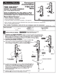
2506.101
MOMENTS
Monoblock Lavatory Faucet with
Speed Connect™ Drain
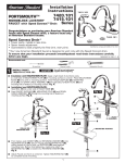
Congratulations on purchasing your American Standard
faucet with Speed Connect drain, a feature found only on
American Standard faucets.
Certified to comply with ANSI A112.18.1
Speed Connect Drain*
M968941 Rev. 1.2
• Fewer parts, installs in less time
• Never needs adjustment
• Guaranteed to seal properly the first time, every time.
*Your new American Standard faucet is designed to work only with the Speed Connect drain.
To ensure that your installation proceeds smoothly-please read these instructions carefully before you begin.
Recommended tools
Screwdriver
1
INSTALL FAUCET
CAUTION
Channel Locks
Adjustable Wrench
Turn off hot and cold water
supplies before beginning.
Seat SEAL (1) into under side of FAUCET BASE (2).
Feed FAUCET SUPPLIES (3), MOUNTING STUD (4) and DRAIN
CABLE ASSEMBLY (8) through the mounting hole of lavatory or
mounting surface. Fig. A.
From below, push GASKET (7) and RETAINING WASHER (5) onto
MOUNTING STUD (4). Secure Faucet with MOUNTING NUT (6),
pulling faucet to front of sink, so SUPPLIES (3) rests against
mounting hole. Before final tightening, make sure collar on
MOUNTING NUT (6) is seated into RETAINING WASHER (5).
Fig. B.
Adjust Faucet so that it is centered. Tighten MOUNTING NUT (6)
to complete faucet mounting.
Fig. A.
2
GROOVE
(FAUCET
BASE)
4
MOUNTING SURFACE
Fig. B.
8
COLLAR ON
MOUNTING NUT
7
5
6
4
1
1
3
2
POP-UP DRAIN
Fig. A.
Fig. B.
Remove CLEAR PLASTIC COVER (1).
1
Remove CARDBOARD SPACER (2) from under
DRAIN POP-UP (3).
3
DRAIN
BODY
Tighten TAILPIECE (4) on DRAIN BODY before
installing DRAIN BODY. Fig. B.
2
3
REMOVE FLANGE
4
Fig. A.
Thread FLANGE (1) counter-clockwise and remove
FLANGE (1) and FOAM GASKET (2) from drain
body. Fig. A.
Fig. B.
1
Thread LOCKNUT (3) clock-wise to bottom of
drain body. Push GASKET (4) down against
LOCKNUT (3). Fig. B.
4
2
3
4
INSTALL DRAIN FROM
BELOW FIXTURE
From under side of SINK
install DRAIN BODY (1) up
through drain outlet.
Note: No plumber’s putty
or caulk is required.
The CABLE ATTACHMENT
POINT (2) must face towards
the rear of the SINK.
REAR
OF SINK
4
TIGHTEN LOCKNUT
Tighten LOCKNUT (1) firmly with Adjustable
Wrench or Channel Locks.
DRAIN
OUTLET
3
FLANGE GASKET AND POP-UP KNOB
1
1
Install FOAM GASKET (3) and
FLANGE (4) onto drain body
from above SINK and tighten
FLANGE (4) firmly.
6
5
2
Fig. A.
Fig. B.
Check DRAIN FLANGE in SINK to ensure that
WHITE FOAM GASKET (3) is fully compressed
and not visible. Fig. A.
POP-UP KNOB (1) must be fully down. Fig. B.
DOWN
1
WHITE FOAM
GASKET
NOT VISIBLE
DRAIN
FLANGE
M968941 Rev. 1.2
2
7
ATTACH CABLE CONNECTOR
Fig. A.
Fig. B.
Thread CABLE CONNECTOR (1) clockwise
onto DRAIN BODY CONNECTION (2) and
hand tighten. Fig. A.
1
Your new POP-UP DRAIN installation is
now complete. Fig. B.
Note: Tailpeice on pop-up drain is 1-1/4” O.D.
Fig. B.
2
1-1/4” O.D.
8
CHECK OPERATION OF POP-UP
Operate LIFT KNOB (1) to verify that STOPPER (2) opens and
closes.
1
Note: If STOPPER (2) does not open and close properly then
refer to the “troubleshooting section” of these instructions.
2
9
MAKE WATER SUPPLY AND WASTE CONNECTIONS
Connect FLEXIBLE SUPPLIES (1, 2) directly to wall supplies.
Connection on fitting supplies are 3/8" compression. Connect
left SUPPLY (1) to Hot (Marked with a Red Band) and right supply
to COLD (2) wall supply.
1
Faucet supplies are 20" long from faucet base.
Note: If additional supply length is required, installer must
purchase additional parts separately.
Important: If SUPPLY HOSES (1, 2) are to long, loop as
illustrated to avoid kinking.
Connect 1-1/4” O.D. tailpiece on POP-UP DRAIN to
waste outlet.
APPROX. 20"
2
1
RED
BAND
BLUE
BAND
3/8" COMPRESSION
HOT
COLD
M968941 Rev. 1.2
3
10
TEST INSTALLED FITTING
ON
With HANDLE (1) in OFF position, turn on WATER
SUPPLIES (2) and check all connections for leaks.
1
OFF
COLD
Remove AERATOR (3).
HOT
Operate HANDLE (1) to flush water lines thoroughly.
4
Replace AERATOR (3).
CHECK DRAIN CONNECTIONS
Operate POP-UP KNOB (4) and fill lavatory with water.
Check that DRAIN STOPPER (5) makes a good seal
and retains water in SINK. If DRAIN STOPPER (5)
does not seal properly, please refer to Troubleshooting
section in these instructions.
3
5
Release POP-UP KNOB (4) down and check all drain
connections and "P" trap for leaks.
Tighten
if necessary.
WASTE
OUTLET
2
2
SERVICE
Turn on valve and allow water supply temperatures to
stabilize. Move HANDLE to full HOT setting. Check
water temperature.
3
Pull out Plug Button (1), loosen Handle Set Screw (2)
and remove Handle (3) from Cartridge Stem (5). Remove
Cartridge Cover (4).
Lift Setting Insert (6), rotate counterclockwise one notch
and replace. Check water temperature and repeat if
necessary. Unit is factory set at "0" (full HOT water). As
the setting number increases, the more cold water is
supplied in the full HOT handle position.
Replace Cartridge Cover (4). Align Handle (3) and tighten
Set Screw (2). Replace Plug Button (1).
12
HOTTEST
1
2
1
2
4
3
4
To decrease hot limit temperature setting:
TOP
CARTRIDGE
5
6
Blend control
setting 0 - setting
insert covers blend
control setting
number 1 - 4
TOP
6
COOLEST
1
2
3
4
11
“P” TRAP
Blend control
setting 4
CARE INSTRUCTIONS:
DO: SIMPLY RINSE THE PRODUCT CLEAN WITH CLEAR WATER. DRY WITH A SOFT COTTON FLANNEL CLOTH.
DO NOT: DO NOT CLEAN THE PRODUCT WITH SOAPS, ACID, POLISH, ABRASIVES, HARSH CLEANERS, OR A
CLOTH WITH A COARSE SURFACE.
M968941 Rev. 1.2
4
Speed Connect™ Drain
Troubleshooting Guide
If sink does not hold water even though Stopper is in the “down” position:
• Follow CABLE ADJUSTMENT PROCEDURE.
If Stopper does not raise up fully or sink drains too slowly:
• Follow CABLE ADJUSTMENT PROCEDURE.
If you need to remove the Stopper:
• Follow STOPPER REMOVAL PROCEDURE.
If you would like the ability to remove your Stopper simply by lifting it out of the drain:
• Follow STOPPER INSTALLATION PROCEDURE for “Unlocked” mode.
CABLE ADJUSTMENT PROCEDURE
Disconnect the Cable from the Drain by threading the Cable Connector (1) counter-clockwise. Fig. A.
Look at the area on the Drain Body where the Cable was attached and locate the component labeled as
“Cam” in the illustration. Fig. B.
Use a small screwdriver to rotate the Cam in the clockwise direction as far as it will go. At this point the
Stopper should be in the UP position. Fig. B, C.
Push DOWN on the Lift-Knob to make sure it is fully down. Fig. C.
Re-attach the Cable to the Drain Body Connection (2) by threading the Cable Connector (1) clockwise onto the
Drain Body Connection (2) and hand-tighten. Fig. A.
Fig. A.
Fig. B. Fig. C.
DOWN
CAM
1
RE-ATTACH
1
CAM CAP
STOPPER
DISCONNECT
2
STOPPER REMOVAL PROCEDURE
Disconnect the Cable from the Drain by threading the Cable Connector (1) counter-clockwise. Fig. A.
Look at the area on the Drain Body where the Cable was attached and locate the component labeled
as “Cam” and “Cam Cap” in the illustration. Fig. B.
Use fingers or small screwdriver under either side of the Cam Cap to pry it out from the Drain. Fig. D.
Remove the Cam by pulling it straight out while wiggling gently to loosen the Rubber Seal. Fig. E.
The Stopper can now be removed by lifting it out of the Drain. Fig. F.
Fig. D.
Fig. E.
REMOVE
CAM
Fig. F.
REMOVE
CAM CAP
M968941 Rev. 1.2
5
STOPPER INSTALLATION PROCEDURE
The Stopper can be installed two ways, “Locked” Mode (Stopper cannot be
removed) or “Unlock” Mode (Stopper is removable).
Locked Mode:
Look at the Plastic Loop at the bottom of the Stopper and notice
that the Loop is on one side of the Stopper. Fig. G.
To install the stopper in “Locked” mode, insert the Stopper into
the Drain so that the Plastic Loop is facing toward the rear of the
Sink and the American Standard logo is facing front. Rotate
Stopper slightly if necessary so that the Stopper slides all the
way down.Fig. G.
Fig. G.
LOGO
Re-install the Cam into the Drain, rotating the Cam if necessary
to make sure it is fully inserted. Fig. J.
LOOP TOWARD
REAR OF SINK
Re-install the Cam Cap, making sure the guide teeth are facing
outward. If the Cam Cap does not “snap” into place, then rotate
the Cam to make sure it is fully inserted. Fig. K.
DRAIN
Locked Mode
(Vandal Proof)
Re-attach Cable. See “CABLE ADJUSTMENT PROCEDURE” in
Troubling Shooting Guide to complete installation. Stopper will be
in “Locked” mode and not be removable.
Unlocked Mode:
Look at the Plastic Loop at the bottom of the Stopper and notice
that the Loop is on one side of the Stopper. Fig. H.
To install the stopper in “Unlocked” mode, insert the Stopper into
the Drain so that the Plastic Loop is facing toward the front of the
Sink and the American Standard logo is facing rear. Rotate Stopper
slightly if necessary so that the Stopper slides all the way down.
Fig. H.
Fig. H.
LOGO
180˚
Re-install the Cam into the Drain, rotating the Cam if necessary
to make sure it is fully inserted. Fig. J.
LOOP TOWARD
FRONT OF SINK
Re-install the Cam Cap, making sure the guide teeth are facing
outward. If the Cam Cap does not “snap” into place, then rotate
the Cam to make sure it is fully inserted. Fig. K.
DRAIN
Unlocked Mode
Re-attach Cable. See “CABLE ADJUSTMENT PROCEDURE” in
“Troublingshooting Guide” to complete installation. Stopper will be
in “Unlocked” mode and removable.
Fig. J.
CAM
INSTALL CAM
Fig. K.
INSTALL
CAM CAP
M968941 Rev. 1.2
6
MOMENTS
Momoblock Lavatory Faucet
with Pop-up Drain
M962558-YYY0A
HANDLE
MODEL NUMBERS
M962559-0070A
BUTTON AND
SCREW KIT
2.5mm HEX KEY
A906099-0070A
HANDLE ADAPTER
2506.101
M962561-YYY0A
CARTRIDGE COVER
M923320-YYY0A
CARTRIDGE NUT
A912740-0070A
O-RING
951970-0070A
CARTRIDGE
M962544-YYY0A
STOPPER
ASSEMBLY
M961619-0070A
MANIFOLD
M952430-0070A
CABLE ASSEMBLY
M952425-YYY0A
DRAIN ASSEMBLY
M962457-YYY0A
FLANGE
ASSEMBLY
M962560-YYY0A
POP-UP ROD
M922881-YYY0A
AERATOR
M922872-0070A
CAM SEAT INSERT
M962552-0070A
CAM ASSEMBLY
M913207-0070A
TAILPIECE INSERT
A911836-0070A
SEAL
M919660-0020A
6” TAILPIECE
(NOT INCLUDED
WITH FAUCET)
M962492-0070A
MOUNTING KIT
M918462-0070A
CABLE ADAPTER
A919661-0020A
TAILPIECE
M962458-0070A
DRAIN MOUNTING KIT
Replace the "YYY" with
appropriate finish code
CHROME
STAINLESS STEEL
002
075
HOT LINE FOR HELP
For toll-free information and answers to your questions, call:
1-800 442-1902
Weekdays 8:00 a.m. to 6:00 p.m. EST
IN CANADA 1-800-387-0369 (TORONTO 1-905-306-1093)
Weekdays 8:00 a.m. to 7:00 p.m. EST
IN MEXICO 01-800-839-12-00
Product names listed herein are trademarks of American Standard Inc.
© AS America, Inc. 2008
M968941 Rev. 1.2
7