Transcript
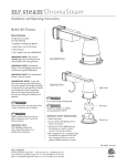
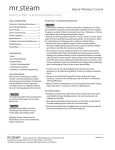
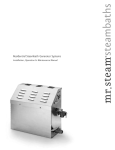
mr.steam
®
STEAM HEAD
___________________________________________________________________________________________________________________________________________
I N S TA L L AT I O N I N S T R U C T I O N S
1/8" minimum clearance required
when Acrylic Shield is used.
See installation instructions
provided with the Acrylic Shield.
Use Teflon® or equal
sealant on pipe threads
IMPORTANT: See the Installation and Operation Manual
provided with the steam generator for additional important
steamhead & control installation and operation information.
Steam
Supply Pipe
Installation: Steam Head (1⁄ 2" NPT)
!
CAUTION
INSTALLER: Because the steam head and direct steam
emissions are very hot, locate the steam head where incidental contact
by bather with the steam head or direct steam emission cannot occur.
Apply with silicone or
equal sealant as required
for moisture seal.
End of pipe to be recessed
1/4" (without Acrylic Shield)
1/8" (with Acrylic Shield)
Oil Well
STEP 1
Locate steam head 6-12 inches above floor, except for:
• Tub/shower enclosures, install 6 inches above tub top edge.
• For enclosures with acrylic or other non-heat resistant
flooring install Acrylic Shield Part Number MS-103938.
STEP 3
STEP 2
Install steamhead with the oil well facing up as shown. Hand tightening
is sufficient when teflon or equal pipe thread sealing compound is used.
IMPORTANT NOTE: to preserve steam head finish, do not use
wrench or other tools to tighten. DO NOT use abrasive cleansers or
chemicals. Use only water with mild soap and a non-abrasive sponge.
!
Drop Ear
Fitting
CAUTION
Consult with supplier of acrylic, fiberglass and other
non-heat resistant enclosures for recommended steamhead location.
Use Acrylic Shield part number MS-103938. See instructions provided
with steam shield.
STEP 4
STEP 3
Secure a bronze drop ear fitting to a header and run a 1/2" copper
steamline from the steam generator to the drop ear fitting. Install
a temporary nipple (6" or longer)in the drop ear fitting to locate
the steamhead after the wall is finished.
STEP 4
After the wall has been finished, mark on the nipple where the surface
of the wall is. Remove the nipple and measure the portion that was
in the wall (the end to your mark). Subtract 1⁄ 4" from that dimension
and select a brass nipple of that length to finish the installation.
STEP 5
STEP 5
Wrap teflon tape around the threads of the new nipple and screw
the nipple into the steamhead. Do not use wrenches or tools which
would damage the steamhead's finish. Wrap teflon tape around the
threads of the nipple and screw the nipple and steamhead assembly
you just made into the drop ear fitting in the wall. The steamhead
should be flush with the wall and the well must be facing up.
7/8”
1”
3”
Steamhead
(shown with
optional acrylic shield)
31/2”
Locating Nipple
103937
104040
(iTempo Round)
(iTempo Square)
23/4”
104104
(iSteam)
3”
All drawings are for illustrative purposes only
0 3”
mr.steam Sussman-Automatic Corp® [email protected] www.mrsteam.com
43-20 34th Street, Long Island City, NY 11101 tel: 1 800 76 STEAM fax: 718 472 3256
®
9410 S. La Cienega Blvd. Inglewood CA 90301 tel: 1 800 72 STEAM fax: 310 216 2944
PUR 100421 5.13