1
INSTALLATION PROCEDURE
Design House is a registered
brand of DHI Corp.
Mequon, WI 53092
1-800-558-8700
TWO HANDLE
LAVATORY FAUCET
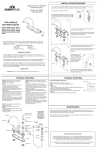
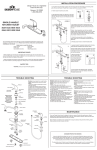
1. Shut off hot and cold water supplies under sink. Plug sink drain with cloth to avoid losing small
parts. Remove old faucet
4. Remove aerator and turn on
water. Allow both hot and cold
water to run for at least one
minute to flush system of any
debris. Turn off and replace
aerator.
2. FIT GASKET TO BOTTOM OF 3. WRAP THREADED FAUCET
FAUCET BODY BEFORE
SHANKS WITH TEFLON TAPE
INSTALLING FAUCET ON SINK. BEFORE CONNECTING
WATER LINES.
Install faucet on sink with the
C (cold) to the right and the
Insert hose up into faucet shank
H (hot) to the left. From under
and carefully tighten nut.
sink, thread wing nut to threaded
shafts. Hand tighten.
5. Check for leaks. Correct by
slightly tightening connections. IF
LEAKS PERSIST, SEE TROUBLE
SHOOTING.
H
2
C
3
H
Models 529164, 529503, 529537
527010, 527044, 527069, 527333
527390, 527432, 527457, 529156
529396, 527812, 529016, 529677
529909, 529917, 529289, 529644
529479, 527002, 526657, 526665
526673, 526681, 526855, 526921
526939, 528562
4
H
H
C
C
C
TO
HOT
TO
COLD
Your new Design House faucet will give you years of trouble free performance. Thank you for
choosing our product for your home. Please read all of these instructions carefully before
installing your new faucet.
Helpful tools to install this faucet:
basin wrench
silicon sealer
Teflon tape
flashlight
(2) crescent wrenches
faucet supply tubes
IMPORTANT POINTS
When installing your new faucet, hand tighten the connector nuts, then use one wrench to
anchor the fitting and a second wrench to tighten the nut one additional turn. Connections that are
too tight will reduce the integrity of the system.
MAINTENANCE
Your new Design House faucet is designed to give you years of trouble free performance. Keep it
looking new by cleaning it periodically with a soft cloth. Avoid abrasive cleaners, steel wool and harsh
chemicals that will dull the finish and void your warranty.
Brass finishes are polished, then protected with a lacquer coating to help prevent tarnishing. Clean
these surfaces only with a damp, soft cloth.
Wrap all threaded connections (except aerator thread in spout) with Teflon tape available from
your local hardware or plumbing supply store. Always wrap in a counter-clockwise direction.
CONSUMER PROTECTION WARNING
Under the Safe Drinking Water Act, the U.S. Environmental Protection Agency restricts the
amount of lead used in brass and solder. Your new faucet is made in strict compliance with all
government standards. The materials used in the manufacture of this faucet are of industry
standard quality and are similar to other plumbing products having brass fittings.
SAFETY TIPS
ALWAYS protect your eyes with safety glasses.
To reduce the amount of lead in your drinking water, allow the water to run for a moment before
filling your glass and remember to always use cold water for drinking purposes.
TROUBLE SHOOTING
Problem: Faucet leaks from under handle.
Cause: Retainer nut is loose or o-ring on
cartridge is dirty or twisted.
Action:
1. Move handle to OFF position. Remove the
handle by unscrewing handle screw.
2. Tighten the retainer nut by turning it
clockwise. Move the cartridge stem to the ON
position. The leak should stop around the
cartridge stem.
3. If the leak does not stop, shut off the water
supply. Remove the retainer nut by turning it
counter clockwise. Lift out the cartridge valve.
Inspect the o-rings. Clear debris, untwist, or
replace if necessary.
4. Replace the cartridge making sure the wings
fit well into the cuts in the faucet body. Tightly
screw the retainer nut onto the faucet body.
5. Reinstall the handle.
Problem: Faucet leaks around aerator or an
improper flow pattern.
Cause: Aerator incorrectly fitted or dirty.
Action:
1. Unscrew the aerator. Make sure all internal
parts are laying flat.
2. If there is debris, gently flush all parts inside.
3. Reinstall aerator.
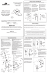
INDICATOR CAP
C
Many of these
parts come
preassembled.
This exploded
diagram is to
assist in trouble
shooting.
C
HANDLE SCREW
HANDLE
POP-UP (OPTIONAL) INSTALLATION PROCEDURE
Problem: Water does not completely shut off.
Cause: Rubber valve seat is dirty, stuck or broken.
Action:
1. Determine which side (hot, cold or both) is
leaking by shutting off the cold water supply first. If
leaking persists, the problem is on the hot side.
Shut off the hot water supply to determine if both
sides have a problem.
2. Remove the handle on the problem side.
Loosen the retainer nut and lift out the cartridge
assembly.
3. Inspect the rubber valve seat in the faucet body.
Remove any debris. If the rubber seat is stuck
tightly in the water hole, push it gently with
fingertip so that it moves up and down smoothly.
The spring (with smaller end up) must be replaced
underneath the valve seat. If the valve seat is
worn or broken, replace it.
4. Replace the cartridge making sure the wings fit
well into the cuts in the faucet body. Tightly screw
the retainer nut onto the faucet body.
5. Reinstall the handle.
LIFT ROD
CARTRIDGE
C
H
RUBBER VALVE
SEAT
SPRING
FAUCET BODY
DRAIN STOPPER
MACK WASHER
THUMB
SCREW
ROD
STRAP
PLASTIC FRICTION
WASHER
SPRING
LOCKNUT
CLIP
POP-UP DRAIN
BODY
BUSHING
PIVOT ROD
& BALL
BUSHING
PIVOT ROD
OPENING
WING NUT
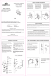
2. Insert pop-up drain body with mack
washer, plastic friction washer (not
included with plastic pop-ups) and
locknut through bottom of sink drain.
4
NONREMOVABLE
TAIL PIECE
RETAINING
NUT
3
SILICONE
SEALER
3. Apply silicone sealer to the
underside of the flange and screw it
to the top of the the pop-up drain
body. Unscrew the tail piece. Add
Teflon tape to the tail piece threads
and reattach.
TEFLON
TAPE
5
6
H
REMOVABLE
POP-UP INSTALLATION
EXPLODED PARTS
FAUCET SHANK
GASKET
2
1
C
FLANGE
RETAINER NUT
1. Remove stopper and unscrew
flange from pop-up assembly.
4. Tighten locknut, making sure the
mack washer fits into drain hole. Insert
tail piece into waste drain tube and
tighten slipnut.
5. Insert stopper into the drain opening
in a removable or non-removable
position. Place pivot bushing inside of
pivot rod opening. Place pivot rod and
ball, and second bushing into opening.
Secure with retaining nut. Do not over
tighten.
6. Insert lift rod through lift rod strap.
Tighten with thumb screw.
7. Insert pivot rod into the first spring
clip hole. Guide the pivot rod through
one of the holes in the rod strap and
secure in the second spring clip hole.
8. Adjust the height of the lift rod by
loosening the thumb screw, positioning
the lift rod, and tightly resetting the
thumb screw.
7,8
PROCEDIMIENTO DE INSTALACIÓN
Design House es una marca
registrada de DHI Corp.
Mequon, WI 53092
1-800-558-8700
GRIFO DE DOS MANGOS
PARA LAVAMANOS
H
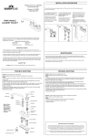
2. COLOQUE EL EMPAQUE EN LA
PARTE INFERIOR DEL ARMAZÓN
DEL GRIFO ANTES DE INSTALAR EL
GRIFO EN EL LAVAMANOS.
Instale el grifo en el lavamanos con la
C (frío) a la derecha y la H (caliente) a
la izquierda. Por debajo del
lavamanos, enrosque las tuercas de
mariposa en los vástagos del grifo.
Apriete a mano.
3. ENVUELVA LOS VÁSTAGOS
ROSCADOS DEL GRIFO CON
CINTA DE TEFLÓN ANTES DE
CONECTAR LAS LÍNEAS DE
AGUA.
Inserte la manguera hacia arriba en
el vástago del grifo y apriete
cuidadosamente la tuerca.
2
C
4. Quite el aireador y abra las llaves del
agua. Permita que tanto el agua caliente
como la fría corran durante al menos un
minuto para desaguar el sistema de
cualquier escombro. Cierre las llaves y
vuelva a colocar el aireador.
5. Revise si hay fugas. Corríjalas
apretando levemente las conexiones. SI
LAS FUGAS PERSISTEN, CONSULTE
LA RESOLUCIÓN DE PROBLEMAS.
3
H
Modelos 529164, 529503, 529537
527010, 527044, 527069, 527333
527390, 527432, 527457, 529156
529396, 527812, 529016, 529677
529909, 529917, 529289, 529644
529479, 527002, 526657, 526665
526673, 526681, 526855, 526921
526939, 528562
1. Desconecte el suministro del agua caliente y fría bajo el fregadero. Tape el drenaje con un trapo para evitar perder
partes pequeñas. Quite el grifo viejo.
4
H
H
C
C
C
TO
HOT
Su nuevo grifo de Design House le dará años de funcionamiento sin problemas. Gracias por
escoger nuestro producto para su hogar. Por favor lea todas estas instrucciones con cuidado
antes de instalar su nuevo grifo.
Herramientas útiles para instalar este grifo:
Llave para lavabo
Sellador de silicona
Cinta de teflón
Linterna
Dos (2) llaves
Tubos de suministro para grifo
PUNTOS IMPORTANTES
Cuando instale su nuevo grifo, apriete a mano las tuercas de conector, luego use una llave para
anclar el conector y otra para apretar la tuerca una vuelta más. Las conexiones que estén
demasiado apretadas reducirán la integridad del sistema.
TO
COLD
MANTENIMIENTO
Su nuevo grifo de Design House está diseñado para darle años de funcionamiento sin problemas.
Manténgalo viéndose como nuevo limpiándolo periódicamente con un paño suave. Evite usar
limpiadores abrasivos, lana de acero y químicos fuertes que opacarán el acabado y anularán la
garantía.
Los acabados en latón están pulidos y luego protegidos con una capa de laca para ayudar a prevenir
su pérdida de lustre. Limpie estas superficies solamente con un paño húmedo y suave.
Envuelva todas las conexiones roscadas (salvo la rosca del aireador en la boquilla) con cinta de
teflón - disponible en su ferretería local o en la tienda de suministros de plomería. Envuelva
siempre en dirección opuesta a la de las manecillas del reloj.
GARANTÍA DE PROTECCIÓN DEL CONSUMIDOR
Bajo la Ley de Agua Potable Segura, la Agencia de Protección Ambiental de Estados Unidos
restringe la cantidad de plomo usado en el latón y la soldadura. Su nuevo grifo está hecho
cumpliendo estrictamente con todos los estándares gubernamentales.
Los materiales usados en la fabricación de este grifo son de calidad con estándar industrial y son
similares a otros productos de plomería que tienen conectores de latón.
CONSEJOS DE SEGURIDAD
Proteja SIEMPRE sus ojos con gafas de seguridad.
Para reducir la cantidad de plomo en su agua potable, permita que el agua corra por un momento
antes de llenar su vaso y recuerde siempre usar agua fría para tomar.
RESOLUCIÓN DE PROBLEMAS.
Problema: el grifo gotea bajo el mango.
Causa: está floja la tuerca de retención o la junta tórica
del cartucho está sucia o retorcida.
Acción:
1. Mueva el mango a la posición de apagado (OFF).
Quite el mango destornillando el tornillo.
2. Apriete la tuerca de retención girándola en sentido
de las manecillas del reloj. Mueva el tallo del cartucho
a la posición de encendido (ON). El goteo alrededor
del tallo del cartucho debería detenerse.
3. Si el goteo no se detiene, desconecte el suministro
de agua. Quite la tuerca de retención girándola en
sentido contrario a las manecillas del reloj. Levante la
válvula del cartucho. Inspeccione las juntas tóricas.
Límpieles los escombros, enderécelas o reemplácelas
de ser necesario.
4. Vuelva a colocar el cartucho asegurándose de que
las alas quepan bien dentro de los cortes en el
armazón del grifo. Enrosque firmemente la tuerca de
retención en el armazón del grifo.
5. Reinstale el mango.
C
Problema: el grifo gotea alrededor del aireador o tiene un
flujo de agua incorrecto.
Causa: el aireador está sucio o inadecuadamente
colocado.
Acción:
1. Destornille el aireador. Asegúrese de que todas las
partes internas estén colocadas de forma horizontal.
2. Si hay escombros, lave con cuidado todas las partes
internas.
3. Reinstale el aireador.
TAPA CON INDICADOR
Muchas de estas
TORNILLO DEL MANGO
partes
ya vienen
MANGO
C
preensambladas.
Este diagrama
expandido
es para ayudarle
TUERCA DE RETENCIÓN
en la resolución
de problemas.
VARILLA
DE ELEVACIÓN
CARTUCHO
C
H
ASIENTO DE HULE
DE LA VÁLVULA
RESORTE
ARMAZÓN DEL GRIFO
VÁSTAGO DEL GRIFO
EMPAQUE
PROCEDIMIENTO DE INSTALACIÓN CON EL DESAGÜE LEVADIZO (OPCIONAL)
Problema: : el chorro no se cierra completamente.
Causa: el asiento de hule de la válvula está sucio,
trabado o roto.
Acción:
1. Determine qué lado (caliente, frío o ambos) está
goteando desconectando el suministro de agua fría
primero. Si el goteo persiste, el problema está del lado
caliente. Desconecte el suministro de agua caliente para
determinar si ambos lados cuentan con un problema.
2. Quite el mango del lado con el problema. Afloje la
tuerca de retención y saque el ensamblaje del cartucho.
3. Inspeccione el asiento de hule de la válvula en el
armazón del grifo. Quite cualquier escombro. Si el asiento
de hule está trabado firmemente en el agujero del agua,
empújelo suavemente con la punta del dedo para que se
pueda mover hacia arriba y hacia abajo sin problemas. El
resorte (con el lado pequeño hacia arriba) debe volverse
a colocar debajo del asiento de la válvula. Si el asiento de
la válvula está gastado o roto, reemplácelo.
4. Vuelva a colocar el cartucho asegurándose de que las
alas quepan bien dentro de los cortes en el armazón del
grifo. Enrosque firmemente la tuerca de retención en el
armazón del grifo.
5. Reinstale el mango.
TAPÓN DEL DESAGÜE
BRIDA
TORNILLO
DE MANO
ARANDELA HELICOIDAL
TIRA DE LA VARILLA
ARANDELA
PLÁSTICA DE FRICCIÓN
PRENSA
CONTRATUERCA
DE
RESORTE
ARMAZÓN
DEL DESAGÜE
LEVADIZO
BUJE
TUERCA
DE RETENCIÓN
VARILLA DE PIVOTE
CON BOLA
BUJE
PIEZA DE EXTREMO
2
1
2. Inserte el armazón del desagüe
levadizo con la arandela helicoidal,
arandela plástica de fricción (no
incluida con los levadizos de plástico)
y contratuerca a través de la parte
inferior del desagüe del lavamanos.
4
NONREMOVABLE
Cinta
de teflón
5
6
H
REMOVABLE
C
7. Inserte la varilla de pivote en el
primer agujero de la abrazadera de
resorte. Pase la varilla de pivote a
través de uno de los agujeros de la
tira de la varilla y asegúrela en el
segundo agujero de la abrazadera de
resorte.
8. Ajuste la altura de la varilla de
elevación aflojando el tornillo de mano,
posicionando la varilla de elevación y
reajustando firmemente el tornillo de
mano.
3
Sellador
de silicona
3. Aplique sellador de silicona a la
parte inferior de la brida y enrósquela
en la parte superior del armazón del
desagüe levadizo. Desenrosque la
pieza de extremo. Agregue cinta de
teflón a la rosca de la pieza de
extremo y vuelva a acoplarla.
INSTALACIÓN CON
DESAGÜE LEVADIZO
PARTES EXPANDIDAS
ABERTURA DE LA VARILLA DE PIVOTE
TUERCA DE MARIPOSA
1. Quite el tapón y desenrosque la
brida del ensamblaje levadizo.
4. Apriete la contratuerca
asegurándose de que la arandela
helicoidal quepa en el agujero del
desagüe. Inserte la pieza de extremo
en el tubo de desagüe y apriete la
tuerca deslizante.
5. Inserte el tapón en la abertura del
desagüe en una posición en la que se
pueda quitar o no. Coloque el buje de
pivote dentro de la abertura de la
varilla de pivote. Coloque la varilla
de pivote con bola y el segundo buje
dentro de la abertura. Asegure con la
tuerca de retención. No apriete en
exceso.
6. Inserte la varilla de elevación a
través de la tira de la varilla. Apriete
con el tornillo de mano.
7,8