1
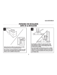
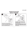
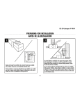
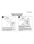
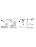
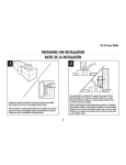
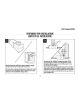
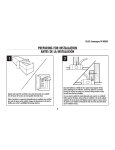
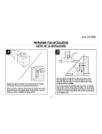
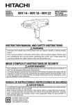
ETL-ES-Petite-WH14
PREPARING FOR INSTALLATION
ANTES DE LA INSTALACIÓN
1
2
Unpack and inspect fan carefully to be certain all contents are included.
Turn off power at fuse box to avoid possible electrical shock.
Use metal outlet box suitable for fan support (must support 35 lbs).
Before attaching fan to outlet box, ensure the outlet box is securely
fastened by at least two points to a structural ceiling member (a loose
box will cause the fan to wobble).
Use una caja de embutir de metal adecuada para soportar un ventilador
(debe soportar 35 libras). Antes de fijar el ventilador a la caja de embutir
asegúrese de que la misma esté fijada de manera segura en por lo menos
dos puntos a un miembro estructural del cielo raso (una caja suelta haría
que el ventilador oscile).
Quite el envoltorio e inspeccione detenidamente el ventilador para verificar
que todas las piezas estén incluidas. Apague la alimentación en la caja de
fusibles para evitar la posibilidad de descarga eléctrica.
5
ETL-ES-Petite-WH14
MOUNTING BRACKET INSTALLATION
INSTALACIÓN CON SOPORTE DE MONTAJE
2
3
2
4
1
1
Remove the screws and star washers (1) from the bracket as shown above.
Loosen (do not remove) the screws (2) from the bracket as shown above.
Install mounting bracket to outlet box in ceiling using the screws and washers
provided with the outlet box.
Remove screws from motor bracket and mounting plate. Hang fan from
mounting plate by inserting "T"-shaped end of bracket into slot opening of
mounting plate. This will allow for hands free wiring.
Quite los tornillos y las arandelas en estrella (1) del soporte como se indica más arriba.
Afloje (no quite) los tornillos (2) del soporte como se indica más arriba.
Instale el soporte de montaje a la caja de embutir del cielorraso con la tornillería
suministrada con la caja de embutir.
Extraiga los tornillos del soporte del motor y de la placa de montaje.
Cuelgue el ventilador de la placa de montaje insertando el extremo del
soporte con forma de “T” adentro de la ranura de la placa de montaje. De
este modo, tendrá las dos manos libres para hacer el cableado.
6
ETL-ES-Petite-WH14
MOUNTING
MONTAJE
5
While fan is hanging from the mounting plate, connect the wires with wire connectors (included), using the following steps
for wiring options.
Mientras el ventilador está colgado de la placa de montaje, conecte los cables con los conectores para cables (incluidos)
usando los siguientes pasos para opciones de cableado.
7
ETL-ES-Petite-WH14
WIRING OPTIONS
OPCIÓN DE CABLEADO
6
PULL CHAIN WIRING OPTION
WALL CONTROL WIRING OPTION
7
Follow diagram above to make wiring connections for fan pull chain control.
Follow diagram above to make wiring connections for wall control operation.
OPCIÓN DE CABLEADO PARA CONTROL DE PARED
OPCIÓN DE CABLEADO PARA CADENILLA DE TIRO
Del Ventilador:
Blanco (común)
Negro (vivo)
Azul* (vivo)
Principal (tierra)
(conectar)
(conectar)
(conectar)
(conectar)
De La Casa:
Blanco (común)
Interruptor del ventilador (vivo)
Interruptor de la luz (vivo)
Verde (de tierra)
Control de pared
*Conecte el cable azul sólo si conecta un juego de luces al ventilador.
Siga las instrucciones del diagrama anterior para hacer las conexiones de
cableado para el ventilador con control de pared.
Siga las instrucciones del diagrama anterior para hacer las conexiones de
cableado para el ventilador controlado con cadenilla de tiro.
8
ETL-ES-Petite-WH14
MOUNTING
MONTAJE
8
3
1
9
10
1
2
2
The decorative motor housing has two mating slots (1) and two
mating holes (2). Position both slots on the motor housing directly
under and in line with two screws in the mounting bracket (3).
Lift the motor housing, allowing the two screws to slide into the
mating slots. Rotate the motor housing clockwise until both screws
from the mounting bracket drop into the slot recesses. Tighten
screws securely.
Push motor upward and attach the motor to
the mounting plate by tightly securing with
screws and washers provided.
Empuje el motor hacia arriba y fije el motor
a la placa de montaje asegurando firmemente
con los tornillos y las arandelas incluidos.
El alojamiento decorativo del motor tiene dos ranuras coincidentes
(1) y dos orificios coincidentes (2). Coloque ambas ranuras del
alojamiento del motor directamente abajo y en línea con los dos
tornillos del soporte de montaje (3). Eleve el alojamiento del
motor, permitiendo que los dos tornillos se deslicen dentro de las
ranuras. Gire el alojamiento del motor en sentido horario hasta
que ambos tornillos del soporte de montaje caigan adentro de las
ranuras. Apriete los tornillos asegurándolos.
9
Install two screws and star washers into the mating holes
of the motor housing and tighten to secure the housing to
the mounting bracket.
Instale los dos tornillos y las arandelas en estrella en
los orificios coincidentes del alojamiento del motor y
ajústelos para asegurar el alojamiento al soporte de
montaje.
ETL-ES-Petite-WH14
BLADE INSTALLATION
INSTALACIÓN DE LAS PALETAS
12
11
2
2
1
Check the motor for plastic shipping stabilizer tabs (1), and remove
them if they are present. Attach blade assembly to motor using the
noise-dampening motor gaskets (2) and motor screws provided. Tighten
screws ecurely. NOTE: Some models do not utilize motor gaskets,
washers, or stabilizer tabs.
Attach blade brackets to blades using the blade bracket screws (1),
metal washers (2), and fabric washers (3), if provided. NOTE: Some
models do not utilize fabric washers (3).
Verifique si hay lengüetas plásticas de embalaje para sostener al motor
(1) y descártelas. Fije el conjunto de las paletas al motor usando las juntas
reductoras de sonido del motor (2) y los tornillos para el motor incluidos.
Apriete los tornillos asegurándolos. NOTA: Algunos modelos no utilizan
juntas para el motor, arandelas o lengüetas de embalaje.
Fije los soportes para paletas a las paletas con los tornillos (1), las
arandelas de metal (2) y las de tela (3), si corresponde.
NOTA: Algunos modelos no utilizan arandelas de tela (3).
10
ETL-ES-Petite-WH14
LIGHT FIXTURE INSTALLATION
INSTALACIÓN DEL ARTEFACTO LUMINOSO
13
Find the two wires from the switch housing with the tag
that says FOR LIGHT. Connect the blue wire from the
switch housing to the black wire from the light kit, and
connect the white wire from the switch housing to the
white wire from the light kit with wire nuts provided.
Attach light kit to the switch housing using three small
screws provided.
Identifique los dos cables en la tapa del alojamiento
del interruptor rotulada “FOR LIGHT” (para las luces).
Conecte el cable azul del alojamiento del interruptor
al cable negro del artefacto luminoso y el cable blanco
del alojamiento del interruptor al cable blanco del
artefacto luminoso usando las tuercas para cables
incluidas. Conecte el artefacto luminoso al alojamiento
del interruptor con los tres tornillos pequeños incluidos.
14
15
Install light bulbs (not included).
Instale las bombillas de luz (no incluidas).
Install glass shade and finger-tighten screws as shown.
Do not overtighten screws.
Instale la pantalla de vidrio y apriete a mano los
tornillos, como se muestra. No apriete demasiado los
tornillos.
11
ETL-ES-Petite-WH14
15
Assemble decorative fob and extension chains from hardware bag to fan pull chains by inserting end
of chain into chain coupling. Confirm chains are held by lightly pulling both chains in coupling.
Sujetar las cadenas largas de tiro con las piezas finales correspondientes, a las cadenas del ventilador,
introduciendo el extremo de la cadena larga en la pieza de unión. Asegúrese de que las cadenas
están bien sujetas, tirando ligeramente de ambas cadenas en la pieza de unión.
12