1
UL-ES-Elite-WH11
PREPARING FOR INSTALLATION
ANTES DE LA INSTALACIÓN
1
2
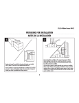
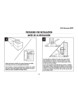
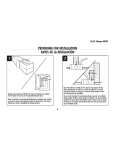
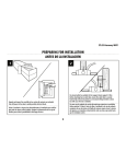
Unpack and inspect fan carefully to be certain all contents are included.
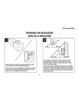
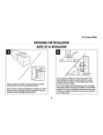
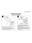
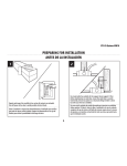
Turn off power at fuse box to avoid possible electrical shock.
Use metal outlet box suitable for fan support (must support 35 lbs).
Before attaching fan to outlet box, ensure the outlet box is securely
fastened by at least two points to a structural ceiling member (a loose
box will cause the fan to wobble).
Use una caja de embutir de metal adecuada para soportar un ventilador
(debe soportar 35 libras). Antes de fijar el ventilador a la caja de embutir
asegúrese de que la misma esté fijada de manera segura en por lo menos
dos puntos a un miembro estructural del cielo raso (una caja suelta haría
que el ventilador oscile).
Quite el envoltorio e inspeccione detenidamente el ventilador para verificar
que todas las piezas estén incluidas. Apague la alimentación en la caja de
fusibles para evitar la posibilidad de descarga eléctrica.
5
UL-ES-Elite-WH11
MOUNTING BRACKET INSTALLATION
INSTALACIÓN CON SOPORTE DE MONTAJE
3
2
1
1
2
Remove the screws and star washers from the two mating holes (1) on the canopy. Loosen (do not remove) the screws in the mating slots (2) on the canopy.
Rotate the mounting bracket counter-clockwise and remove from the canopy.
6 (no quite) los tornillos de las ranuras coincidentes (2) del dosel.
Quite los tornillos y las dos arandelas en estrella de los dos orificios coincidentes (1) del dosel. Afloje
Gire el soporte de montaje en sentido contrario a las agujas del reloj y extráigalo del dosel.
6
UL-ES-Elite-WH11
MOUNTING BRACKET INSTALLATION
INSTALACIÓN CON SOPORTE
DE MONTAJE
MOUNTING OPTIONS
OPCIONES DE MONTAJE
5
4
Choose a MOUNTING OPTION
Elija una OPCIÓN DE MONTAJE
FLUSH MOUNT OPTION
If flush mount option is selected, proceed to page 8, step 6.
OPCIÓN DE INSTALACIÓN AL RAS
Si elige la opción de montaje al ras,
proceda a la página 8, paso 6.
1
NORMAL DOWNROD OPTION
If installing downrod supplied with fan, proceed to page 9, step 8.
OPCIÓN CON VARILLA VERTICAL PARA CIELORRASO NORMAL
Si instala la varilla vertical incluida con el ventilador,
proceda a la página 9, paso 8.
EXTENDED DOWNROD OPTION
If installing with longer downrod than supplied with fan, proceed to page 9, step 9.
OPCIÓN CON VARILLA VERTICAL MÁS LARGA
Si instala una varilla vertical más larga que la que se incluye con el
ventilador, proceda a la página 9, paso 9.
Install mounting bracket (1) to outlet box in ceiling using the screws and
washers provided with the outlet box.
Instale el soporte de montaje (1) a la caja eléctrica del techo usando los tornillos
y arandelas suministrados con la caja eléctrica.
7
UL-ES-Elite-WH11
FLUSH MOUNT OPTION
OPCIÓN DE INSTALACIÓN AL RAS
7
6
For flush mount option, raise fan assembly and place onto hook from mounting
bracket into a closed hole on the canopy. This will allow for hands free wiring.
PROCEED DIRECTLY TO PAGE 13, STEP 15 FOR WIRING OPTIONS.
Para la opción de montaje al ras, levante el montaje del ventilador, colóquelo sobre
el gancho de la placa de montaje y cuélguelo en uno de los agujeros cerrados del
dosel. De este modo, tendrá las dos manos libres para hacer el cableado.
PARA LAS OPCIONES DE CABLEADO, PROCEDA DIRECTAMENTE AL PASO
13 DE LA PAGINA 15.
Guide motor wires through the base of the canopy as shown and attach canopy
directly to top of motor housing with flush mount screws and lock washers
provided. Tighten screws securely.
Deslice los cables del motor a través de la base del dosel como se indica y fije el
dosel directamente sobre el alojamiento del motor con los tornillos de montaje al
ras y las arandelas de presión incluidas. Apriete los tornillos asegurándolos.
8
UL-ES-Elite-WH11
NORMAL DOWNROD OPTION
OPCIÓN CON VARILLA VERTICAL
PARA CIELORRASO NORMAL
EXTENDED DOWNROD OPTION
OPCIÓN CON VARILLA
VERTICAL MÁS LARGA
9
3
8
2
3
1
1
Feed motor lead wires through downrod/canopy assembly and insert downrod into downrod yoke.
Make sure to align hole in downrod with the hole in downrod yoke. Install yoke cross pin (1)
through yoke and downrod. Insert clamp pin (2) into cross pin until it snaps into place. Tighten set
screws (3) in yoke. PROCEED TO PAGE 12, STEP 13.
Pase los hilos conductores del motor a través de la varilla vertical/conjunto del dosel e inserte la
varilla vertical en la horquilla de la misma. Asegúrese de que el orificio de la varilla vertical y el de
la horquilla de la varilla vertical estén alineados. Instale el pasador transversal de la horquilla (1)
pasándolo por la horquilla y la varilla vertical. Inserte el pasador de fijación (2) en el pasador
transversal hasta que escuche un chasquido que indique que está en la posición adecuada. Ajuste los
tornillos de fijación (3) en la horquilla. PROCEDA A LA PÁG. 12, PASO 13.
9
2
Loosen downrod ball (1) from downrod (2) by removing set screw (3).
Afloje la esfera de la varilla vertical (1) de la varilla vertical (2) quitando el
tornillo (3).
UL-ES-Elite-WH11
EXTENDED DOWNROD OPTION
OPCIÓN CON VARILLA VERTICAL MÁS LARGA
10
11
2
1
Slide downrod ball (1) off of downrod and remove pin (2).
Deslice la esfera de la varilla vertical (1) hasta separarla de la
varilla vertical y quite el pasador (2).
Re-install pin into extended downrod, and slide downrod ball up to the top of the downrod. Re-install
set screw to secure ball to downrod. Note: Some extended downrods have a pre-drilled set-screw hole.
If a pre-drilled hole is present in the extended downrod, tighten the set screw into the pre-drilled hole
in the extended downrod. If no pre-drilled hole exists in the extended downrod, tighten the set screw
against the downrod to secure the downrod ball.
Vuelva a instalar el pasador en la varilla vertical más larga y deslice la esfera de la varilla hasta el
extremo superior de la misma. Vuelva a insertar el tornillo de fijación para asegurar la esfera a la
varilla vertical. Nota: Algunas varillas verticales más largas tienen un agujero previamente perforado
para el tornillo. Si la varilla vertical más larga tiene un agujero previamente perforado, ajuste el
tornillo en el agujero previamente perforado de la varilla vertical más larga. Si la varilla vertical
más larga no tiene un agujero previamente perforado, ajuste el tornillo sobre la varilla vertical para
asegurar la esfera de la misma.
10
UL-ES-Elite-WH11
EXTENDED DOWNROD OPTION
OPCIÓN CON VARILLA VERTICAL MÁS LARGA
12
2
3
1
Feed motor lead wires through downrod/canopy assembly and insert downrod into downrod yoke. Make sure to align hole in downrod with the hole in downrod yoke.
Install yoke cross pin (1) through yoke and downrod. Insert clamp pin (2) into cross pin until it snaps into place. Tighten set screws (3) in yoke.
Pase los hilos conductores del motor a través de la varilla vertical/conjunto del dosel e inserte la varilla vertical en la horquilla de la misma. Asegúrese de que el orificio
de la varilla vertical y el de la horquilla de la varilla vertical estén alineados. Instale el pasador transversal de la horquilla (1) pasándolo por la horquilla y la varilla
vertical. Inserte el pasador de fijación (2) en el pasador transversal hasta que escuche un chasquido que indique que está en la posición adecuada. Ajuste los
tornillos de fijación (3) en la horquilla.
11
UL-ES-Elite-WH11
MOUNTING
MONTAJE
13
14
Carefully lift fan assembly onto mounting bracket. Rotate fan until notch
on downrod ball (1) engages the ridge on the mounting bracket (2). This
will allow for hands free wiring.
Levante con cuidado el conjunto del ventilador hasta el soporte de montaje.
Gire el ventilador hasta que la muesca de la bola de la varilla vertical (1)
calce sobre la saliente del soporte de montaje (2). De este modo, tendrá las
dos manos libres para hacer el cableado.
With bracket holding fan assembly, make electrical connections using the
following step for wiring instructions.
Con la pieza de montaje sujetando el conjunto del ventilador, haga las
conexiones eléctricas de acuerdo a las siguientes instrucciones de cableado.
12
UL-ES-Elite-WH11
WIRING OPTIONS
OPCIÓN DE CABLEADO
15
PULL CHAIN WIRING OPTION
16
Follow diagram above to make wiring connections for fan pull chain control.
WALL CONTROL WIRING OPTION
Follow diagram above to make wiring connections for wall control operation.
OPCIÓN DE CABLEADO PARA CONTROL DE PARED
OPCIÓN DE CABLEADO PARA CADENILLA DE TIRO
Siga las instrucciones del diagrama anterior para hacer las conexiones de
cableado para el ventilador con control de pared.
Siga las instrucciones del diagrama anterior para hacer las conexiones de
cableado para el ventilador controlado con cadenilla de tiro.
13
UL-ES-Elite-WH11
SECURE TO CEILING
ASEGURE EL VENTILADOR AL CIELORRASO
17
For flush mount fans, carefully lift fan from the mounting bracket, making sure not to break any wire connections.
For downrod fans, slide the canopy up to the mounting bracket.
Para ventiladores de instalación al ras, levante con cuidado el ventilador del soporte de montaje asegurándose de que no interrumpa ninguna conexión de los cables.
Para ventiladores con varilla vertical, deslice el dosel hacia arriba hasta el soporte de montaje.
3
2
1
The canopy has two mating slots (1) and two mating holes (2). Position both slots on canopy directly under and in line with two screws in the mounting bracket (3). Lift
the canopy, allowing the two screws and star wahers to slide into the mating slots. Rotate the canopy clockwise until both screws from the mounting bracket drop into the
slot recesses. Tighten screws securely. Install two screws and star washers into the mating holes of the canopy and tighten to secure the canopy to the mounting bracket.
El dosel tiene dos ranuras coincidentes (1) y dos orificios coincidentes (2). Coloque ambas ranuras del dosel directamente abajo y en línea con los dos tornillos del soporte
de montaje (3). Eleve el dosel, permitiendo que los dos tornillos y las arandelas en estrella se deslicen dentro de las ranuras. Gire el dosel en sentido horario hasta que
ambos tornillos del soporte de montaje caigan adentro de las ranuras. Apriete los tornillos asegurándolos. Instale los dos tornillos y las arandelas en estrella en los orificios
coincidentes del dosel y ajústelos para asegurar el dosel al soporte de montaje.
14
UL-ES-Elite-WH11
BLADE INSTALLATION
INSTALACIÓN DE LAS PALETAS
19
18
1
1
2
3
2
4
5
Insert the blade bracket screws (2) and fiber washers (3) into the blade bracket
(1), through the blade (4) and into the blade plate (5). Tighten all
screws securely. Repeat for all blade assemblies.
Inserte los tornillos de la abrazadera del aspa (2) y las arandelas de fibra (3) en la
abrazadera del aspa (1), atravesando el aspa (4) hasta penetrar en la placa para
aspa (5). Apriete todos los tornillos firmemente. Repita esto para todas las aspas.
Check the motor for plastic shipping stabilizer tabs and remove them if they are present.
Attach blade assembly to motor using the noise-dampening motor gaskets (1) and motor
screws (2) provided. Tighten screws securely.
NOTE: Some models do not utilize motor gaskets, washers, or stabilizer tabs.
Revise el motor por si tiene lengüetas estabilizadoras para el embalaje y retírelas si las
tuviera. Fije el conjunto de aspa al motor usando los empaques de amortiguación de ruido
para el motor (1) y los tornillos del motor (2) que se incluyen. Apriete
los tornillos firmemente.
NOTA: Algunos modelos no usan empaques de motor, arandelas o lengüetas estabilizadoras.
15
UL-ES-Elite-WH11
LIGHT FIXTURE INSTALLATION
INSTALACIÓN DEL ARTEFACTO LUMINOSO
20
21
1
2
Remove the screws (1) from the light kit (2). Find the two wires from the switch
housing with the tag that says FOR LIGHT. Connect the blue wire from the switch
housing to the black wire from the light kit, and connect the white wire from the
switch housing to the white wire from the light kit with wire nuts provided.
Retire los tornillos (1) de la tapa del juego de luces (2). Identifique los dos cables
en la tapa del alojamiento del interruptor rotulada “FOR LIGHT” (para las luces).
Conecte el cable azul del alojamiento del interruptor al cable negro del artefacto
luminoso y el cable blanco del alojamiento del interruptor al cable blanco del
artefacto luminoso usando las tuercas para cables incluidas.
Attach light kit to the switch housing using three small screws and star washers provided.
Removed in step 20.
WARNING: When lifting light kit into place, the cut out notch in light kit should be lined up
with reverse switch location when installing light kit, or damage to light kit, wiring or reverse
switch can occur.
Conecte el artefacto luminoso al alojamiento del interruptor con los tres tornillos pequeños y
las arandelas en estrella incluidos. Que retiró en el paso 20.
ADVERTENCIA: Al momento de colocar la lámpara en su sitio, la ranura en la lámpara debe
estar alineada con la ubicación del interruptor de reversa al instalar la lámpara, de lo contrario
se puede dañar la lámpara, el cableado o el interruptor de reversa. Vea a continuación.
16
UL-ES-Elite-WH11
22
23
1
Remove the spot head cover ring by twisting counterclockwise. Install GU10 light bulbs
(1), 50 watts maximum. (included)
WARNING: 1. Do not allow spot light heads to face each other.
2. All spot lights need to keep a distance of at least 4 in. between spot heads.
Retire el aro de la cubierta de la cabeza del reflector girándolo en el sentido contrario al
reloj. Instale bombillas GU10 (1) de 50 vatios como máximo.
ADVERTENCIA: 1. No permita que las cabezas de luces apunten una hacia otra.
2. Todos los reflectores necesitan una distancia mínima de 10 cm entre sí.
Re-install the spot head cover ring by twisting clockwise.
Re-instale el aro de la cubierta del reflector girándolo en el sentido del reloj.
17
UL-ES-Elite-WH11
24
Assemble decorative fob and extension chains from hardware bag to fan pull chains by
inserting end of chain into chain coupling. Confirm chains are held by lightly pulling both
chains in coupling.
Sujetar las cadenas largas de tiro con las piezas finales correspondientes, a las cadenas del
ventilador, introduciendo el extremo de la cadena larga en la pieza de unión. Asegúrese de
que las cadenas están bien sujetas, tirando ligeramente de ambas cadenas en la pieza de
unión.
18