1
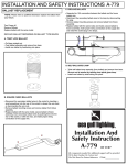
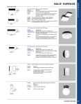
FLUORESCENT FLUSH MOUNT FIXTURE
ASSEMBLY & INSTALLATION INSTRUCTIONS
Please read carefully and save these instructions, as you may need them at a later date.
CAUTION
Turn off the main power at the circuit breaker before installing the fixture, in order to prevent possible shock.
GENERAL
All electrical connections must be in accordance with local and national electrical code (N.E.C) standards. If you
are unfamiliar with proper electrical wiring connections obtain the services of a qualified electrician.
1.
OUTLET BOX
Remove the fixture and the mounting package from the box and make sure that no parts are missing by referencing
2.
HOUSE GROUND WIRE
the illustrations on the installation instruction.
3.
FIXTURE GROUND WIRE
4.
WHITE SUPPLY WIRE
5.
WHITE FIXTURE WIRE
three CLIPS (9) outward.
6.
BLACK SUPPLY WIRE
Remove the lamps out from the LAMP BRACKETS (12) by pulling each LAMP BRACKET (12)
7.
WIRE CONNECTOR
CONNECTORS (16)&(17).
8.
BLACK FIXTURE WIRE
4.
Pull the SUPPLY WIRES (4 )&(6) and HOUSE GROUND WIRE (2) out from the OUTLET BOX (1).
9.
CLIP
5.
Make the wiring corrections: connect the HOUSE GROUND WIRE (2) to the FIXTURE GROUND WIRE
ASSEMBLY AND INSTALLATION
1.
Turn off the power.
2.
Remove the WOOD FRAME (19) with ACRYLIC LENS (18) from the FIXTURE PAN (11) by turning the
3.
backwards. Then remove the 22/32 W BALLAST RECEPTACLES (13)&(14) from the LAMP
(3); connect the WHITE SUPPLY WIRE (4) to the WHITE FIXTURE WIRE (5); connect BLACK
10. ELECTRONIC BALLAST
SUPPLY WIRE (6) to the BLACK FIXTURE WIRE (8) using WIRE CONNECTORS (7). Thread one of
11. FIXTURE PAN
the MOUNTING SCREWS (15) two full turns into the threaded hole on the OUTLET BOX (1). Carefully
tuck all wires back into the OUTLET BOX (1).
6.
Locate the FIXTURE PAN (11) over the OUTLET BOX (1), positioning the MOUNTING SCREW (15)
12. LAMP BRACKET
13. BALLAST RECEPTACLE
through the large opening of the key hole slot and then twist to the narrow opening of the key hole slot. Feed
the other MOUNTING SCREW (15) through the long hole slot on the fixture pan and thread it into the
14. BALLAST RECEPTACLE
threaded hole on the OUTLET BOX (1). Then secure the FIXTURE PAN (11) to the OUTLET BOX (1) by
15. MOUNTING SCREW
tightening the two MOUNTING SCREWS (15).
7.
Note: Both ballasts leads are rated for use with both 32 W and 22 W Circline lamps, and each ballast
16. 22 W LAMP CONNECTOR
lead can be attached to either lamp provided with the fixture. Attach one BALLAST RECEPTACLE (13)
17. 32 W LAMP CONNECTOR
to the 22 W LAMP CONNECTOR (16). Attach the 22 W CIRCLINE LAMP (20) to FIXTURE PAN (11) by
8.
9.
pulling a LAMP BRACKET (12) backward and inserting the 22 W CIRCLINE LAMP (20). (Fig. 2) Pull
18. ACRYLIC LENS
back the remaining LAMP BRACKETS (12) and insert the 22 W CIRCLINE LAMP (20).
19. WOOD FRAME
Attach the 32 W CIRCLINE LAMP (21) to the fixture, by repeating Step 7 using the remaining BALLAST
RECEPTACLE (14).
20. 22 W CIRCLINE LAMP
Secure the WOOD FRAME (19) with the ACRYLIC LENS (18) to the FIXTURE PAN (11) by turning the
21. 32 W CIRCLINE LAMP
three CLIPS (9) inward.
INSTALLATION IS NOW COMPLETED
LAMPARA FLUORESCENTE PARA TECHO INSTRUCCIONES
DE MONTAJE E INSTALACION
Por favor, lea cuidadosamente y guarde estas instrucciones, ya que puede necesitarlas posteriormente.
PRECAUCION
Desactive la electricidad del cortacircuitos antes de empezar la instalación de la lámpara para evitar una descarga
eléctrica.
INFORMACION GENERAL
1.
CAJA DE CONEXION
2.
ALAMBRE A TIERRA DE LA CAJA
3.
ALAMBRE A TIERRA DE LA LAMPARA
4.
CABLE BLANCO DEL SUMINISTRO
5.
CABLE BLANCO DE LA LAMPARA
6.
CABLE NEGRO DEL SUMINISTRO
7.
CONECTOR DE ALAMBRES
Todas las conexiones eléctricas deben realizarse conforme al Código Eléctrico Nacional y a los códigos eléctricos
locales. La instalación eléctrica debe ser realizada por un electricista cualificado.
Retire la lámpara y el paquete de instalación de la caja y verifique que cuenta con todas las partes que figuran en la
ilustración de la hoja de instrucciones.
MONTAJE E INSTALACION
1.
Desconete la electricidad.
2.
Separe el marco de madera (19) con pantalla acrílica (18) del plato (11) abriendo los sujectadores (9).
3.
Separe el tubo fluorescente de su brazo (12) enpujando este última hacia atrás. Luego tome los enchufes
8.
CABLE NEGRO DE LA LAMPARA
22/32 V. (13) y (14) y sepárelos de los postes de conexión (16) y (17).
9.
SUJETADORES
4.
Hale los cables del suministro de energía (4), (6) y el alambre a tierra (2) del interior de la caja de
5.
conexiones (1).
10. BALASTRO ELECTRONICO
Haga las conexiones de alambres: conecte el alambre de suministro a tierra (2) con el alambre a tierra de la
11. PLATO
lámpara (3); conecte el cable de suministro blanco (4) con el cable blanco (o acostillado) de la lámpara (5);
conecte el cable de suministro negro (6) con el cable negro (o liso) de la lámpara (8) usando conectores de
12. BRAZO DE LA LAMPARA
alambres (7). Enrosque uno de los tornillos de montaje (15) y dele 2 vueltas completas en el orificios con
13. ENCHUFE
rosca localizado en la caja de conexiones (1). Con cuidado introdusca todos los cables de regreso a la
6.
misma caja de conexiones (1).
14. ENCHUFE
Coloque el plato (11) sobre la caja de conexiones (1), pase el tornillo de montaje a través de la abertura mas
15. TORNILLO DE MONTAJE
grande del orificio de cerrandura y luego gire el plato hacia la abertura mas pequeña del orificio de
cerradura. Coloque el otro tornillo de montaje a través de la ranura larga del plato y enrósquelo en la caja de
16. POSTES DE CONEXION DE 22 V.
conexiones. Por último asegure el plato (11) contra la caja de conexiones apretando los dos tornillos de
17. POSTES DE CONEXION DE 32 V.
montaje (15).
7.
Nota: Los dos enchufes están calificados para usarse con tubos fluorescentes de 22 V. y 32 V.
18. PANTALLA ACRILICA
respectivamente de tal manera que cualquier enchufe balastro puede ser conectado a cualquiera de los
19. MARCO DE MADERA
tubos fluorescentes provistos. Conecte el enchufe (13) a los postes de conexión de 22 V. (16). Coloque el
tubo fluorescente de 22 V. (20) al plato (11) halando uno de los brazos de la lámpara (12) hacia atrás e
20. FLUORESCENTE CIRCULAR DE 22 V.
insertándolo en el mismo (Fig. 2), repita los mismos pasos por los dos brazos restantes.
21. FLUORESCENTE CIRCULAR DE 32 V.
8.
Conecte el tubo fluorescente de 32 V. (21) repitiendo el paso 7 e usando el enchufe restante (14).
9.
Acople el marco de madera (19) con la pantalla acrílica (18) al plato (11) cerrando los sujetadores (9).
LA INSTALACION HA FINALIZADO