Transcript
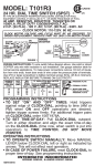
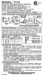
MODEL:
T104R3
24 HR. DIAL TIME SWITCH (DPST)
LR3730
IN TYPE 3R RAINPROOF ENCLOSURE SUITABLE FOR POOL
EQUIPMENT CONTROL IF INSTALLED 5 FT. OR MORE FROM EDGE OF POOL
40 AMP. RESISTIVE, PER POLE 120-480V. AC; 40 AMP.
INDUCTIVE OR TUNGSTEN OR 1000V.A. PILOT DUTY
PER POLE 120-277 V. AC; 2 H.P. (24 FLA) - 120 V. AC;
5 H.P. (28 FLA) - 240 V. AC
CLOCK MOTOR: 208-277V. 60 HZ.
CLOCK MOTOR VOLTAGE AND CYCLE MUST BE AS SPECIFIED. TO
ORDER REPLACEMENT, INDICATE PART NO. (WG--) ON MOTOR COVER.
WIRING
DIAGRAM
ON
CLOCK
TIME
240 V. 2 WIRE
MOTOR
TRIPPER AND GROUND
DIAL
TIME
POINTER
GR
240V. LINE 1
SUPPLY LINE 2
OFF
TRIPPER
MANUAL
LEVER
A
1
2
3
4
TO
LOAD
277/480 VOLT- CONNECT MOTOR LEADS TO TERMINALS
“A” AND 1 AND SUPPLY NEUTRAL TO TERMINAL “A”.
WIRING INSTRUCTIONS:
To wire switch follow diagram
above. Use solid or stranded COPPER only wire with insulation to suit
installation. See gauge selection table for normal service applications. To
make power connections remove 1/2 inch of insulation from wire ends.
Insert bare ends of wire under the pressure plate of terminals. Use 3/16 or
larger screwdriver to tighten terminal screws firmly. (25 lb-in minimum).
REPLACE INSULATOR BEFORE TURNING ON ELECTRICITY.
MINIMUM
COPPER
WIRE SIZE
(AWG)
MAX.
LOAD
(AMP)
MIN.
INSULATION
TEMP(°C)
14
12
10
8
15
20
30
40
60
60
60
75
75°C INSULATION MAX. MOTOR
LOAD (HP)
SINGLE PHASE
120 V.
240 V.
1/2
1
2
-
2
2 1/2
3
5
3 PHASE
208 V.
240 V.
N/A
N/A
PRESSURE PLATE
TERMINAL SCREW
MAKE SURE WIRE
INSULATION CLEARS
PRESSURE PLATE
PROGRAMMING INSTRUCTIONS
1. TO SET “ON” AND “OFF” TIMES: Hold trippers against edge of
CLOCK-DIAL, pointing to time (AM or PM) when ON and OFF operations are desired, tighten tripper screws firmly. See caution below. For
additional tripper pairs on CLOCK-DIAL order 156T1978A.
2. TO SET TIME-OF-DAY: Pull CLOCK-DIAL outward. Turn in either
direction and align the exact time-of-day on the CLOCK-DIAL (the time
now, when switch is being put into operation) to the pointer. DO NOT
MOVE THE POINTER.
OPERATING INSTRUCTIONS
• TO OPERATE SWITCH MANUALLY: Move MANUAL LEVER below
CLOCK-DIAL left or right as indicated by arrows. This will not effect
next operation.
• IN CASE OF POWER FAILURE, reset CLOCK-DIAL to proper timeof-day. See programming instructions.
INTERMATIC INCORPORATED
SPRING GROVE, ILLINOIS 60081-9698
158TS13085