1
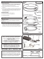
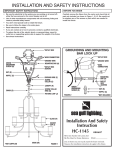
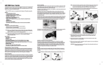
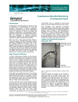
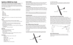
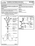
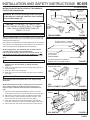
INSTALLATION AND SAFETY INSTRUCTIONS HC-670
U.S. PAT. # 5,465,199
INSTRUCTIONS FOR INSTALLATION OF THE AMBIANCE
STARTER SET 9888/9889/9890
12V WIRES
TRANSFORMER
12V PLUG
OUTLET
WARNING: Be sure the electricity to the wires you
are working on is shut off; either the fuse removed
or the circuit breaker off.
CAUTION: TO PREVENT THE RISK OF FIRE,
DO NOT INSTALL CLOSER THAN 2” TO CABINET
WALL OR IN A COMPARTMENT SMALLER
THAN 6” X 6” X 22”.
120V PLUG
(IF APPLICABLE)
120V CORD
120V
QUICKCONNECT
PLUG
SWITCH
TRANSFORMER INSTALLATION (FIGURE 1)
Select the desired location to mount transformer (not in contact with
insulation and away from oven or any other source of intense heat,
including other transformers).
TO PLUG (TO LIGHTS)
(IF APPLICABLE - CONNECT
SECOND PLUG TO LIGHTS)
Use screws to mount transformer to surface. Transformer can be mounted
in any direction. The wattage load on each output must be a minimum of
15w for the transformer to operate, but must not exceed 60w.
NOTE: (If Applicable). The transformer has an 8 foot 120 volt
cord with a plug molded at the end (FIGURE 1).
If you require the length of the 120 volt cord to be shorter, cut
and discard the excess 120 volt cord with molded plug. Follow
the instructions below on how to install 120 volt quick-connect
plug.
INSTALLATION OF 120V QUICK-CONNECT PLUG
1.
2.
3.
4.
Cut off end of 120v cord cleanly and evenly. CAUTION: Do not
separate wires. Do not remove or damage insulation
(Figure 3)
Press cord, with ridged side to the right (tracer wire), down and
into front of plug.
Press cord down onto metal prongs.
Slide plug cover over cord and plug until plug cover is centered
over plug.
FIGURE 1
TRANSFORMER
120V
12V
120 WATTS
(2 x 60 WATT)
TRANSFORMER
FROM 120V PLUG
THE INPUT/OUTPUT VOLTAGE IS
MARKED ON THE TRANSFORMER
FIGURE 2
NON-TRACER WIRE
COVER
120V
CORD
INSTALLING SWITCH ON 120V CORD
NOTE: Switch must be mounted a least 1 1/2” away from any
metal parts.
NOTE: When parallel wire (SPT I and SPT II) is used, the tracer
wire is square shaped or ridged and the non-tracer wire is
round in shape or smooth (seen best when viewed from wire
end).
1.
2.
3.
4.
5.
Split 120v cord as illustrated (FIGURE 4). Cut the non-tracer
(or smooth) wire. Be sure to cut only the smooth non-tracer wire.
Remove the screw from the switch and take the switch apart.
Place the wires in part A (without the wheel) as shown. Tuck
the cut wire down one end on each side of the barrier.
Press both halves of the switch back together. Note that the
points pierce insulation to make contact with copper inside wire.
Place screw back into center hole and secure in place with nut.
TRACER WIRE
120V
QUICK-CONNECT PLUG
SCREW
FIGURE 3
120V
CORD
PART A
NUT
NTS
POI
120V SWITCH
FIGURE 4
043003
TO INSTALL DISK LIGHTS
HC-670
SURFACE MOUNTING
1. Secure surface mount ring to surface by marking hole location on
surface and screw surface mount ring to surface making sure
surface mount ring does not flex out of round.
DISK LIGHTS
SURFACE
MOUNT
RING
NOTCH
2. Drill wire exit hole in surface or run wire thru notch in surface
mount ring.
3. Run the wires from disk lights to transformer plug outlet (Figure 6).
Line up retaining springs on fixture housing with grooves in surface
mount ring and press fixture housing into surface mount ring.
Insert lamp(s) (18w max.).
HOLES (2)
RECESS MOUNTING
GROOVES (2)
1. Drill a 2 3/4” dia. hole in surface (Figure 7).
2. Press fixture housing into 2 3/4” dia. hole.
3. Insert lamp(s) (18w max.).
RETAINING SPRING (2)
SCREWS (2)
FIXTURE
HOUSING
FINAL INSTALLATION
FROM DISK LIGHTS:
Insert disc light plug (one from each disk light) into transformer
plug outlet.
SLOTS (4)
TRIM INSTALLATION
LAMP
(18w max.)
1. Secure trim (not included) to fixture housing by inserting hooks,
on trim, into two of the four slots in fixture housing and twist
clockwise until trim snaps in place. Bend hooks up slightly (max.
1/8”) if trim is too hard to turn and lock into position on housing.
HOOKS (2)
*TRIM
1/8”
FIGURE 5
*NOT INCLUDED
TRANSFORMER
NOTE: As with all electronic transformers
there’s a potential for Radio Frequency
Interference (R.F.I.).
To reduce R.F.I., rotate the electronic
transformer in relation to the input line, or
switch to a magnetic transformer.
120V
INPUT
TRANSFORMER
PLUG OUTLET
DISC LIGHT
PLUG
DISC
LIGHT
WARNING: Use of other manufacturers
components will void warranty, U.L. listing
and create a potential safety hazard.
FIGURE 6
IMPORTANT SAFETY INSTRUCTIONS
This starter kit has a polarized plug (one blade is wider than
the other). As a safety feature, this plug will fit in a polarized
outlet only one way. If the plug does not fit fully in the outlet,
reverse the plug. If it still does not fit, contact a qualified electrician. Never use with an extension cord unless plug can be
fully inserted. Do not attempt to defeat this safty feature.
2 3/4”
DISK LIGHT
FIGURE 7