Transcript
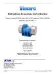
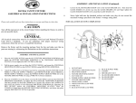
ASSEMBLY & INSTALLATION
INSTRUCTIONS
ASSEMBLY AND INSTALLATION (Continued)
6.
Place the CANOPY(23) on the fixture over the OUTLET BOX(1) and onto the
FIXTURE MOUNTING SCREWS(5), and adjust the FIXTURE MOUNTING
SCREWS(5) until they protrude out from the CANOPY(23)1/4”. Remove the
CANOPY(23) and secure the position of the FIXTURE MOUNTING SCREWS(5)
by tightening the HEX NUT(24) against the MOUNTING BRACKET(6). Place the
CANOPY(23) back onto the FIXTURE MOUNTING SCREWS(5), and secure into
place using the DECORATIVE NUT(9) provided.
7.
Unscrew and remove the THREADED SOCKET RING(18) from the EXTERIOR
THREADED SOCKET(16). Slide the center hole of the SHADE(17) over the
EXTERIOR THREADED SOCKET(16) and screw the THREADED SOCKET
RING(18) back onto the EXTERIOR THREADED SOCKET(16).
8.
Place a light bulb into the EXTERIOR THREADED SOCKET(16), with the type
and wattage rating specified on the lamp replacement marking located on the fixture.
Please read carefully and save these instructions, as you may need them at
a later date.
CAUTION
Turn off the main power at the circuit breaker before installing the fixture, in order to
prevent possible shock.
GENERAL
All electrical connections must be in accordance with local and National Electrical
Code (N.E.C.) standards. If you are unfamiliar with proper electrical wiring
connections obtain the services of a qualified electrician.
Remove the fixture and the mounting package from the box and make sure that no
parts are missing by referencing the illustrations on the installation instructions.
ASSEMBLY AND INSTALLATION
1.
Determine the desired length from the intended ceiling or mounting surface
that you wish the fixture’s SHADE(17) to extend down to. Using the three
different lengths of TUBES(12,13,14) provided, determine which
combination of tube lengths is going to give you your desired length and
screw the TUBES(12,13,14 ) together using the NIPPLE(11) provided.
Thread a NIPPLE(11) on each end of the assembled TUBES(12,13,14 ) to
be used on the fixture.
2.
Feed the SOCKET LEAD WIRES(7&22) from the SHADE HOLDER
UNT(19) through the TUBES(12,13,14) and the CANOPY(23). Screw the
components together until they secured and do not come loose.
3.
Place the #8-32 HEX NUTS(24) onto the #8-32 FIXTURE MOUNTING
SCREWS(5), and attach the FIXTURE MOUNTING SCREWS(5) to the
MOUNTING BRACKET(6), or universal mounting plate, (whichever is
provided). Do not tighten the HXE NUTS(24) at this time.
4.
Pull the power supply wire out from the OUTLET BOX(1), and mount the
MOUNTING BRACKET(6) or the universal mounting plate to the
OUTLET BOX(1),using MOUNTING SCREWS(20).
5.
Attach the power supply wire to the fixture lead wire by connecting BLACK
SUPPLY WIRE(4)to BLACK FIXTURE LEAD WIRE(22), and WHITE
SUPPLY WIRE(2) to WHITE FIXTURE LEAD WIRE(7). Connect the
FIXTURE GROUND WIRE(21) to the POWER SUPPLY GROUND WIRE
(3) using a WIRE CONNECTOR(8) (not included).
INSTALLATION IS NOW COMPLETED
1.
2.
3.
4.
5.
6.
7.
8.
9.
10.
11.
12.
13.
14.
15.
16.
17.
18.
19.
20.
21.
22.
23.
24.
OUTLET BOX
WHITE SUPPLY WIRE
POWER SUPPLY GROUND WIRE
BLACK SUPPLY WIRE
FIXTURE MOUNTING SCREW
MOUNTING BRACKET
WHITE FIXTURE LEAD WIRE
WIRE CONNECTOR
DECORATIVE NUT
SWIVEL
NIPPLE
18” TUBE
12” TUBE
6” TUBE
SOCKET CUP
EXTERIOR THREADED SOCKET
SHADE
SOCKET RING
SHADE HOLDER UNIT
MOUNTING SCREW
FIXTURE GROUND WIRE
BLACK FIXTURE LEAD WIRE
CANOPY
#8-32 HEX NUT
This product may not contain glass
shade. The drawing of glass shade
shown in this instruction is a
representative, it may not match the
glass shade you ordered.