1
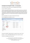
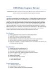
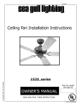
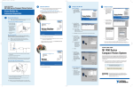
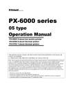
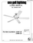
READ AND SAVE THESE INSTRUCTIONS
INSTRUCTIONS FOR MOUNTING THESE CENTER STEM
LIGHT FIXTURE: K1K, K2K, K4C
WARNING: To reduce the possibility of electrical shock, be sure that the power is turned off at its source
(fuse or circuit breaker). All electrical components must be installed in accordance with national and local
electrical codes. To reduce the risk of fire and electrical shock, this light fixture should be used only with
UL, ETL & CUL Certified Casablanca ceiling fans.
IMPORTANT: Before discarding any packing material locate the following items:
Fixture
Light Bulb(s)
Dimensions (w/glass)
Weight
K4C
4 - 60w A15 med base
9"h x 23"w
2 lbs
K1K
1 - 100w A19 med base
7"h x 9"w
3 lbs
K2K
1 - 100w A19 med base
6"h x 6"w
3 lbs
I N S TA L L AT I O N
1. Remove the cover from fan by removing two
brass 8-32 screws and save these screws for reattaching cover. Remove plastic wire nuts from
switch housing wires and strip 1/2" insulation from
both wires (black or blue, and white). Remove the
center plug from the cover. See FIG. 1
NOTE: If installing this light fixture on a 3
Speed pull-chain model fan, a separate pullchain switch (included with the fan) must be
installed. Refer to the following installation
instructions, otherwise skip to step 4.
2. Remove the plastic plug from the fan switch
housing. Install the light on-off switch by inserting
the chain through hole, from the inside. Pass the
switch threads into the hole and screw the knurl nut
onto the switch. Hand tighten firmly. See FIG. 2
3. Attach the blue wire from the fan to one of the
blue wires on the switch by twisting the bare ends
of the wires together. Secure the splice by threading on one of the wire nuts provided. Test the
secureness of the splice by pulling on the wire nut.
SWITCH
HOUSING
COVER
CENTER PLUG
8-32 SCREW
FIG. 1
WHITE WIRE
KNURL NUT
PLASTIC PLUG
BLUE WIRE
WIRE NUT
PULL-CHAIN
SWITCH
FIG. 2
9943520
REV. D
KG JUN03 8A000
4. Guide the two wires from the light fixture through
the center plug-hole in cover and then thread the
light fixture into the center hole. Hand tighten firmly.
See FIG. 3
5. While holding light fixture up to the fan, attach the
wires from the fan switch housing and the wires
from the light fixture together (black-to-black or
blue-to-black and white-to-white) by twisting the
bare ends of the wires together. Then secure the
splices by threading on the wire nuts provided. Test
the secureness of each splice by pulling on the wire
nut.
6. Re-attach the cover and light fixture to the fan
switch housing using the two brass 8-32 screws,
insuring guide pins are properly located into fan
switch housing.
Caution: Make sure no wires are pinched between
cover and switch housing. Tighten the screws to
secure light fixture.
7. Install glass (not included) by loosening the
thumbscrews on each shadeholder, align glass
inside shadeholder as far as it will go and tighten
thumbscrews equally around the glass. Make sure
the glass is snug and locked-down tight so that the
glass will not rattle when the fan is in operation.
8. Install the appropriate light bulbs.
Do not exceed the maximum wattage indicated
on the light fixture.
9. Connect the fob pull chain to the light pull chain.
WHITE WIRE
BLACK OR
BLUE WIRE
WIRE NUT
BLACK WIRE
GUIDE PIN
8-32 SCREW
THUMB SCREW
FIG. 3
LIGHT FIXTURE
EXAMPLE