1
Installation And Safety Instructions
HC-358
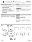
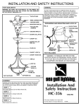
Line art shown may not exactly match the fixture enclosed. However, the installation instructions do apply to
this fixture. Fill in Item Number on Carton and File This Sheet For Future Reference. ITEM#_______________
040209
IMPORTANT SAFETY INSTRUCTIONS
•
•
•
•
•
•
•
•
Be sure the electricity to the system you are working on is turned
off; either the fuse removed or the circuit breaker set at off.
Use of other manufacturers components will void warranty, listing
and create a potential safety hazard.
If you are unclear as to how to proceed, contact a qualified
electrician.
You don’t need special tools to install this fixture.
Be sure to follow the steps in the order given.
Under no circumstances should a fixture be hung on house
electrical wires, nor should a swag type fixture be installed on a
ceiling which contains a radiant type heating system.
Read instructions carefully.
Save these instructions.
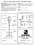
*OUTLET BOX
*WIRE CONNECTORS
*GROUND WIRE
MOUNTING BAR (A)
*OUTLET BOX
SCREWS
CLEANING
To clean, wipe fixture with a soft cloth. Clean glass with a mild soap.
Do not use abrasive materials such as scouring pads or powders,
steel wool or abrasive paper.
GROUND WIRE (F)
SCREW COLLAR (E)
ORDERING PARTS
CANOPY (H)
Keep this sheet for future reference, and in case you need to order
replacement parts. Parts for this fixture can be ordered from place
of purchase. Be sure to use exact wording from illustration when
ordering parts.
SCREW COLLAR
RING (G)
CHAIN (S)
BEFORE YOU BEGIN
FIXTURE LOOP (I)
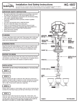
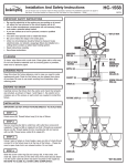
Carefully remove the fixture from the carton and check that all parts
are included, as shown in Figure 1. Be careful not to misplace any of
the screws or parts which are needed to install this fixture.
STEP 1:
RETAINING RING (L)
Attach loop (I) to top of fixture (if applicable).
DIFFUSER (J)
SOCKET (K)
INSTALLATION
IMPORTANT: DO NOT ATTACH FIXTURE DIRECTLY TO OUTLET BOX.
STEP 2:
Secure mounting bar (A) to outlet box with outlet box screws (not
supplied). Thread nut (B) on nipple (C) so that 3 threads are exposed
above nut (B). Thread nipple (C) into mounting bar (A) and secure
with nut (B). Attach screw collar (E) to nipple (C).
STEP 3:
Using 2 pairs of pliers, open one link of chain (S) and connect it to
the fixture loop (I) at the top of the fixture.
STEP 4:
Slide the screw collar ring (G) and canopy (H), in that order, over
chain (S). Open one link on the other end of the chain (S) and attach
it to the screw collar (E) which has been mounted to the ceiling
nipple (C).
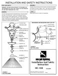
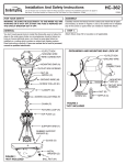
FIGURE 2
*NOT INCLUDED
INSTALLATION (continued)
HC-358
STEP 5:
Lace wires up through chain (S) and pass wires through holes in
screw collar (E). We recommend lacing wire up through every other
link of chain (S).
STEP 6:
A. Use a listed wire connector to connect the fixture hot wire (black
wire, or round and smooth tracer) to the supply hot wire.
B. Use a listed wire connector to connect the fixture common wire
(white wire, or square and rigid) to the supply common wire.
C. Gently try to remove the wires from the connector. If you can
remove the wires, carefully re-do the wiring connection.
STEP 7:
GROUNDING INSTRUCTIONS: The green grounding screw (D) is to
be inserted into the hole with two raised dimples provided on the
mounting bar (A). Wrap the ground wire (F) from the fixture (if
supplied) and the ground wire from the outlet box (bare metal or
green insulated wire) around the green grounding screw (D) on the
mounting bar (A) if uninsulated wire is on the mounting bar (A),
connect the ground wire (F) from the fixture (if supplied) and the
outlet box to it using a small wire connector (not supplied).
NEVER CONNECT GROUND WIRE TO BLACK OR WHITE POWER
SUPPLY WIRES.
FINAL ASSEMBLY
Make sure no bare wires can be seen outside wire connectors.
STEP 8:
After wires are connected, tuck them carefully inside outlet box and
then raise the canopy (H) against ceiling and screw the screw collar
ring (G) to the screw collar (E).
STEP 9:
Place diffuser (J) in socket assembly (K) and secure in place by
screwing retaining ring (L) onto socket (if applicable).
STEP 10:
Install lamps.