1
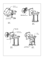
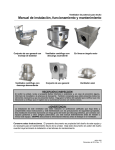
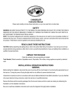
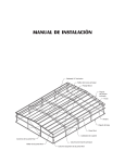
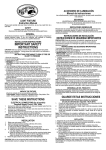
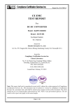
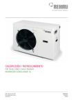
Luz de pared Manual de instrucciones
Lea cuidadosamente y guarde estas instrucciones, porque puede necesitarlas mas adelante.
SEGURIDAD
ADVERTENCIA: RIESGO DE DESCARGA ELECTRICA
Antes de instalar la luz de pared, desconecte el circuito de la red de suministro electrico.
INDICACIONES GENERALES
Efectue todas las conexiones electricas de acuerdo con las reglamentaciones municipales y nacionales vigentes. Si usted no
esta familiarizado con los metodos de instalacion del cableado electrico, contrate los servicios de un perito electricista
habilitado. Antes de iniciar la instalacion, corte la alimentacion electrica general con el interruptor principal o quitando los
fusibles de entrada.
Nota: Las importantes recomendaciones e instrucciones proporcionadas en este manual no abarcan todas las condiciones y/o
situaciones posibles que pudieran presentarse. Se sobreentiende que el sentido comun, la precaucion y la atencion al trabajo
no son parte de un producto. Son factores que debe tener en cuenta quien ejecute la instalacion de esta unidad.
INSTRUCCIONES DE INSTALACION
LEA Y CONSERVE ESTAS INSTRUCCIONES
PRECAUCION: ANTES DE COMENZAR LA INSTALACION, ASEGURESE DE QUE EL SUMINISTRO ELECTRICO ESTE
DESCONECTADO EN LA CAJA DEL CIRCUITO ELECTRICO. DESCONECTAR LA ENERGIA EN EL INTERRUPTOR DE
PARED NO ES SUFICIENTE PARA EVITAR DESCARGAS ELECTRICAS.
INDICACIONES GENERALES
1. Asegurese de leer estas instrucciones y revisar los diagramas con cuidado antes de instalar la luz de pared.
2. Todas las instalaciones electricas deben observar los codigos locales y el Codigo de Electricidad Nacional de
EE.UU. Si usted no esta familiarizado con los metodos de instalacion del cableado electrico, contrate los
servicios de un perito electricista habilitado.
3. Estos accesorios estan previstos para usar con una caja de empalme octogonal metalica de 4 x 2 1/8 pulg. (100 x 54 mm)
de profundidad. La caja debe ser soportada directamente por la estructura del edificio.
4. Antes de empezar con la instalacion, desconecte la alimentacion electrica con el interruptor general o los fusibles de
entrada. Cortar la alimentacion al circuito solamente con la llave de luz, no es suficiente para prevenir una electrocucion.
DESEMBALAJE DEL PRODUCTO
Verifique el contenido de la caja. Usted debe recibir:
- Paquete de herrajes de montaje
- Accesorio con soporte de montaje o placa trasera de apoyo y placa frontal.
PREPARACION DEL ACCESORIO
NOTA: En primer lugar, desconecte el suministro electrico
1. Si va a reemplazar un accesorio existente, desconecte y retire el accesorio antiguo y exponga el cableado de alimentacion
de la caja de conexion.
2. Si su accesorio se suministro con un vastago roscado, enrosque el vastago tres vueltas completas en el soporte de
montaje y fijelo a la caja de empalme con los tornillos provistos con dicha caja. Si su accesorio se suministro con dos
tornillos para metal, atornille los tornillos en el lado opuesto del soporte de montaje y fije el soporte a la caja de empalme
con los tornillos provistos con dicha caja. El extremo largo de los tornillos para metal o el vastago roscado deben mirar
hacia la habitacion.
3. Conecte el cable de tierra (verde o de cobre desnudo) desde el circuito de alimentacion al soporte de montaje con el
tornillo verde de conexion a tierra provisto. Algunos modelos cuentan con un cable de tierra conectado al accesorio. Sera
necesario conectar el cable verde o desnudo al cable de tierra del circuito de alimentacion.
4. Realice las conexiones electricas.
Wall Light Instruction Manual
Please read carefully and save these instructions, as you may need them at a later date.
SAFETY
WARNING: RISK OF ELECTRIC SHOCK
Disconnect the electrical supply circuit before installing wall light
GENERAL
All electrical connections must be in accordance with local codes, ordinances or national electrical codes. If you are
unfamiliar with methods of installing electrical wiring, secure the services of a qualified electrician. Before starting
installation, disconnect the power by turning off the circuit breaker or removing the fuse at the fuse box.
Note: The important safeguards and instructions appearing in this manual are not meant to cover all possible
conditions and situations that may occur. It must be understood that common sense, caution and care are factors
which cannot be built into any product. These factors must be supplied by the person installing this unit.
INSTALLATION INSTRUCTIONS
READ AND SAVE THESE INSTRUCTIONS
CAUTION: MAKE SURE POWER IS TURNED OFF AT THE ELECTRICAL PANEL BOX BEFORE BEGINNING
YOUR INSTALLATION. TURNING POWER OFF AT WALL SWITCH IS NOT SUFFICIENT TO PREVENT
ELECTRICAL SHOCK.
GENERAL
1. Be sure to read these installation instructions and review the diagrams thoroughly before installing the wall light
2. All electrical connections must be in accordance with local codes and the National Electrical Code. If you are
unfamiliar with methods of installing electrical wiring, secure the services of a qualified licensed electrician.
3. These fixtures are intended to be mounted to a 4 square x2 1/8 deep metal octagon outlet box. The box must be
directly supported by the building structure.
4. Before starting the installation, disconnect the power by turning off the circuit breaker or by removing the appropriate Fuse
at the fuse box. Turning the power off using the light switch is not sufficient to prevent electrical shock.
UNPACK THE FIXTURE
Check the contents of the box. You should receive:
. Mounting Hardware Package
. Fixture with Mounting Bracket or Back Mounting Plate and Front Face Plate
PREPARE THE FIXTURE
NOTE: First turn off electricity
1. If you are replacing an existing fixture, disconnect and remove the old fixture Expose the supply wiring from the outlet box
2. If your fixture is supplied with a threaded stem, screw the stem three complete turns into the mounting bracket
and fasten to the outlet Box with the screws supplied with the outlet box. If your fixture is supplied with two
machine screws, thread the machine screws into the opposite side of the mounting bracket and fasten the
bracket to the outlet box with the screws supplied with the outlet box. The long end of the machine screws or
threaded stem should be facing towards the room.
3. Attach the ground wire (green or bare copper) from the supply circuit to the mounting bracket with the green ground screw
provided. Some models have a ground wire attached to the fixture. It will be necessary to connect the green or bare
ground wire to the ground wire of the supply circuit.
4. Make electrical connections.
ELECTRICAL CONNECTIONS
Required Supply Circuit: 120V, 60Hz
Connect the white wire(s) from the fixture to the white wire of the supply circuit. Connect the black wire(s) from the fixture to the
black wire of the supply circuit. Connect the green or bare copper wire to the ground wire of the supply circuit. Use UL/CSA
listed wire connectors suitable for the size, type, and number of conductors. No loose strands or loose wires should be present.
Secure wire connectors with UL/CSA listed electrical tape.
FINAL ASSEMBLY
1. Make sure main power is off.
2. Install mounting bracket to existing outlet box with screws.(see step1)
3. Pull wires through mounting bracket. (see step2)
A, Make ELECTRICAL CONNECTIONS as directed above.
B, Carefully tuck connected wires back into the outlet box.
4. Place the front face plate over the mounting bracket, align the holes with either the thread stem or the machine
screws, and fasten with the decorative nut(s) provided. (see step3)
5. Outdoor wall fixtures must be caulked around the top and sides with RTV silicone caulking to reduce the chance
of water intruding into the splicing area.
Relamping: (see step 4)
1. Turn off power to the light fixture.
2. Push the mounting base near lamp shade, so that remain enough space to replace bulb.
3. Twist to remove bulb from the socket.
4. Replace with new bulb.
5. Replace mounting base back on the fixture.
6. Restore electrical power.
Caution: Refer to the relamping label located near the lamp holder for recommended maximum wattage.
CONEXIONES ELECTRICAS
Circuito de alimentacion requerido: 120 V, 60 Hz
Conecte el o los cables blancos del accesorio al cable blanco del circuito de alimentacion. Conecte el o los cables negros del
accesorio al cable negro del circuito de alimentacion. Conecte el conductor verde o de cobre desnudo al cable de tierra del
circuito de alimentacion. Use capuchones de empalme certificados por UL/CSA, adecuados para el tamano, tipo y cantidad de
conductores. No deben quedar conductores o cables sueltos. Asegure los capuchones de empalme con cinta aisladora
certificada por UL/CSA.
MONTAJE FINAL
1. Asegurese de que la alimentacion electrica este desconectada.
2. Instale el soporte de montaje en la caja de conexiones existente con los tornillos (consulte el paso 1).
3. Pase los cables a traves del soporte de montaje. (Consulte el paso 2).
A. Haga las CONEXIONES ELECTRICAS como se explica mas arriba.
B. Vuelva a colocar con cuidado todos los cables conectados adentro de la caja de conexiones.
4. Coloque la placa frontal sobre el soporte de montaje, alinee los orificios con el vastago roscado o con los
tornillos para metal, y fijela con la o las tuercas decorativas provistas. (Consulte el paso 3).
5. Pueden enmasillarse los apliques de exterioes alrededor de la parte superior y los costados con un compuesto
de enmasillado de silicona RTV para disminuir las probabilidades de que entre agun en el area del empalme.
Cambio de bombillas: (consulte el paso 4)
1. Desconecte la alimentacion del accesorio de iluminacion.
2. Empuje la base de montaje cerca de la pantalla de la lampara, de modo de obtener suficiente espacio para
cambiar la bombilla.
3. Gire la bombilla para retirarla del zocalo.
4. Reemplacela por la nueva bombilla.
5. Vuelva a colocar la base de montaje en el accesorio.
6. Restablezca la energia electrica.
Precaucion: Para el vatiaje maximo recomendado, consulte la etiqueta sobre el cambio de bombillas situada cerca
del portalamparas.
Outlet box
Caja de empalme
Wire connector
Capuchones de empalme
Mounting bracket
Soporte de montaje
Step1
Paso 1
Step2
Paso 2
Front cover
Tapa frontal
Decorative nut
Tuerca decorativa
Bulb
Bombilla
Step3
Paso 3
Mounting base
Base de montaje
Step4
Paso 4