Transcript
INSTALLATION INSTRUCTIONS
For Model 970-1-138
WARNING!
S H U T P O W E R O F F AT F U S E O R C I R C U I T B R E A K E R .
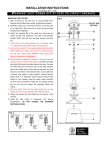
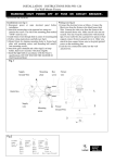
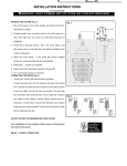
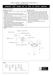
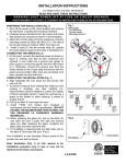
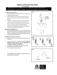
MOUNTING THE BACKPLATE(Fig.1)
1. Shut off the power at the circuit breaker and remove old
Fig. 1
fixture, including the crossbar.
2. Carefully unpack your new fixture and lay out all the parts on
a clear area. Take care not to lose any small parts necessary
for installation.
3. Attach the crossbar (A) to the outlet box using two outlet Box
Screws (B). The side of the Crossbar marked “GND” must face
out.
4. Thread the nipple (C) part way into the center hole of the
crossbar.
CONNECTING THE WIRES (Fig. 2)
1. At the point, connect the electrical wires as follows, Connect
the black wire from the fixture to the black house (hot) wire.
Connect the white wire from the fixture to the white (neutral)
house wire. Make sure all wire nuts are secured. You may
wrap the connections with electrical tape. If your outlet has a
ground wire (green or bare copper)connect fixture’s ground
wire to it. Otherwise connect fixture’s ground wire directly to
the crossbar using the green screw provided.
MOUNTING FIXTURE AND SHADE
Fig. 2
FIXTURE
WIRES
Black or
Smooth
FIXTURE
WIRES
White or
Ribbed
FIXTURE
WIRES
Bare
Copper
(Ground)
1. After the wires are connected tuck them carefully inside the
outlet box as you place the Backplate (F) over the nipple (C).
Secure the Backplate (F) against the wall using Knurled Cap
(D).
2. Install glass shade (E) by referring to fig 1.
3. Install light bulbs in accordance with fixtures specifications, DO
NOT EXCEED MAXIMUM WATTAGE RATING!
Your installation is now complete. Return power to the
junction box and test the fixture.
MIN 90℃ SUPPLY CONDUCTORS
HOUSE
WIRES
Black
(Hot)
HOUSE
WIRES
White
(Neutral)
HOUSE
WIRES
Green or
Bare
Copper(Gr
ound)