1
INSTALLATION INSTRUCTIONS FOR 4351-593
WARNING! SHUT
POWER
OFF AT
FUSE OR
CIRCUIT
BREAKER .
AVERTISSEMENT! COUPER LE COURANT AU NIVEAU DES FUSIBLES OU DU DISJONCTEUR.
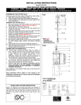
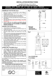
HANGING THE FIXTURE (Fig. 1)
1. Shut off the power at the fuse box or circuit breaker. If
necessary, remove the old fixture, including the mounting
hardware.
Fig.1
2. Carefully unpack the new fixture and lay out all the parts on
a clear area. Take care not to lose any parts necessary for
installation.
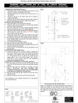
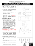
SUGGESTED INSTALLATION (Fig. 2)
3. Attach the mounting plate (A) to the junction box using
screws (B) (Size: #8-32*1/2"L). The side of the mounting
plate marked “GND” must face out.
4. Determine the desired hanging height and thread rods (F1,
F2,) to fixture body (G), determine correct number of links of
the chain (E) needed for proper hanging height. Using proper
chain pliers disconnect and discard remaining chain. Pass the
wires carefully through each rod and the chain (E) as you
assemble.
5. Feed wire through the canopy (C), connecting canopy (C) to
part (F1) and turn clockwise until firmly tightened.
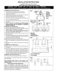
CONNECTING THE WIRES (Fig. 3)
6. At this point, connect the electrical wire as shown in figure 3,
making sure that all wire connectors are secured. If your
outlet box has a ground wire (green or bare copper), connect
the fixture’s ground wire to it. Otherwise connect fixture’s
ground wire directly to the mounting plate with the ground
screw (Size: #8-32*3/8"L) provided. After wires are
connected, tuck them carefully into the ceiling junction box.
COMPLETING THE INSTALLATION (Fig. 1)
7. Place the canopy (C) over the mounting plate (A) and secure
it with the brass ball (D).
8. Attach the glass shade (H) onto the socket of the fixture body
(G), and then lock it securely with the socket ring (I) .
9. Install the light bulb (not included) in accordance with the
fixture’s specifications: DO NOT EXCEED THE
MAXIMUM WATTAGE RATING! (NE PAS DEPASSER
LA PUISSANCE NOMINALE MAXIMALE!)
Your installation is now complete. Return power to the
junction box and test the fixture.
Fig.3
FIXTURE
WIRES
Black or
Smooth
Page:1/2
HOUSE
WIRES
Black
(Hot)
FIXTURE
WIRES
White or
Ribbed
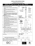
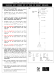
CHAIN HUNG FIXTURE INSTRUCTION
Notice: It is important to use proper chain pliers (not included) To
OPEN and CLOSE the chain included with this fixture. Do not
open them with other tools that may twist or stress the chain links.
It is important to use proper chain pliers like the ones shown in
the diagram
FIXTURE
WIRES
Bare
Copper
HOUSE (Ground) HOUSE
WIRES
WIRES
Green or
White
Bare Copper(Ground)
(Neutral)
CM
C
US
lntertek
Fig.2
a. Hardware Bag:
A. Mounting Strap*1
B. Screw*2
C. Canopy*1
D. Brass Ball*2
E. Chain 12”*1
Wire Connector*3
b. Hardware Bag:
F1. ROD 6"*1
F2. ROD 12"*3
Page:2/2