Transcript
INSTALLATION INSTRUCTIONS
For Model # 1182/1183-357 (New 01/17/2003)
WARNING!
S H U T P O W E R O F F AT F U S E O R C I R C U I T B R E A K E R .
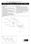
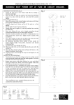
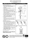
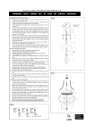
ASSEMBLING THE FIXTURE (Fig.1)
1. Carefully remove the fixture from the carton and check that
all parts are included as shown in the illustration.
2. Slide Glass Shade (D) along with Plastic Washer (E) and Iron
Washer (F) over Pipe (C), then secure them using Nut (A)
tightly.
3. Connect rod side and shade support together by threading
Nipple (J) into Coupling (K).
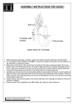
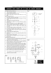
HANGING THE FIXTURE (Fig. 2)
4. Shut off power at the circuit breaker and remove old fixture
including the crossbar.
5. Thread Nipple into Loop until snug.
6. Thread other end of Nipple with Loop attached into crossbar
until snug.
7. Place Lock Washer over end of Nipple protruding through
crossbar and thread Hex Nut onto nipple until tight.
8. Take this crossbar assembly and mount to ceiling junction
box with junction box screws. Tighten screws securely with
screwdriver.
9. By measuring determine correct number of links needed for
proper hanging height.
10. Use a pair of pliers to open one end link of the chain, attach
the chain to the fixture’s loop, and close the link. Slip Loop
Collar and Canopy over the chain. Open the other end link of
the chain and lift the fixture to attach to the ceiling loop, close
the chain link.
11. Lace the fixture’s wires through the chain links and pull until
taut. Feed the fixture wires through the loop and Nipple and
pull until taut.
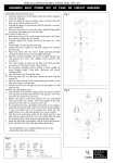
CONNECTING THE WIRES (Fig. 3)
12. At this point, connect the electrical wire as shown in figure 3,
making sure that all wire connectors are secured. If your
outlet has a ground wire (green or bare copper), connect the
fixtures Ground Wire to it. Otherwise, connect the fixture
Ground Wire directly to the crossbar using the Green Screw
provided.
13. Tuck these wire connections neatly into the ceiling junction
box and then raise the canopy all the way to the ceiling.
Raise the Lock Collar and thread onto ceiling Loop protruding
through canopy.
14. Install the light bulbs in accordance with the fixture’s
specifications. (DO NOT EXCEED THE MAXIMUM
WATTAGE RATING!)
15. (Fig. 4) Place the Glass Bulb Shields (P) over the Studs (L)
located on the Support Plate (N). Place Washers (M) over the
Studs (L) and tightly secure with Knurled Knobs (O).
Fig. 1
J
K
D
F
A
E
C
Fig. 2
Junction Box
(Ceiling)
Hex Nut
Lock Washer
Crossbar
Screw
Nipple
Loop
Chain
Canopy
Lock Collar
Your installation is now complete. Return power to the
junction box and test the fixture.
Fig. 4
Fig. 3
O M
FIXTURE
WIRES
Black or
Smooth
P
L
A
FIXTURE
WIRES
White or
Ribbed
FIXTURE
WIRES
Bare
Copper
(Ground)
N
HOUSE
WIRES
Black
(Hot)
LA-685E
HOUSE
WIRES
White
(Neutral)
HOUSE
WIRES
Green
(Ground)