Transcript
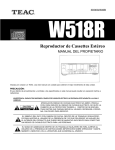
INSTALLATION INSTRUCTIONS
Item# 1359-177 (03/16/2009)
READ AND SAVE THESE INSTRUCTIONS
W A R N I N G ! S H U T P O W E R O F F AT F U S E O R C I R C U I T B R E A K E R .
ASSEMBLING THE FIXTURE (Fig.1)
1. Carefully remove the fixture from the carton and check
that all parts are included as shown in the illustration.
2. Shut off power at the circuit breaker and remove old
fixture including the mounting hardware.
3. Secure the upper Poly Assembly (A) to Light Cluster
Assembly (H), pull the wires from top Loop until taut.
4. Align the pre-drilled holes on the Arm (B) to the Stud (I)
on the bottom of upper Poly Assembly (A) and Point (K)
on the top of upper Poly Assembly (A) and secure them
with Cap Nut (J) and Thumb Screw (C) separately.
5. Adjust the Arms (G1, G2 and G3) on the Light Cluster
Assembly (H) to the proper position as shown in Fig.1.
6. Screw the Finial (F) to the bottom of Light Cluster
Assembly (H).
7. Screw the Glass Shade (D) over the Socket Cup (E) by
twisting it clockwise as shown in Fig.1
8. Install the light bulbs (not included) in accordance with the
fixture’s specifications. (DO NOT EXCEED THE
MAXIMUM WATTAGE RATING!)
HANGING THE FIXTURE (Fig. 2)
IMPORTANT: For a safe and secure installation, these
fixtures must be installed by means of support that is
independent of the outlet box.
SUGGESTED INSTALLATION:
9. Provide a 1/4 IPS pipe with one end securely mounted to
a beam or a structural member. The other end should
protrude through the center of the outlet box as shown.
10. Assemble the ceiling loop, nipple, nuts and hickey to
center 1/4 IPS support pipe and adjust overall length to
allow the ceiling loop to hold the canopy flush to the
ceiling. When the adjustments have been completed,
secure the three nuts, as shown.
11. Attach the chain to the fixture loop. Slip the lock collar
and canopy over the upper end of the chain. Open the
end link of chain and lift the fixture to attach to the ceiling
loop and secure the link.
12. Lace the fixture wires, ground and safety cable through
the chain and loop, exiting through the side of hickey. Run
cable through the top of the outlet box and secure to
structural member, locking with the set screw assembly.
CONNECTING THE WIRE (Fig. 3)
13. At this point, connect the electrical wire as shown in
figure 3, making sure that all wire connectors are
secured. If your outlet has a ground wire (green or bare
copper), connect the fixtures Ground Wire to it. If not,
consult your electrician for proper grounding.
14. Tuck these wire connections neatly into the ceiling
junction box and then raise the canopy all the way to the
ceiling. Raise the Lock Collar and thread onto ceiling Loop
protruding through canopy.
Your installation is now complete. Return power to the
junction box and test the fixture.
Note: Illustration (Fig. 1) on this manual is for
installation purposes only. It may or may not be
identical to the fixture purchased.
Fig. 1
G1
G3
A
K
B
C
G2
I
J
D
E
G1
G2
H
G3
F
Fig. 2
Set Screw Assembly
1/4IPS(1/2 dia.)pipe
(Not provided)
Safety cable
To structural member
Fixture wires
Fixture
Ground wire
Hickey
Nipple
Hex Nut
Ceiling loop
Lock Collar
Canopy
Chain(End link)
Fig. 3
FIXTURE
WIRES
Black or
Smooth
FIXTURE
WIRES
White or
Ribbed
HOUSE
WIRES
Black
(Hot)
Notice: It is important to use proper chain pliers (not
included)
To OPEN and CLOSE the chain included with this
fixture. Do not open them with other tools that may
twist or stress the chain links. It is important to use
proper chain pliers like the ones shown in the diagram.
FIXTURE
WIRES
Bare
Copper
(Ground)
HOUSE
WIRES
White
(Neutral)
HOUSE
WIRES
Green
(Ground)
LA-1411E