1
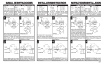
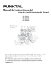
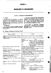
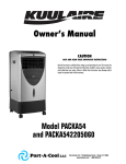
LQM L.E.D. Exit Sign
US Patent No. 5,611,163, 5,739,639 and 5,526,251
US Patent No. 5,954,423, 5,988,825, 6,152,581, 6,502,044,
D495,751, and D383,501
Canada Patent No. 2,204,218. Other Patents Pending.
INSTALLATION INSTRUCTIONS
INSTRUCCIONES DE INSTALACION
IMPORTANT
SAFEGUARDS
DIRECCIONES
DE SEGURIDAD
1.READ AND FOLLOW ALL
SAFETY INSTRUCTIONS
1. LEA Y SIGA TODA LAS INSTRUCCIONES DE
SEGURIDAD
2. Before wiring to power supply, turn off
electricity at fuse or circuit breaker.
3. Disconnect A.C. power before servicing.
4. All servicing should be performed by
qualified personnel.
5. Consult your local building code for approved wiring and installation.
6. Do not use outdoors.
7. Do not mount near gas or electric heater.
8. Fixture must be grounded to avoid potential
electric shock.
9. Equipment should be mounted in location
and at heights where it will not readily be
subjected to tampering by unauthorized
personnel.
10.
The use of accessory equipment not
recommended by the manufacturer may
cause an unsafe condition.
11.
Do not use this equipment for other than
intended use.
2. Antes de instalar los cables al suministro de energia
electrica corte la corriente al fusible o caja de circuito.
3. Corte la corriente CA antes de mantener.
4. Todo mantenimiento debe ser hecho por personal
capacitado.
5. Consulte el codigo de construccion local para cables e
instalacion electrica aprobado.
6. No utilize en el exterior.
7. No lo instale cerca a calentadores electricos o de gas.
8. Tome precauciones cuando este manteniendo las baterias.
Corte la corriente CA antes de mantener las baterias.
9. Este equipo se debe instalar en un sitio y a una altura donde
no este expuesto a personal sin autorizacion.
10. El uso de este accesorio que no sea recomendado por el
fabricante puede causar una condicion peligrosa.
11. No use este equipo en una forma diferente a lo que esta
intencionado.
SAVE THESE
INSTRUCTIONS
GUARDE ESTAS
INSTRUCCIONES
Mounting Bracket
Soporte de la Caja Electrica
Sign Panel
Panel del Aviso
Canopy
Capota
Directional Chevrons
Flechas Direccionales
PCB Cover
La Cubierta del Tablero de circuitos
Cam-Lock Pin
Clavija de Seguridad
Mounting Hole Cover
Cuvierta Lateral
Faceplate
Cuvierta Delantera
Battery
la Bateria
(EL Only)
Housing
Caja
Circuit Board
Tablero de Circuito
Back Cover
Cuvierta Tracera
TOP/SIDE MOUNT
INSTALACION PARA ENCIMA O DE LADO
1
Connect provided jumper leads to AC input in J-Box.
Using keyhole slots insert screws through bracket.
Conecte los cables dados a input de CA dentro de caja
electrica. Conecte los alambres a la entrada de la C.A.
en la caja J. Usando ranuras de ojo la cerradura meten
los tornillos por parentesis.
4
Dress leads through Housing wire channel. Snap
Housing onto Canopy. Insert proper input wires into
corresponding pushnut to connect power to unit.
Pase los cables por el canal en la caja. Asgure la caja a
la capota. Meta alambres apropiados en el pushnut
corresponiente para conectar el poder del equipo.
2
Rotate bracket to desired alignment position and tighten
screws. Be careful not to over-tighten screws, as this
may cause misalignment of canopy to mounting surface.
3
Place canopy over mounting bracket.
Coloque la capota sobre el parentesis que monta.
Gire parentesis a la posicion descada del alignment y
apriete. Tener cuidado de no apretar mucho los tornillos,
esto puede causar un desaliniamiento de la montura y la
supeficie de montar.
5
Snap Cam-Lock Pin into retaining hooks. Rotate handle
of locking pin up to lock.
Asegure la clavija de seguridad a los ganchos. Gire la
manija de cerrar hasta que cierre.
6
Snap Faceplate onto Housing.
Asegure la cuvierta delantera a la caja.
GENERAL INFORMATION
INFORMACION GENERAL
To remove directional Chevrons; remove
colored sign panel and push Chevron from
rear of panel.
Power PCB Cover should always be installed as shown
except in mounting configurations where the back
cover is installed on the reverse side.
On Emergency units with a battery, plug battery
connector onto the circuit board to complete installation
after continuous power has been applied.
Para quitar las flechas direccionales quite
el panel de color del aviso y empuje la
flecha por detras de la cuvierta delantera.
La Cubierta de TCI de poder siempre se debe insalar
como mostrada menos a montar configuraciones
donde la cubierta de espalda se instala enel lado
inverso.
En equipo de Emergencia con una bateria, tape el
conector de bateria en el tablero de circuitos para
competar la instalacion despues de que se haya
aplicado la energia continua.
Dress leads through center knockout in Back
Cover. Fasten Back Cover to J-Box. Snap
Housing onto Back Cover.
120 or 277 V - Connect input leads to Circuit Board
leads using provided pushnuts. See wiring
diagrams.
Pase los cables por la apertura central en la
cuvierta tracera. Asegure la cuvierta tracera a la
caja. Asegure la caja a la cuvierta tracera.
120 o 277V - Conecte cables de input a los cables
del Tablero de Circuito usando los connectadores
dados. Vea esquema del cableado.
To remove Canopy, remove Cam-Lock
Pin, squeeze snaps and push out.
To remove Back Cover press in and
release latches and snaps.
Para quitar capota, apriete ganchos y
enpuje afuera.
Para quitar la cuvierta tracera apriete y
suelte los ganchos.
INSPECTION AND MAINTENANCE (EL N ONLY)
INSPECTION ET ENTRETIEN (Solemente de EL N)
Inspection et entretien
NOTE: Emergency lighting systems should be tested as often as
local codes require, or at least quarterly, to ascertain that all
components are operational.
NOTA: Sistemas de Iluminacion de Emergencia se deben probar
con la frequencia requerida por codigos locales, o por lo menos
cada tres meses para asegurarse que todas las partes esten
funcionando.
NOTE: Allow battery to charge 24 hours before initial testing,
and
168 hours to fully charge battery.
NOTA: Deje que la bateria se carge 24 horas antes de probar
por primera vez y 168 horas para completamente cargar la
bateria.
WARRANTY
FIVE-YEAR TOTAL CUSTOMER SATISFACTION
Complete Customer Satisfaction...This fixture is guaranteed to perform to our
customers’ complete satisfaction for a period of five years from date of invoice.
Our guarantee covers any defect in manufacturing, provided the defect develops
under normal and proper use. This liability extends only to replacement of the
defective part. Labor charges will be honored by the factory only with prior written
approval from our Post Sales Service Department.
GARANTIA
SATISFACCION TOTAL PARA EL CLIENTE POR CINCO ANOS
Satisfaccion Completa del Cliente...Este equipo esta garantizado a trabajar a la
satisfaccion total del cliente por cinco anos de la fecha en la factura. Nuestra
garantia incluye cualqier defecto en fabricacion, con tal de quel defecto se creo
bajo uso normal y correcto. Esta responsabilidad incluye solamente el remplaso
de la parte defectiva. La fabrica aceptara pagar por el trabajo solamente con la
aprobacion por escrito de nuestro departamento de servicios de marketing.
WIRING DIAGRAM
ESQUEMA DEL CABLEADO
BATTERY REPLACEMENT:
CAUTION: Prolonged absence of AC power could cause
battery damage.
PRECAUCION:
Falta de corriente CA por mucho tiempo
puede cau`sar daño a la bateria.
Power Supply
Corriente de input
White: Neutral
Blanco:
Black: 120V
Negro:
Orange: 277V
Naranja:
LED Circuit Board
Tablero de Circuito
Remove A.C. power from unit. Remove battery from housing
location and unplug from circuit board. Replace battery only with manufacturer's recommended
replacement. Install replacement battery and reconnect on Circuit Board .
REMPLASO DE LA BATERIA: Corte la corriente CA del equipo. Quite la bateria de la
localizacion de la cubierta y desenchfela del tablero de circuito. Substituya la bateria solamente
por el reemplaza recomendado del fabricante. Instale la bateria del reemplazo y vuelva a conectar
en el tablero de circuito.
Battery (EL Only)
Bateria (Solemente de EL)
Ready Light (EL ONLY)
Luz Ready
Test Switch (EL Only)
Boton de Prueba
EMERGENCY LIGHTING SYSTEMS
TEL: 800-334-8694 Fax: 770-981-8141 www.lithonia.com
EMCSA00713
Rev C