Transcript
INSTALLATION INSTRUCTIONS For Fixture #4930
WARNING! SHUT POWER OFF AT FUSE OR CIRCUIT BREAKER.
AVERTISSEMENT! COUPER LE COURANT AU NIVEAU DES FUSIBLES OU DU DISJONCTEUR.
BREAKER.
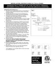
PREPARING THE FIXTURE (FIG. 1)
1. Shut off the power supply at the fuse box or circuit breaker. If
necessary, remove the old fixture from ceiling, including the
mounting hardware.
2. Carefully remove the fixture from the carton and check that all
parts are included as show in Figure 1.
MOUNTING THE FIXTURE (FIG. 2)
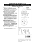
3. Thread the 2 mounting screw (F) about 1/4” into the
pre-drilled holes in the Crossbar (G) spaced the same
distance apart as the holes in the fixture. (See Fig.1)
4. Attached the Cross bar (G) to the outlet box using the 2 Outlet
Box Screws (E). The side of the Cross bar (G) marked “GND”
must face out.
5. While holding the steel pan (I) towards the Crossbar (G),
connect the electrical wires as shown in figure 2. If your outlet
has a ground wire (green or bare copper), connect the fixture
Ground Wire to it. Otherwise, connect the fixture ground wire
directly to the crossbar using the green screw provided. Make
sure that all wire connectors are secured. Tuck the wire
connections neatly into the ceiling junction box as you are
holding the fixture assembly toward the ceiling.
6. Finishing mounting the fixture pan (I) by placing it over both
mounting screws (F) so that the screws protrude through the
key holes in the steel pan (I). Rotate the pan (I) until the
screws are seated in the slots of the key holes and tighten the
screws with a screwdriver.
7. Thread the Nipple (M) into the Coupling (J). The lower nipple
length could be adjusted and secured by adjusting the
location of the hex nut on the Nipple (M) to install the lower
parts of the fixture.
8. Install the light bulbs in accordance with the fixture’s
specifications. (DO NOT EXCEED THE MAXIMUM
WATTAGE RATING!) (NE PAS DEPASSER LA PUISSANCE
NOMINALE MAXIMALE!).
9. Insert the glass shade (L), plastic washer (H), Flat Washer (N)
over the center nipple (M) in that order, then secure with hex
nut (O).
10. Insert the bottom cap (P) on to the center nipple (M) and
thread the finial (Q) onto the center nipple (M) until snug.
Your installation is now complete.
Return power to the junction box to test the fixture.
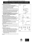
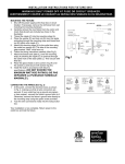
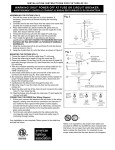
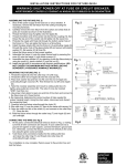
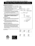
Fig.1
Set A#A-010
-Crossbar
-Ground Screw
-Mounting screws (2)
MOUNTING SCREW(F)
SOCKET(K)
COUPLING(J)
NIPPLE WITH HEX NUT(M)
GLASS SHADE(L)
PLASTIC WASHER(H)
FLAT WASHER(N)
HEX NUT(O)
CAP(P)