Transcript
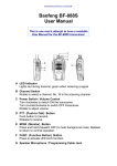
LOW VOLTAGE OUTDOOR LIGHTING
INSTALLATION INSTRUCTION
1. POWER CONNECTOR
2. GROUND STAKE
3. EXTENSION PIPE 3
4. EXTENSION PIPE 2
5. EXTENSION PIPE 1
6. SCREW
7. HOOD
8. BULB COVER
9. CAGE
INSTRUCTIONS PERTAINING TO A RISK OF FIRE, OR
INJURY TO PERSONS - IMPORTANT SAFETY INSTRUCTIONS
- SAVE THESE INSTRUCTIONS
WARNING - To reduce the risk of FIRE OR INJURY TO PERSONS:
1.
2.
3.
4.
5.
6.
A lit lamp is very HOT. Turn off light and allow to cool before touching replacing lamp.
Lamps get HOT quickly! Only contact switch / plug when turning on. Never install lamp
when the light is connected to power.
Do not touch hot lens, guard, or lamp enclosure.
Keep lamp enclosure away from flammable and/or combustible material.
Avoid touching the glass tubing of the lamp. Use a soft cloth when handling the lamp. Oil
from skin may cause the lamp to explode when lit.
Do not operate the lam with a missing or damaged bulb cover.
Fig. 1
ASSEMBLY
1.
2.
3.
4.
5.
Attach EXTENSION PIPE 2 to EXTENSION PIPE 1 and EXTENSION PIPE 3 to
EXTENSION PIPE 2.
Thread the GROUND STAKE (2) onto the bottom of EXTENSION PIPE 3 and tighten
securely. Pull any power cord slack from the GROUND STAKE thru the provided hole.
Insert a light bulb into the lampholder. Be sure that it does not exceed the maximum
wattage specified on the fixture’s wattage rating label.
Attach BULB COVER (8) to the lampholder clip.
Secure the CAGE (9) onto the HOOD (7) using the SCREW (6).
CORD GUIDE
“FACE UP”
CORD
CONNECTION TO LOW VOLTAGE POWER SUPPLY
CAUTION: CONNECT FIXTURE TO ONLY TO A 12 VOLT AC POWER SUPPLY
CIRCUIT. THE SUPPLY CIRCUIT MUST BE ELECTRICALLY ISOLATED FROM ALL LINE
VOLTAGE CIRCUITS. THE UNIT SECONDARY WIRING SHALL BE PROTECTED BY
ROUTING IN CLOSE PROXIMITY TO THE LUMINAIRE OR FITTING, OR NEXT TO A
BUILDING STRUCURE SUCH AS A HOUSE OR DECK. THE WIRING SHALL NOT BE BURIED
EXCEPT FOR A MAXIMUM 6 INCHED IN ORDER TO CONNECT TO THE MAIN SECONDARY
WIRE. THE WIRE SHALL HAVE THE LENGTH CUT OFF SO THAT IT IS CONNECTED TO A
CONNECTOR WITHIN 6 INCHES FROM A BUILDING STRUCTURE, A LUMINAIRA, OR
FITTING.
This product is designed to be installed onto a two-wire thermoplastic insulated cord. (Note: If
additional lengths of cord are needed for installation, they may be purchased at the local Home
Depot or hardware store.) To fasten the fixture to a low voltage cord:
Remove the threaded cap from the power connector and two plastic cord guides to expose
wiring channel.
2. Depending on the thickness of the cord, the installer must determine which of the following
methods to use:
A. For very thick cord - Lay the cord in the wiring channel aligning the spike terminals with
the center of each wire of the cord. Push the cord into the terminals until each spike
terminal pierces thru each wire of the cord. Lay the cord guide “face up” against the top of
the cord inside the channel. Replace the threaded cap. Be sure to secure the cap tightly.
See Fig. 2. Discard the remaining cord guide.
B. For thinner cord - Fasten one of the cord guides around the cord. See Fig. 3. (Note: The
cord guides are not the same. Each cord guide is different as they can accommodate a
different sized cord. The installer must determine which cord guide to fasten to the cord.)
Push the cord and the cord guide “face down” into the wire channel until each spike
terminal pierces thru each wire of the cord. Replace the threaded cap. Be sure to secure the
cap tightly. See Fig. 4.
NOTE: Be sure that the spike terminals pierce the center of each wire of the cord. If good
connection is not made, repeat the above steps.
Fig. 2
THREADED CAP
CORD GUIDE
CORD
Fig. 3
1.
THREADED CAP
CORD GUIDE
“FACE DOWN”
Fig. 4
CORD
INSTALLATION
CAUTION: DO NOT INSTALL THE LIGHT FIXTURE WITHIN 10 FEET OF A POOL, SPA,
OR FOUNTAIN. BE SURE NOT TO BURY ANY WIRING AND THE POWER CONNECTOR
DEEPER THAN 6 INCHES BELOW THE GROUND SURFACE. ROUT ANY WIRING OR CORD
IN CLOSE PROXIMITY OF A BUILDING STRUCTURE, SUCH AS A HOUSE OR DECK.
1.
2.
3.
Select the location of installation.
Place the tip of the GROUND STAKE against the ground surface, while holding the fixture
perpendicular to the ground.
Press down against the top of the GROUND STAKE to force it into the ground. Continue
to press down until the GROUND STAKE is completely buried into the ground.
Fig. 5