1
Water Filtration
Installation
Instructions
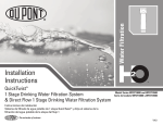
QuickTwist™
2 Stage Drinking Water Filter
Model Series WFQT27000
Model Series WFQT27300
Serie del modelo WFQT27000
Serie del modelo WFQT27300
Instrucciones de instalación
Sistema de filtrado de agua potable de 2 etapas QuickTwist™
V4.0
Installation Instructions
QuickTwist™
2 Stage Drinking Water Filtration Systems
Package Contents
A
System Head with
Built-in Bracket
DuPont Part No. WFAH200
D
Faucet for
Filtered Water
B
QuickTwist™
Filters
E
Black
Rubber Gasket
1
F
2
Parts & Hardware Included
A Filter System Head with Built-in Bracket
B 1 (1) QuickTwist™ 1st Stage Filter
2 (1) QuickTwist™ 2nd Stage Filter
C Mounting Screws
D Faucet for Filtered Water
E Black Rubber Gasket
F Metal Lock Washer
G Faucet Stem Nut
H Kitchen Faucet Adapter
I Insert
J Ferrule
K Compression Nut
L 1/4" Plastic Tubing
Metal Lock Washer
Tools & Materials Required
n
n
n
n
n
n
n
n
n
n
n
n
n
Faucet Stem Nut
1/8" Drill Bit
Adjustable Wrench
Utility Knife
Tape Measure
Safety Glasses
Masking Tape
Newspaper or Towels
Pencil
Pan or Bucket
Optional Materials
n
G
Phillips Screwdriver
n
Drill with 1/4" & 9/16" or 5/8" Drill Bits
Hollow-Wall Anchor Bolts or Toggle Bolts
Hacksaw (for PVC Pipe Installation)
Plumber’s Tape
Pipe Cutter (for Copper Pipe Installation)
I
Insert
J
Information & Assistance
Ferrule
K
C
Mounting Screws
DuPont Part No. WFAS300
(Package of 2)
H
KFA-Kitchen Faucet Adapter
1/2" NPTF to 1/4" Tube
DuPont Part No. WFAF400
1/4" Plastic Tubing
DuPont Part No. WFAF300 (6 Feet)
Compression Nut
Faucet Connector Set
DuPont Part No. WFAF600
www.waterfiltration.DuPont.com
Protect Plus, LLC n Hickory, NC 28601 USA
866-709-2086 Toll Free
800-441-7515
For Service Requests & Product Information
Hours of Operation: 24 Hours/Day, 7 Days/Week
For Safety & Health Questions
For installations in Massachusetts, the Commonwealth of Massachusetts Plumbing Code CMR248 shall be adhered to.
L
WFQT270005
Proper Installation
KITCHEN FAUCET
Please read all instructions, specifications, and precautions before installing and using your water filter system.
FAUCET FOR
FILTERED WATER
NOTICE
NOTICE
This filter must be protected
from freezing, which can
cause cracking of the filter
and water leakage.
Because of the product’s limited service life and to prevent costly repairs or possible water damage, we strongly
recommend that the head of the filter be replaced every ten years. If the head of the filter has been in use for
longer than this period, it should be replaced immediately. Date the top of any new head to indicate the next
recommended replacement date.
Precautions:
For cold water use only.
After prolonged periods of non-use (such as during a vacation), it is recommended that the Filter System be flushed thoroughly. Let water
run for 10 minutes before using.
The QuickTwist™ Filters used with this Filter System have a limited service life. Changes in taste, odor, and/or flow of the water being
filtered indicate that the filters should be replaced.
HOT WATER
VALVE
COLD WATER
VALVE
RIGID PIPE INSTALLATION
Before You Begin
n
Check under the sink to locate a solid wall surface to mount the Filter System.
NOTE: The Filter System must be mounted in a vertical position.
n
n
KITCHEN FAUCET
Locate the cold water pipe under your sink and observe if it is a flexible hose or a rigid pipe (ex: plastic, metal, copper). Rigid pipes
may require cutting in order to make adequate space to install the Kitchen Faucet Adapter (see Step 2). Also determine if you have
all appropriate tools, fasteners and adapters to fit your plumbing.
FAUCET FOR
FILTERED WATER
Consult your local plumbing codes and install accordingly.
STEP 1
Mount the Faucet for Filtered Water
CAUTION
Safety glasses and a respirator are
recommended for this process, as it
may produce dust that can cause
severe irritation if it is inhaled or
comes in contact with eyes.
NOTICE
DO NOT DRILL THROUGH AN ALL-PORCELAIN OR CAST IRON SINK. If installing on an all-porcelain
or cast iron sink, the faucet must be mounted in a pre-drilled sprayer hole or through the countertop
next to the sink. If the countertop must be drilled, make certain that the area below the drilling
location is free of wiring and pipes. Also, make sure that there is sufficient room to make the proper
connections to the bottom of the faucet mount. DO NOT DRILL THROUGH COUNTER TOPS MORE
THAN 1" IN THICKNESS OR COUNTERTOPS MADE OF TILE, MARBLE, GRANITE OR SIMILAR
SUBSTANCE. Consult with a plumber or the countertop manufacturer for assistance.
HOT WATER
VALVE
COLD WATER
VALVE
FLEXIBLE HOSE INSTALLATION
continued to next page
WFQT27000 /WFQT27300 Series
2
V4.0
STEP 1
1
1
Mount the Faucet for Filtered Water (continued)
IF YOUR SINK DOES NOT HAVE A WATER SPRAYER HOLE, GO TO 1. IF YOUR SINK DOES HAVE A WATER SPRAYER HOLE, GO TO
SPOUT
FAUCET FOR
FILTERED WATER
NOTE: The Faucet for Filtered Water in this package is designed to fit a 9/16" hole. Most standard sinks come with 1-3/8" or 1-1/2" diameter
water sprayer holes that can be used for mounting the Faucet. If the pre-drilled holes cannot be used or are not in the desired position, a
new hole must be drilled using either a 9/16" or 5/8" drill bit to accommodate the Faucet. The Faucet for Filtered Water base should be
positioned securely on a flat surface with adequate space for proper function. Consider convenience and appearance of the faucet
before installation.
D
4.
1 In order to prevent parts and materials from falling down the drain, line the sink with newspaper or a towel.
BASE
E
2 Apply masking tape to the area to be drilled in order to prevent scratching the sink surface or countertop if the drill bit slips
during operation (and to minimize rough edges).
3 Using a pencil, mark the drill hole. Use the 1/4" drill bit to make a pilot hole. Then use the 9/16" or 5/8" drill bit to drill the final
F
hole. Drill completely through the sink or countertop.
G
NOTE: Make sure that the Faucet for Filtered Water is assembled. The Faucet for Filtered Water Spout should be inserted into the Faucet
for Filtered Water Body and the retaining nut should be tightened until snug.
4 Guide the Black Rubber Gasket E onto the threaded Faucet for Filtered Water D Stem. Slip the threaded Faucet Stem into the sink
or countertop hole. Make sure the Faucet for Filtered Water sits flat on top of the sink or countertop surface.
5 From underneath the sink, slide the Metal Lock Washer F up the Faucet for Filtered Water Stem. Then screw the plastic Faucet
Stem Nut G all the way up the Faucet Stem until it is flush with the Metal Lock Washer. Screw until it is slightly snug and check
2
KITCHEN FAUCET
2
to make sure the faucet spout is in the proper position. Using fingers, tighten the nut to secure the Faucet for Filtered Water to
the sink.
4
NOTE: Do not tighten the Faucet for Filtered Water Stem Nut with pliers as it may strip the Faucet Stem threads.
H
3
H
STEP 2
Install the Kitchen Faucet Adapter
H
5
NOTE: The Kitchen Faucet Adapter is designed to fit 1/2" NPTF supply threads.
1
1 Locate the cold water shut-off valve under the sink. Turn off the cold water supply to the sink.
HOT WATER
VALVE
NOTE: If uncertain about which line supplies the cold water, turn on the hot water to the faucet. Allow the water to heat up and carefully
feel the pipes under the sink. The pipe that remains cool to the touch is the cold water supply.
COLD WATER
VALVE
2 Turn on the kitchen faucet to release pressure and allow water to completely drain from the line.
3 Disconnect the cold water line from the 1/2" threaded stem on the bottom of the kitchen faucet.
H
NOTE: If rigid plumbing pipe (metal or plastic) is used, you may need to shorten the pipe using a hacksaw or pipe cutter to accommodate
the Kitchen Faucet Adapter.
4 Holding the Kitchen Faucet Adapter H in an upright position (see diagram), screw onto the threaded faucet stem.
5 Screw the cold water supply line to the male threads of the Kitchen Faucet Adapter using the nut that was connecting the cold
water line to the kitchen faucet previously. For a secure fit, tighten the nut using an adjustable wrench.
WFQT27000 /WFQT27300 Series
3
X
X
COLD WATER
LINE
RIGID PIPE INSTALLATION
V4.0
STEP 3
3
Mount the System Head
WARNING
Be sure that all electrical appliances and outlets are turned off at the
circuit breaker before working in cabinet area.
2
CAUTION
A
3
INLET
Please wear safety glasses to protect
eyes when drilling. X
OUTLET
X
1 Choose an easy-to-access area under the sink to mount the Filter System.
NOTE: To allow adequate space for filter changes, allow a minimum clearance of 4-6" below the QuickTwist™ Filters. The Filter System
must be mounted in a vertical position.
4-6"
NOTE: Mount the Filter System to a solid cabinet wall or wall. If a solid surface is not available, use hollow-wall anchor bolts or toggle
bolts (not included) to secure to the wall.
2 Remove cartridges from system head by turning from right to left.
3 Remove the cap from the top of the System Head A. Using the Built-in Bracket on the back of the System Head, mark the holes for
the Mounting Screws C on the wall surface.
X
4 Using a 1/8" drill bit, drillXtwo pilot holes for the Mounting Screws. Insert Mounting Screws into the wall with a Phillips screwdriver,
leaving approximately 3/8" of each Mounting Screw exposed.
C
C
5 Hang the System Head on the eyes of the bracket and replace the System Head cap.
STEP 4
4
H
Install 1/4" Plastic Tubing for Water Supply Line from
Kitchen Faucet Adapter to System Head Inlet
5/8"
3
1 Determine the length of 1/4" Plastic Tubing L that will be necessary to connect the System Head Inlet to the Kitchen Faucet
Adapter H. Make sure to allow enough Plastic Tubing to prevent kinking in the line.
2 Cut the 1/4" Plastic Tubing squarely on both ends with a utility knife, making sure not to crimp the Plastic Tubing during cutting.
HOT WATER
VALVE
COLD WATER
VALVE
3 Wet one end of the 1/4" Plastic Tubing with water and push it into the Kitchen Faucet Adapter approximately 5/8" until it stops.
NOTE: Do not bend or crimp 1/4" Plastic Tubing when inserting.
4 Wet the other end of the 1/4" Plastic Tubing with water and push it into the System Head Inlet approximately 5/8" until it stops.
NOTE: The 1/4" Plastic Tubing does not need to be disconnected for general routine maintenance and filter replacement. However,
Plastic Tubing may be easily disconnected if necessary. Simply turn off the water supply to the Filter System and press in the grey collar
around the fitting while pulling the Plastic Tubing out with the other hand.
WFQT27000 /WFQT27300 Series
4
1/4" PLASTIC
TUBING
INLET
4
OUTLET
L
V4.0
STEP 5
5
Install 1/4" Plastic Tubing for Water Supply Line from
System Head Outlet to Faucet
3
INLET
1 Determine the length of 1/4" Plastic Tubing L that will be necessary to connect the System Head Outlet to the threaded Faucet
1/4" PLASTIC
TUBING
OUTLET
L
Stem. Make sure to allow enough Plastic Tubing to prevent kinking in the line.
2 Cut the 1/4" Plastic Tubing squarely on both ends with a utility knife, making sure not to crimp the Plastic Tubing during cutting.
X
3 Wet one end of the 1/4" Plastic Tubing with water and push it into the System Head Outlet until it stops.
X
4 Gently slide the plastic Compression Nut down K (thread side up) over the tubing. Follow with the plastic Ferrule J, making sure
that the Ferrule is in the proper position with the end opening on the bottom (going into the nut). Place the plastic Insert I into
FAUCET FOR
FILTERED WATER
D
the end of the 1/4" Plastic Tubing.
5
I
J
K
Firmly push the 1/4" Plastic Tubing into the end of the threaded Faucet Stem. Hand-tighten the plastic Compression Nut onto the
threads. Tighten with an adjustable wrench approximately 1/2 turn.
NOTE: Do not bend or crimp 1/4" Plastic Tubing when inserting. Do not over tighten the Compression Nut.
5
4
STEP 6
Install the QuickTwist™ Filters
NOTE: When viewing the QuickTwist™ System Head from the front, the QuickTwist™ 1st Stage Filter should be positioned on the left side (inlet
side) and the QuickTwist™ 2nd Stage Filter should be positioned on the right side (outlet side).
1 Hold each QuickTwist™ Filter B with the label facing to the left slightly. The two nozzles on top of each QuickTwist™ Filter should be
toward the back of the QuickTwist Filter. If holding properly, the two extended flanges on top of the QuickTwist Filter should be
out to each side. See Figure 6 1 at right.
™
™
6
1
2 Lift each QuickTwist™ Filter straight up into the System Head A until the two nozzles seat into the ports and the two extended
flanges on top of the QuickTwist™ Filter are fully engaged into the System Head.
INLET
3 Turn each QuickTwist™ Filter left to right until it stops.
OUTLET
A
2
B1
B2
1ST STAGE
FILTER
2ND STAGE
FILTER
3
WFQT27000 /WFQT27300 Series
5
V4.0
STEP 7
7
Test the Filter System for Proper Operation
KITCHEN FAUCET
D
1 Turn on the cold water shut-off valve under the sink.
FAUCET FOR
FILTERED WATER
2 Turn on the new Faucet for Filtered Water D. In order for the Filter System to flush out any air from each QuickTwist™ Filter,
2
allow the water to run for approximately 10 minutes.
3 Check for any leaks between the System Head Assembly and Filters; around all fittings; on Kitchen Faucet Adapter H connection;
and on faucet/tubing connection.
If there are leaks between the System Head Assembly and the QuickTwist™ Filters:
n Turn off the cold water shut-off valve to the Filter System and turn on the Faucet for Filtered Water to drain the water and
release pressure.
n Remove each QuickTwist™ Filter and inspect the O-Rings around the nozzles on top of it. Make sure they are in place and free
from dirt and particles.
n Turn off the Faucet for Filtered Water.
n Replace each QuickTwist™ Filter by lifting it straight up into the System Head until the two nozzles seat into the ports and the
two extended flanges on top of the QuickTwist™ Filter are fully engaged into the System Head. Turn each QuickTwist™ Filter
left to right until it stops.
n Turn the cold water supply valve back on and turn on the Faucet for Filtered Water.
If there are leaks around the fittings:
n Turn off the cold water shut-off valve to the Filter System to release pressure in the System.
n While pulling the 1/4" Plastic Tubing L with one hand, press in on the grey collar around the inlet and/or outlet fitting. Check
to make sure that the 1/4" Plastic Tubing is cut squarely and that it is not scratched or crimped. If the 1/4" Plastic Tubing is
unevenly cut or scratched, cut off 1/2" to 5/8" and re-install the Plastic Tubing (see Step 5 of Installation Instructions).
n Turn the cold water shut-off valve back on and turn on the Faucet for Filtered Water.
1
HOT WATER
VALVE
COLD WATER
VALVE
FLEXIBLE HOSE INSTALLATION
If there are leaks on the Kitchen Faucet Adapter connection:
n Turn off the cold water shut-off valve to the Filter System to release pressure in the System.
n Locate the Kitchen Faucet Adapter.
• If the 1/4" Plastic Tubing is leaking, follow the previous steps (“If there are leaks around the fittings”).
• If the thread between the Kitchen Faucet Adapter and the kitchen faucet stem is leaking, tighten more securely. If leaking
continues, disconnect the 1/4" Plastic Tubing and remove the Kitchen Faucet Adapter. Wrap the Kitchen Faucet Adapter
and the threaded faucet stem with plumber’s tape and re-install (see Step 2 of Installation Instructions).
• If the thread between the Kitchen Faucet Adapter and the cold water supply line is leaking, tighten more securely. If leaking
continues, disconnect the 1/4" Plastic Tubing and remove the Kitchen Faucet Adapter. Wrap the Kitchen Faucet Adapter
and the cold water supply line with plumber’s tape and re-install (see Step 2 of Installation Instructions).
n Turn the cold water shut-off valve back on and turn on the Faucet for Filtered Water.
If there are leaks on the Faucet for Filtered Water 1/4" Plastic Tubing connection:
n Turn off the cold water shut-off valve to the Filter System to release pressure in the System.
n Loosen and remove the Compression Nut K on the Faucet for Filtered Water Stem. Check the 1/4" Plastic Tubing to see if it is
cut squarely. Make sure the 1/4" Plastic Tubing is placed firmly into the end of the Faucet Stem; retighten the Compression Nut
securely by hand; then tighten 1/2 turn with an adjustable wrench. If leaking continues, remove the Compression Nut and apply
plumber’s tape to the Faucet for Filtered Water Stem and re-install the Compression Nut.
n Turn the cold water shut-off valve back on and turn on the Faucet for Filtered Water.
ä If leaks continue, turn off the water supply and call Customer Service.
WFQT27000 /WFQT27300 Series
6
V4.0
QuickTwist™ Filter Replacement
1 Turn off the cold water shut-off valve to the Filter System A.
2 Turn each QuickTwist™ Filter B from right to left until it releases. Gently pull down on each used QuickTwist™ Filter to remove it from
A
INLET
OUTLET
the System Head. Discard the used QuickTwist™ Filters.
NOTE: Place a pan or bucket under the Filter System to catch any water drips.
2
3 Hold each new QuickTwist™ Filter with the label facing to the left slightly. The two nozzles on top of each QuickTwist™ Filter
should be toward the back of the QuickTwist™ Filter. If holding properly, the two extended flanges on top of the QuickTwist™ Filter
should be out to each side.
NOTE: When viewing the QuickTwist™ System Head from the front, the QuickTwist™ 1st Stage Filter must be positioned on the left
side (inlet side) and the QuickTwist™ 2nd Stage Filter must be positioned on the right side (outlet side).
B1
B2
1ST STAGE
FILTER
2ND STAGE
FILTER
4 Lift each QuickTwist™ Filter straight up into the System Head until the two nozzles seat into the ports and the two extended
flanges on top of the QuickTwist™ Filter are fully engaged into the System Head.
5 Turn each QuickTwist™ Filter from left to right until it stops.
3
6 Turn on the cold water shut-off valve and the Faucet for Filtered Water D and check for any leaks. If there are leaks, refer to
the troubleshooting information in Step 7 of the Installation Instructions.
7 Flush water through the Faucet for Filtered Water for approximately 10 minutes to flush out any air from the QuickTwist™ Filters.
Check for leaks once more before completion.
INLET
OUTLET
A
X
X
4
B1
B2
1ST STAGE
FILTER
2ND STAGE
FILTER
5
B1
WFQT27000 /WFQT27300 Series
7
B2
V4.0
Replacement Filters
CAUTION
DuPont™ QuickTwist™
2 Stage Drinking Water Filtration Systems
WFQT27000 / WFQT27300 Series
• These filters are not water purifiers. Do not use with water that is microbiologically
unsafe or of unknown quality without adequate disinfection before or after the
system. Systems certified for Cyst reduction may be used on disinfected waters
that may contain filterable Cysts.
Usage and quality of water in your incoming water line affect the life of filter cartridges
and determine when the cartridge should be changed. Cartridges should be replaced
sooner if water pressure at the faucet begins to drop noticeably or if the filter fails to
perform satisfactorily.
• This unit is not designed to filter sulfur (rotten egg odor). Use of carbon filters to
treat sulfur may intensify taste/odor problems.
• Please comply with all state and local regulations regarding the installation of
water treatment devices.
A filter cartridge’s stated reduction capacity is tied to the cartridge’s performance within
a specific filtration system for which is it has been tested and certified. Please see
the Performance Data Sheet for the certified performance of specific systems with
stated cartridges.
System Certification
• The contaminants or other substances reduced by the water filter device are not
necessarily in your water.
Filter Model Numbers
________________________________________________________________________________________________
QuickTwist
2 Stage Drinking Water Filtration System
WFQT27000 Series
WFQTC3001, WFQTC70001
QuickTwist™
2 Stage Drinking Water Filtration System
WFQT27300 Series
WFQTC30001, WFQTC70001
™
________________________________________________________________________________________________
Operation/Maintenance Data
These units are intended for non-commercial use. They should be used only in
ambient air temperature of between 35 degrees F / 2 degrees C and 100 degrees
F / 38 degrees C. Placement of these units in direct sunlight or use of electrical
heating equipment on these units must be avoided. Replace filter cartridge when
and as directed in the installation/ operation instructions included with each
cartridge. Replacement filter cartridges are available at retail outlets.
Replacement Parts
DuPont™ QuickTwist™
2 Stage Drinking Water Filtration Systems
WFQT27000 / WFQT27300 Series
Part Number
Ordering Information:
www.waterfiltration.DuPont.com
Description
________________________________________________________________________________________________
WFAS300
Mounting Screws (Package of 2)
WFAF400
Kitchen Faucet Adapter
WFAF300
1/4" Plastic Tubing (6 Feet)
WFAH100
QuickTwist™ 2 Stage Head Assembly
Protect Plus, LLC n Hickory, NC 28601 USA
________________________________________________________________________________________________
________________________________________________________________________________________________
________________________________________________________________________________________________
________________________________________________________________________________________________
WFQT27000 /WFQT27300 Series
8
866-709-2086 Toll Free
For Service Requests & Product Information
Hours of Operation: 24 Hours/Day, 7 Days/Week
V4.0
Instrucciones de instalación
Sistema de filtrado de agua potable de 2 etapas
QuickTwist™
Contenido del embalaje
A
Cabezal del sistema con
soporte integrado
Nº de pieza DuPont WFAH200
D
Grifo para agua
filtrada
B
Filtros
QuickTwist™
E
Junta de goma
negra
1
2
F
Piezas y elementos de montaje incluidos
A Cabezal del sistema de filtrado con soporte integrado
B 1 (1) Filtro QuickTwist™ de 1ra. etapa
2 (1) Filtro QuickTwist™ de 2da. etapa
C Tornillos de montaje
D Grifo para agua filtrada
E Junta de goma negra
F Arandela de seguridad de metal
G Tuerca del vástago del grifo
H Adaptador para grifo de cocina
I Inserto
J Casquillo
K Tuerca de compresión
L Tubería plástica de 1/4"
Arandela de
seguridad de metal
G
Herramientas y materiales necesarios
n
n
n
n
n
n
n
n
n
n
Broca de 1/8"
Llave ajustable
Cuchillo multiuso
Cinta de medición
Gafas de seguridad
Cinta de enmascarar
Papel de periódicos o toallas
Lápiz
Bandeja o cubo
Materiales opcionales
n
n
n
n
Tuerca del vástago
del grifo
Destornillador Phillips
n
Taladro con brocas de 1/4" y 9/16" o 5/8"
Pernos de anclaje o pernos de mariposa para
paredes huecas
Sierra cortametales
Cinta para cañerías
Cortador de tubos (para instalación de tubos de cobre)
I
Inserto
J
Información y asistencia
Casquillo
K
C
Tornillos de montaje
Nº de pieza DuPont
WFAS300
(Paquete de 2)
H
Adaptador para grifo
de cocina KFA Tubo
NPTF de 1/2" a 1/4"
Juego de conectores
para el grifo
Tubería plástica de 1/4"
www.waterfiltration.DuPont.com
866-709-2086 Gratis
800-441-7515
Protect Plus, LLC n Hickory, NC 28601 USA
Para solicitudes de servicio e información de productos
Horarios de atención: Las 24 horas, los 7 días de
la semana
Para preguntas sobre salud
y seguridad
Nº de pieza DuPont WFAF600
Nº de pieza DuPont WFAF400
Nº de pieza DuPont WFAF300 (1.80 m)
Tuerca de compresión
Para instalación en Massachusetts, se debe cumplir el Código de Plomería de la Mancomunidad de Massachusetts CMR248.
L
WFQT270005
Instalación correcta
GRIFO DE COCINA
Antes de instalar y usar su sistema de filtrado de agua, lea todas las instrucciones, especificaciones y precauciones.
GRIFO PARA
AGUA FILTRADA
AVISO
Este filtro debe estar protegido contra el congelamiento,
que puede causar rajaduras
y pérdidas de agua.
AVISO
Puesto que el producto tiene una vida útil limitada y a fin de evitar reparaciones costosas o posibles daños al
agua, recomendamos especialmente reemplazar el cabezal del filtro cada diez años. Si el cabezal del filtro ha
estado en uso un tiempo mayor que este período, debe reemplazarse inmediatamente. Ponga la fecha en la
parte superior del cabezal nuevo para indicar la próxima fecha de reemplazo recomendada.
Precauciones:
Para usar con agua fría únicamente.
Después de períodos prolongados sin uso (como durante las vacaciones), es recomendable lavar a fondo el sistema de filtrado. Deje
correr el agua durante 10 minutos antes de usarlo.
Los filtros QuickTwist™ usados con este sistema de filtrado tienen una vida útil limitada. Los cambios en el sabor, olor y/o caudal del
agua filtrada indican que debe reemplazarse los filtros.
VÁLVULA DE
AGUA CALIENTE
Antes de comenzar
INSTALACIÓN CON TUBERÍA RÍGIDA
n
VÁLVULA DE
AGUA FRÍA
Revise debajo del fregadero para localizar una superficie de pared maciza para montar el sistema de filtrado.
NOTA: El sistema de filtrado se debe montar en posición vertical.
n
n
GRIFO DE COCINA
Localice la cañería de agua fría debajo del fregadero y observe si es una manguera flexible o un caño rígido (por ej.: plástico,
metálico o de cobre). Es posible que los caños rígidos deban cortarse a fin de hacer un espacio apropiado para instalar el
adaptador para grifo de cocina (vea el Paso 2). Determine también si cuenta con todos los elementos de sujeción y adaptadores
apropiados para la adaptación a sus cañerías.
GRIFO PARA
AGUA FILTRADA
Consulte los códigos de plomería locales y realice la instalación de acuerdo a los mismos.
PASO 1
Montaje del grifo para agua filtrada
PRECAUCIÓN
Se recomienda usar gafas de seguridad
y un respirador para este proceso,
porque es posible que se produzca
polvo que puede causar irritación
severa si se inhala o entra en contacto
con los ojos.
AVISO
NO PERFORE A TRAVÉS DE UN FREGADERO HECHO TOTALMENTE DE PORCELANA O HIERRO FUNDIDO. Si lo
instala en un fregadero que es todo de porcelana o hierro fundido, el grifo se debe montar en un orificio de
rociador perforado previamente o a través de la mesada o encimera contigua al fregadero. Si se debe perforar
la mesada, asegúrese que no haya cables o cañerías en el área debajo del lugar de la perforación. Asimismo,
asegúrese de que haya espacio suficiente para hacer las conexiones apropiadas en la parte inferior del montaje
del grifo. NO PERFORE MESADAS DE MÁS DE 25 MM DE ESPESOR O QUE SEAN DE AZULEJOS, MÁRMOL,
GRANITO O MATERIALES SIMILARES. Consulte a un plomero o al fabricante de la mesada para obtener asistencia.
VÁLVULA DE
AGUA CALIENTE
VÁLVULA DE
AGUA FRÍA
INSTALACIÓN CON TUBERÍA FLEXIBLE
continúa en la página siguiente
Serie WFQT27000 /WFQT27300
10
V4.0
PASO 1
Montaje del grifo para agua filtrada (continuación)
1
1
GRIFO PARA
AGUA FILTRADA
NOTA: El grifo para agua filtrada de este paquete está diseñado para instalar en un orificio de 9/16". La mayoría de los fregaderos estándar vienen
con orificios para rociador de mano con manguera de 1-3/8" o 1-1/2" de diámetro que se pueden usar para montar el grifo. Si los
orificios perforados previamente no se pueden usar o no están en la posición deseada, debe perforarse un orificio nuevo usando una broca
de 9/16" o 5/8" para instalar el grifo. La base del grifo se debe posicionar firmemente sobre una superficie plana con suficiente espacio
para que funcione correctamente. Antes de la instalación, se debe considerar la conveniencia y el aspecto del grifo.
SI SU FREGADERO NO TIENE UN ORIFICIO PARA ROCIADOR DE MANO, VAYA A 1. SI LO TIENE, VAYA A
SURTIDOR
D
4.
1 A fin de evitar que las piezas y los materiales se caigan por el desagüe, recubra el fregadero con papel de periódicos o una toalla.
BASE
2 Aplique cinta de enmascarar al área a perforar, a fin de evitar rayar la superficie del fregadero o la mesada si la broca se resbala
E
durante la operación, (y para minimizar los bordes ásperos).
3 Utilizando un lápiz, marque el agujero para taladrar. Use la broca de 1/4" para hacer un orificio guía. Luego use la broca de 9/16"
F
o 5/8" para perforar el orificio final.
G
NOTA: Asegúrese de que el grifo para agua filtrada esté armado. El surtidor del grifo para agua filtrada debe insertarse en el cuerpo del
mismo y la tuerca de retención debe apretarse hasta que quede ceñida.
4 Guíe la arandela de goma negra E en el vástago roscado del grifo para agua filtrada D. Deslice el vástago roscado en el orificio del
fregadero o la mesada. Asegúrese de que el grifo para agua filtrada se asiente en forma plana en la superficie superior del fregadero
o la mesada.
5 Desde abajo del fregadero, deslice la arandela de seguridad de metal F por el vástago del grifo para agua filtrada. Luego, enrosque
la tuerca plástica G todo su recorrido por el vástago del grifo hasta que quede a ras de la arandela de seguridad metálica. Enrósquela
2
GRIFO DE COCINA
2
4
hasta que quede ligeramente ceñida y verifique que el surtidor del grifo quede en la posición correcta. Apriete la tuerca con los dedos
a fin de asegurar el grifo para agua filtrada al fregadero.
NOTA: No apriete la tuerca del vástago del grifo para agua filtrada con pinzas, puesto que puede dañar los filetes de rosca del vástago.
H
3
H
PASO 2
Instalación del adaptador del grifo de cocina
H
5
NOTA: El adaptador del grifo de cocina está diseñado para instalarlo en roscas de suministro NPTF de 1/2".
1
1 Localice la válvula de paso del agua fría debajo del fregadero. Corte el suministro de agua fría al fregadero.
VÁLVULA DE
AGUA CALIENTE
VÁLVULA DE
AGUA FRÍA
NOTA: Si no está seguro de cuál tubería suministra el agua fría, abra el agua caliente del grifo. Deje que se caliente el agua y toque
cuidadosamente los caños debajo del fregadero. El caño que sigue estando frío al tacto es el suministro de agua fría.
2 Abra el grifo de cocina para descargar la presión y permita que se desagote completamente el agua de la cañería.
H
3 Desconecte la tubería de agua fría del vástago roscado de 1/2" de la parte inferior del grifo de cocina.
X
NOTA: Si se usan cañerías de suministro rígidas (metálicas y plásticas), es posible que tenga que acortar la cañería con una sierra
cortametales para instalar el adaptador para el grifo de cocina.
4 Sosteniendo el adaptador para grifo de cocina H en posición vertical (vea el diagrama), enrósquelo en el vástago roscado del grifo.
5 Enrosque la tubería de suministro de agua fría a las roscas macho del adaptador para grifo de cocina usando la tuerca que conectaba
anteriormente dicha tubería al grifo de cocina. Para que quede firme, apriete la tuerca con una llave ajustable.
Serie WFQT27000 /WFQT27300
11
X
LA TUBERÍA DE
AGUA FRÍA
INSTALACIÓN CON
TUBERÍA RÍGIDA
V4.0
PASO 3
3
Montaje del cabezal del sistema
ADVERTENCIA
Antes de trabajar en el área del armario, asegúrese de que todos los
electrodomésticos y tomacorrientes estén desconectados en el
disyuntor.
2
PRECAUCIÓN
A
Use gafas de seguridad para protegerse los ojos mientras perfora.
3
ENTRADA
SALIDA
X
X
1 Elija un área de fácil acceso debajo del fregadero para montar el sistema de filtrado.
NOTA: Para permitir un espacio apropiado para los cambios de filtro, deje una holgura mínima de 10 a 15 cm (4 a 6 pulg.) debajo de los
filtros QuickTwist™. El sistema de filtrado se debe montar en posición vertical.
NOTA: Monte el sistema de filtrado en una pared o armario macizos. Si no dispone de una superficie maciza, use pernos de anclaje o
pernos de mariposa para paredes huecas (no incluidos) para fijar el cabezal a la pared.
4-6"
2 Retire los cartuchos de la cabeza del sistema dando vuelta derecho a la izquierda.
3 Retire la tapa de la parte superior del cabezal del sistema A. Utilizando el soporte integrado en la parte posterior del cabezal del
sistema, marque los agujeros para los tornillos de montaje C en la superficie de la pared.
4 Con una broca de 1/8", perfore dos orificios guía para los tornillos de montaje. Inserte los tornillos de montaje en la pared con un
X
destornillador Phillips, dejando
expuestos aproximadamente 9 mm (3/8") de cada tornillo de montaje.
X
C
5 Cuelgue el cabezal del sistema en los ojales del soporte y vuelva a colocar la tapa del cabezal.
C
PASO 4
Instalación de la tubería plástica de 1/4" como tubería de
suministro de agua desde la salida del adaptador del grifo
de cocina hasta la entrada del cabezal del sistema
4
H
5/8"
3
1 Determine la longitud de la tubería plástica de 1/4" L que será necesaria para conectar la entrada del cabezal del sistema al
adaptador del grifo de cocina H. Asegúrese de dejar suficiente longitud de tubería plástica para evitar retorcimientos de la misma.
2 Corte la tubería plástica de 1/4" a escuadra en ambos extremos, asegurándose de no deformar la tubería plástica mientras recorta.
VÁLVULA DE
AGUA CALIENTE
3 Moje con agua un extremo de la tubería plástica e introdúzcalo en el adaptador del grifo de cocina aproximadamente 16 mm (5/8")
hasta que haga tope.
TUBERÍA PLÁSTICA
DE 1/4"
ENTRADA
NOTA: No doble ni engarce la tubería plástica de 1/4" cuando la introduce.
4 Moje con agua el otro extremo de la tubería plástica e introdúzcalo en la entrada del cabezal del sistema aproximadamente 16 mm
(5/8") hasta que haga tope.
VÁLVULA DE
AGUA FRÍA
4
SALIDA
L
NOTA: No es necesario desconectar la tubería plástica para el mantenimiento general de rutina y el reemplazo del filtro. No obstante,
puede desconectarse fácilmente si fuera necesario. Corte simplemente el suministro de agua al sistema de filtrado y presione el collar
gris de alrededor del accesorio de conexión mientras tira de la tubería con la otra mano para sacarla.
Serie WFQT27000 /WFQT27300
12
V4.0
PASO 5
Instalación de la tubería plástica de 1/4” como tubería de
suministro de agua desde la salida del cabezal del sistema
hasta el grifo
5
3
ENTRADA
TUBERÍA PLÁSTICA
DE 1/4"
SALIDA
L
1 Determine la longitud de la tubería plástica de 1/4" L que será necesaria para conectar la salida del cabezal del sistema al vástago
roscado del grifo. Asegúrese de dejar suficiente tubería plástica para evitar retorcimientos en la misma.
X
2 Corte la tubería plástica de 1/4" a escuadra en ambos extremos, asegurándose de no deformar la tubería plástica mientras recorta.
X
3 Moje con agua un extremo de la tubería plástica de 1/4" e introdúzcalo en la salida del cabezal del sistema hasta que haga tope.
GRIFO PARA AGUA FILTRADA
D
4 Deslice suavemente la tuerca plástica de compresión K (lado roscado arriba) sobre la tubería. Continúe con el casquillo
plástico J, asegurándose de que quede en la posición correcta con el extremo más grande en la parte inferior (la que va
dentro de la tuerca). Coloque el inserto plástico I en el extremo de la tubería plástica de 1/4".
5
I
J
K
Coloque la tubería plástica de 1/4" firmemente a presión en el extremo del vástago roscado del grifo. Apriete con la mano la
tuerca plástica de compresión en la rosca. Apriete con una llave ajustable aproximadamente 1/2 vuelta.
5
4
NOTA: No doble ni engarce la tubería plástica de 1/4" cuando la introduce. No sobreapriete la tuerca de compresión.
PASO 6
Instalación de los filtros QuickTwist™
6
NOTA: Mirando el cabezal del sistema QuickTwist desde el frente, el filtro QuickTwist™ de 1ra. etapa debe posicionarse a la izquierda (lado
de la entrada) y el de 2da. etapa a la derecha (lado de la salida).
1
1 Sostenga cada filtro QuickTwist™ B con la etiqueta mirando ligeramente a la izquierda. Las dos boquillas de la parte superior de
cada filtro QuickTwist™ deben estar hacia la parte trasera de dicho filtro. Si lo sostiene correctamente, las dos bridas extendidas
de la parte superior del filtro QuickTwist™ deben estar hacia afuera a cada lado. Vea la Figura 6 1 de la derecha.
2 Levante cada filtro QuickTwist™ en forma recta para colocarlo en el cabezal del sistema A hasta que las dos boquillas asienten
ENTRADA
SALIDA
A
en los orificios y las dos bridas extendidas de la parte superior del filtro se acoplen totalmente al cabezal.
3 Gire cada filtro QuickTwist™ de izquierda a derecha hasta que haga tope.
2
B1
B2
FILTRO DE
1RA. ETAPA
FILTRO DE
2DA. ETAPA
3
Serie WFQT27000 /WFQT27300
13
V4.0
PASO 7
Prueba del funcionamiento correcto del sistema de filtrado
7
GRIFO DE COCINA
D
GRIFO PARA AGUA
FILTRADA
1 Abra la válvula de paso del agua fría ubicada debajo del fregadero.
2 Abra el nuevo grifo de agua filtrada D. A fin de que el sistema de filtrado lave todo el aire de cada filtro QuickTwist™, deje correr el
2
agua durante aproximadamente 10 minutos.
3 Verifique que no haya pérdidas entre el conjunto del cabezal del sistema y los filtros, alrededor de todos los accesorios de conexión
o en la conexión del adaptador del grifo de cocina H así como en la conexión entre el grifo y la tubería.
Si hay pérdidas entre el cabezal del sistema y los filtros QuickTwist™:
n Cierre la válvula de paso del agua fría al sistema de filtrado y abra el grifo de agua filtrada para desagotar el agua y descargar
la presión.
n Retire cada filtro QuickTwist™ e inspeccione los retenes anulares de alrededor de las boquillas de la parte superior del mismo.
Asegúrese de que estén en su sitio y libres de suciedad y partículas.
n Cierre el grifo para agua filtrada.
n Reemplace cada filtro QuickTwist™ levantándolo en forma recta para colocarlo en el cabezal del sistema hasta que las dos
boquillas asienten en los orificios y las dos bridas extendidas de la parte superior del filtro se acoplen totalmente al cabezal.
Gire cada filtro QuickTwist™ de izquierda a derecha hasta que haga tope.
n Abra nuevamente la válvula de paso del suministro de agua fría y el grifo de agua filtrada.
Si hay pérdidas alrededor de los accesorios de conexión:
n Cierre la válvula de paso del agua fría al sistema de filtrado para descargar la presión del sistema.
n Mientras tira de la tubería plástica de 1/4" L con una mano, presione el collar gris alrededor del accesorio de conexión de
entrada y/o salida. Asegúrese de que la tubería plástica esté cortada a escuadra y no esté rayada. Si está cortada en forma
despareja o rayada, corte de 13 a 16 mm (1/2" a 5/8") y vuelva a instalarla (vea el Paso 5 de las Instrucciones de instalación).
n Abra nuevamente la válvula de paso del agua fría y el grifo de agua filtrada.
1
VÁLVULA DE
AGUA CALIENTE
VÁLVULA DE
AGUA FRÍA
INSTALACIÓN CON TUBERÍA FLEXIBLE
Si hay pérdidas en la conexión del adaptador del grifo de cocina:
n Cierre la válvula de paso del agua fría al sistema de filtrado para descargar la presión del sistema.
n Localice el adaptador del grifo de cocina.
• Si la tubería plástica pierde, siga los pasos anteriores (“Si hay pérdidas alrededor de los accesorios de conexión”).
• Si la rosca entre el adaptador del grifo de cocina y el vástago de dicho grifo pierde, apriétela más firmemente. Si la pérdida
persiste, desconecte la tubería plástica de 1/4" y retire el adaptador. Envuelva el adaptador del grifo de cocina y el vástago
roscado del grifo con cinta para cañerías y vuelva a instalarlo (vea el paso 2 de las Instrucciones de instalación).
• Si la rosca entre el adaptador del grifo de cocina y la tubería de suministro de agua fría pierde, apriétela más firmemente.
Si la pérdida persiste, desconecte la tubería plástica de 1/4" y retire el adaptador. Envuelva el adaptador del grifo de cocina
y la tubería de suministro de agua fría con cinta para cañerías y vuelva a instalarlo (vea el paso 2 de las Instrucciones
de instalación).
n Abra nuevamente la válvula de paso del agua fría y el grifo de agua filtrada.
Si hay pérdidas en la conexión entre el grifo para agua filtrada y la tubería plástica de 1/4":
n Cierre la válvula de paso del agua fría al sistema de filtrado para descargar la presión del sistema.
n Afloje y retire la tuerca de compresión K del vástago del grifo para agua filtrada. Revise la tubería plástica de 1/4" para ver si
está cortada a escuadra. Asegúrese de que la tubería plástica esté colocada firmemente en el extremo del vástago del grifo.
Vuelva a apretar la tuerca de compresión firmemente con la mano y luego 1/2 vuelta con una llave ajustable. Si la pérdida
persiste, retire la tuerca de compresión, aplique cinta para cañerías al vástago del grifo para agua filtrada y reinstale la tuerca
de compresión.
n Abra nuevamente la válvula de paso del agua fría y el grifo de agua filtrada.
ä Si las pérdidas persisten, corte el suministro de agua y llame al Servicio al Cliente.
Serie WFQT27000 /WFQT27300
14
V4.0
Reemplazo del filtro QuickTwist™
1 Cierre la válvula de paso del agua fría al sistema de filtrado A.
2 Gire cada filtro QuickTwist™ B derecho a la izquierda hasta que se suelte. Tire suavemente hacia debajo de cada filtro
A
ENTRADA
SALIDA
QuickTwist™ usado para retirarlo del cabezal del sistema. Deseche los filtros QuickTwist™ usados.
NOTA: Coloque una bandeja o un cubo debajo del sistema de filtrado para recoger el agua que caiga.
2
3 Sostenga cada nuevo filtro QuickTwist™ con la etiqueta mirando ligeramente a la izquierda. Las dos boquillas de la parte
superior de cada filtro QuickTwist™ deben estar hacia la parte trasera de dicho filtro. Si lo sostiene correctamente, las dos
bridas extendidas de la parte superior del filtro QuickTwist™ deben estar hacia afuera a cada lado.
NOTA: Mirando el cabezal del sistema QuickTwist desde el frente, el filtro QuickTwist™ de 1ra. etapa necesidad posicionarse a la
izquierda (lado de la entrada) y el de 2da. etapa a la derecha (lado de la salida).
B1
B2
FILTRO DE
1RA. ETAPA
FILTRO DE
2DA. ETAPA
4 Levante cada filtro QuickTwist™ en forma recta para colocarlo en el cabezal del sistema hasta que las dos boquillas
asienten en los orificios y las dos bridas extendidas de la parte superior del filtro se acoplen totalmente al cabezal.
5 Gire cada filtro QuickTwist™ de izquierda a derecha hasta que haga tope.
3
6 Abra la válvula de paso del agua fría y el grifo para agua filtrada D y verifique que no haya pérdidas. Si las hay, consulte
la información de solución de problemas del Paso 7 de las Instrucciones de instalación.
7 Haga correr agua a través del grifo para agua filtrada durante aproximadamente 10 minutos a fin de lavar todo el aire de
los filtros QuickTwist™. Verifique una vez más que no haya pérdidas antes de terminar el trabajo.
ENTRADA
SALIDA
A
X
X
4
B1
B2
FILTRO DE
1RA. ETAPA
FILTRO DE
2DA. ETAPA
5
B1
Serie WFQT27000 /WFQT27300
15
B2
V4.0
Filtros de repuesto
PRECAUCIÓN
Sistema de filtrado de agua potable de 2 etapas QuickTwist™
DuPont™ Serie WFQT27000 / WFQT27300
El consumo y la calidad del agua de su línea de suministro entrante afectan a la vida útil de
los cartuchos de filtro y determinan cuándo deben reemplazarse. Los cartuchos deben
reemplazarse anticipadamente si la presión de agua en el grifo comienza a decaer
perceptiblemente o si el filtro no funciona satisfactoriamente.
La reducción de capacidad indicada para el cartucho de filtro está ligada al funcionamiento
del cartucho dentro de un sistema de filtrado específico para el que ha sido probado y
certificado. Consulte en la Hoja de datos de funcionamiento los datos certificados de los
sistemas específicos con los cartuchos indicados.
Certificación del sistema
Números de modelo de los filtros
________________________________________________________________________________________________
Sistema de filtrado de agua
WFQTC3001 y WFQTC70001
potable de 2 etapas QuickTwist™
Serie WFQT27000
_______________________________________________________________________________________________
Sistema de filtrado de agua
WFQTC30001 y WFQTC70001
potable de 2 etapas QuickTwist™
Serie WFQT27300
• Estos filtros no son purificadores de agua. No los use con agua microbiológica
mente insegura o de calidad desconocida sin una desinfección adecuada antes o
después del sistema. Pueden usarse sistemas certificados para reducción de
cistes para aguas desinfectadas que puedan contener cistes filtrables.
• Esta unidad no está diseñada para filtrar azufre (olor a huevos podridos). El uso
de filtros de carbón para tratar el azufre puede intensificar los problemas de sabor
y olor.
• Cumpla todas las regulaciones estatales y locales relativas a la instalación de
dispositivos de tratamiento de agua.
• Los contaminantes u otras sustancias reducidas por este filtro no están necesaria
mente presentes en el agua que usted usa.
Datos de operación y mantenimiento
Estas unidades están diseñadas para uso no comercial. Deben usarse únicamente
con temperaturas de aire ambiental entre 35 grados F (2 grados C) y 100 grados
F (38 grados C). Debe evitarse colocar estas unidades bajo la luz solar directa o
usar equipos calefactores eléctricos en las mismas. Reemplace el cartucho del filtro
cuando y como se explica en las instrucciones de instalación y operación incluidas
con el cartucho. Los cartuchos de filtro de repuesto están disponibles en las tiendas
minoristas.
Piezas de repuesto
Sistema de filtrado de agua potable de 2 etapas QuickTwist™
DuPont™ Serie WFQT27000/ WFQT27300
Número de pieza
Información para pedidos:
www.waterfiltration.DuPont.com
Descripción
________________________________________________________________________________________________
WFAS300
Tornillos de montaje (paquete de 2)
WFAF400
Adaptador para grifo de cocina
WFAF300
Tubería plástica de 1/4" (1.80 m)
WFAH100
Conjunto de cabezal de 2 etapas QuickTwist™
Protect Plus, LLC n Hickory, NC 28601 USA
________________________________________________________________________________________________
________________________________________________________________________________________________
________________________________________________________________________________________________
________________________________________________________________________________________________
Serie WFQT27000 /WFQT27300
16
866-709-2086 Gratis
Para solicitudes de servicio e información de productos
Horarios de atención: Las 24 horas, los 7 días de la semana
V4.0
Serie WFQT27000 /WFQT27300
17
V4.0
Elecciones más inteligentes para un mundo más limpio
La creación de mejores productos para usted y su familia es lo que puede esperarse de DuPont.
El producto que contiene este paquete se creó cumpliendo exigentes normas de calidad y eficacia.
Mejora del sabor y calidad probadas y certificadas en forma independiente
©2009 Protect Plus, LLC. La marca H2O es una marca de Protect Plus. El logotipo DuPont Oval Logo®, DuPont™,
The miracles of science™ son marcas de fábrica o marcas registradas de E. I. du Pont de Nemours and Company o sus afiliadas.
Todos los derechos reservados.
Serie WFQT27000 /WFQT27300
V4.0
Smarter Choices for a Cleaner World
Creating better products for you and your family is what you can expect from DuPont.
The product inside this package was created adhering to high standards in quality and efficacy.
Independently Tested and Certified to Improve Taste and Water Quality
© 2009 Protect Plus, LLC. H2O Trademark is a trademark of Protect Plus.
The DuPont Oval Logo®, DuPont™, The miracles of science™ are trademarks or registered trademarks of E. I. du
Pont de Nemours and Company or it affiliates. All rights reserved.
Serie WFQT27000 /WFQT27300
V4.0