1
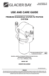
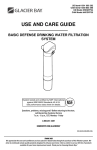
Item #1001 104 017
Model #HDGASS4
USE AND CARE GUIDE
AUTOMATIC HOUSEHOLD WATER FILTRATION
SYSTEM
HDGASS4 is tested and certified by NSF
International against NSF/ANSI Standards 42
for structural integrity and materials safety only.
NSF
®
COMPONENT
Filter screen is tested and certified by NSF
International against NSF/ANSI Standards 42
for materials safety only.
NSF
®
COMPONENT
Questions, problems, missing parts? Before returning to the store,
call Glacier Bay Customer Service
7 a.m. - 6 p.m., CST, Monday - Friday
1- 800800- 247247 -1087
HOMEDEPOT.COM/GLACIER
HOMEDEPOT.COM/GLACIERBAY
/GLACIERBAY
201-8401468 (REV 00)
THANK YOU
We appreciate the trust and confidence you have placed in Glacier Bay through the purchase of this filtration system.
We strive to continually create quality products designed to enhance your home. Visit us online to see our full line of
products available for your home improvement needs. Thank you for choosing Glacier Bay!
Table of Contents
Safety Information .................................2
Warranty .................................................3
Glacier Bay Water Filtration Systems Warranty..................................................... 3
Pre-Installation ......................................3
Pre-Installation Inspection ......................... 3
Specifications ............................................ 3
Installation Location ................................... 4
Dimensions ................................................ 4
How the Filtration System Works ............... 4
Filtration System Orientation ..................... 5
Reversing the Faceplate/Display................ 5
Mounting Bracket ....................................... 6
Tools Required ........................................... 7
Package Contents ...................................... 7
Installation Requirements ....................8
Plumbing Codes ......................................... 8
Air Gap Requirements ................................ 8
Connecting the Valve to the Drain .............. 8
Valve Drain Requirements .......................... 8
Grounding Information (for Installations
on a Metal Pipe) ......................................... 9
Installation ............................................. 9
Programming the Electronic Controller11
Powering Up ............................................. 11
Manually Starting a Sediment Flush ........ 11
Normal Operation ..................................... 11
LCD Backlight........................................... 11
Setting the Number of Days between Automatic
Sediment Flushes .................................... 12
Time of Day when Flush occurs ............... 12
Low Battery Indication/
Battery Replacement ............................... 12
Maintenance ........................................ 13
Cleaning the Filter screen ........................ 13
Troubleshooting .................................. 14
Disassembling the Solenoid..................... 15
DIsassembling the Valve .......................... 15
Replacement Parts ............................. 16
Safety Information
CAUTION:: Keep solvents and sprays away from
the clear sump housing material. Surface cracking
and failure can result.
Read all instructions before installing and using your
water filtration system. Follow all steps exactly to
correctly install. Reading this manual will also help
you to get all the benefits from the filtration system.
NOTICE:: This filtration system works on water pressures of 30
psi (minimum) to 100 psi (maximum). If your house water
pressure is over the maximum, install a pressure reducing valve
in the water supply pipe to the filtration system.
This filter must only be installed vertically, with the
head up and the sump down. It will not operate
properly if installed horizontally or at an angle.
NOTICE:: All plumbing codes must be completed in
accordance with national, state, and local plumbing codes. Local
code information can be obtained at your local public works
department.
All plumbing must be completed in accordance with
national, state and local plumbing codes. Local code
information can be obtained at your local public
works department. Consult with your licensed
plumber.
NOTICE:: European Directive 2002/96/EC requires all electrical
and electronic equipment to be disposed of according to Waste
Electrical and Electronic Equipment (WEEE) requirements. This
directive or similar laws are in place nationally and can vary
from region to region. Please refer to your state and local laws
for proper disposal of this equipment.
Use only lead-free solder and flux for all sweatsolder connections, as required by federal codes.
WARNING:: Do not use with water that is
microbiologically unsafe or of unknown quality
without adequate disinfection before or after the
system.
NOTICE:: In the state of Massachusetts: The Commonwealth
of Massachusetts plumbing code 248-CMR shall be adhered to.
A licensed plumber shall be used for this installation.
CAUTION:: Do not install the filtration system
outside, or in extreme hot or cold temperatures.
Avoid installing in direct sunlight. Excessive sun heat
may cause distortion or other damage to nonmetallic parts. Temperature of the water supply to
the filtration system must be between 40°F and
120°F. Do not install on a hot water line.
2
Warranty
GLACIER BAY WATER FILTRATION SYSTEMS - WARRANTY
Glacier Bay Water Filtration Systems are manufactured under the highest standards of quality and workmanship.
Glacier Bay Water Filtration Systems warrants to the original purchaser that this system will be leak and drip free
during normal domestic use for a period of one (1) year from date of purchase. If this system should ever develop a
leak or drip Glacier Bay Water Filtration Systems will free of charge provide the parts necessary to put the system
back in good working condition. A replacement for any defective part will be supplied free of charge for installation
by the purchaser. Defects or damage caused by use of other than authorized parts are not covered by this warranty.
This warranty shall be effective from date of purchase as shown on purchaser’s receipt. Glacier Bay Water Filtration
Systems shall be installed per the manufacturer’s installation instructions and specifications. Some states do not
allow limitations on how long a warranty lasts, so the above limitation may not apply to you. This warranty is valid
for the original purchaser only and excludes industrial, commercial, or business use of the product, product misuse,
and product damage due to installation error, whether performed by a contractor, service company, or yourself.
Glacier Bay Water Filtration Systems will not be responsible for labor charges or for damage incurred during
installation, repair or replacement, nor for incidental or consequential damages. Some states, provinces and nations
do not allow the exclusion or limitation of incidental or consequential damages, so the above exclusions or
limitations may not apply to you. Glacier Bay Water Filtration Systems will advise you of the procedure to follow in
making warranty claims.
Simply write to Glacier Bay Water Filtration Systems at the address below. Explain the defect and include proof of
purchase and you name, address and telephone number or you can also call us at 1-800-247-1087.
U.S.A
Canada
Glacier Bay Water Filtration Systems
Glacier Bay Water Filtration Systems
2455 Paces Ferry Road, N.W.
900-1 Concorde Gate
Atlanta, GA 30339-4024
Toronto, ON M3C 4H9
Pre-Installation
PREPRE-INSTALLATION INSPECTION
INSPECTION
Thoroughly check the water filtration system for possible shipping damaged and parts loss. Also inspect and note
any damage to the shipping carton. Remove and discard (or recycle) all packing materials. To avoid loss of small
parts, we suggest you keep them in the parts bag until you are ready to use them.
SPECIFICATIONS
Supply Water Pressure Min. - Max.
Supply Water Temperature Min. - Max.
Rated Service Flow @ 60 psi (414 kPa)
Inlet - Outlet
30 - 100 psi (207 - 689 kPa)
40 - 100°F (5 - 38°C)
35 gallons per minute (132 liters per minute)
1 in. NPT
3
HOMEDEPOT.COM/GLACIERBAY
Please contact 1-800-247-1087 for further assistance.
Pre-Installation (continued)
INSTALLATION
INSTALLATION LOCATION
To filter sediment from all household water, install the filter system on the household’s main incoming water pipe.
Install upstream from the water softener (if any), the water heater, and all inside faucets.
Cold Water
to House
Untreated Water to
Outside Faucets
Hot Water
to House
City Water Supply
Pressure
Tank OR
Automatic
Household Water
Filtration System
Water Water
Heater Softener
Well Water Supply
Well
Pump
DIMENSIONS
15 in.
10 in.
4-1/8 in.
5-1/4 in.
HOW THE FILTRATION SYSTEM WORKS
This filtration system is designed to be plumbed into a home’s incoming water supply pipe, where it will capture
sediment from the water and periodically flush them down the drain.
This product is designed to reduce sand, grit, debris, pipe scale and other loose matter. On water supplies that
contain sticky sediment including mud, silt and clay, you may have to remove the sump and clean the screen
frequently.
The unit has an electronic control that counts down the days until the next automatic flush of collected sediment.
The number of days is programmable. The electronic controller runs on a 9 volt battery. The controller will indicate
when the battery needs to be replaced. An optional AC power adaptor (P/N 7302835) may also be purchased to
eliminate the need for batteries.
Three sizes of filter mesh are available. A 60 micron filter is included with the unit, and optional 100 or 150 micron
filters can also be purchased (see the Spare Parts List at the end of this manual).
4
Pre-Installation (continued)
FILTRATION SYSTEM ORIENTATION
ORIENTATION
To operate properly, the system must
be installed with the sump pointed
straight down. When possible, install
the system on a horizontal section of
the household’s main incoming water
pipe. If the water pipe runs vertically
where you want to install the filter, buy
90° pipe elbows and plumb a detour.
Allow enough space under the system
(6 in. minimum) to remove the sump (to
clean or replace the filter screen).
Allow enough space above the system
to remove the top cover (to change
batteries, etc.).
10 in.
min.
OUT
IN
House Water
Supply Pipe
Sump
Pointed
Straight
Down
6 in.
min.
REVERSING THE FACEPLATE/DISPLAY
FACEPLATE/DISPLAY
The system must be installed with the water flowing into
the side marked IN. Remove the unit’s top cover and
observe the IN and OUT markings. Depending on the
direction of water flow and the viewing angle, the
faceplate may need to be reversed so that it does not
end up against a wall or other obstruction. This can be
done either before or after the filter is installed on the
plumbing:
1.
Remove the top cover by sliding it upward.
2.
With a Phillips screwdriver, remove the screws
holding the faceplate assembly to the filter head.
3.
Lift the faceplate assembly up and turn it around
180°, taking care not to pull on the wires between
the electronic control board and the valve
solenoid.
4.
Lower the faceplate assembly into place on the
opposite side of the head and reinstall the two
screws.
5.
Slide the top cover back on and push it down to
snap into place.
5
HOMEDEPOT.COM/GLACIERBAY
Please contact 1-800-247-1087 for further assistance.
Pre-Installation (continued)
MOUNTING BRACKET
A metal bracket (B) is included with the system to
support the assembled system and plumbing when
necessary. It may be mounted to a wall or wall framing
member with two screws (included).
B
E
D
6
Pre-Installation (continued)
TOOLS REQUIRED
Phillips
screwdriver
Pliers
Adjustable jaw
wrench
Sealant
tape
PACKAGE CONTENTS
A
B
Part
E
C
F
D
G
Description
Quantity
A
Filtration System
1
B
Mounting bracket with two screws
2
C
Drain hose
1
D
Adapters
2
E
Clips
2
F
9V Battery
1
G
Hose clamp
1
7
HOMEDEPOT.COM/GLACIERBAY
Please contact 1-800-247-1087 for further assistance.
Installation Requirements
PLUMBING CODES
All plumbing must be completed in accordance with national, state, and local plumbing codes.
NOTICE: In the state of Massachusetts, the Commonwealth of Massachusetts plumbing code 248-CMR shall be
adhered to. A licensed plumber shall be used for this installation.
AIR GAP
GAP REQUIREMENTS
A drain is needed for sediment flush discharge water. A floor drain, close to the filter, is preferred. A laundry tub,
standpipe, etc. are other drain options. The valve drain hose must be secured in place, since drain water will be
spraying from the end of the hose at a high rate during flush cycles. Leave an air gap of 1-1/2 in. between the end of
the hose and the drain. This gap is needed to prevent backflow of sewer water into the filter. Do not put the end of
the drain hose into the drain.
CONNECTING THE VALVE
VALVE TO THE DRAIN
IMPORTANT:
Flow rate to drain can exceed 9 gpm
at higher pressure. Be sure to secure
both ends of drain hose properly and test.
Drain
Fitting
IMPORTANT:
To prevent drain hose from
detaching from system during a flush
do not kink, crush or obstruct the hose.
Hose
Clamp
Valve Drain
Hose
To drain point other
than floor drain.
Support tubing in
place as needed.
1-1/2 in.
air gap
Aim end of drain
hose toward center
of drain. Tie or wire
tubing in place.
Drain grate
with 1 in. dia.
hole in center
1-1/2 in.
air gap
LAUNDRY TUB
1-1/2 in.
air gap
STANDPIPE
VALVE DRAIN REQUIREMENTS
REQUIREMENTS
Using the flexible drain hose (included), measure and cut to the length needed.
□
□
□
□
Avoid a drain hose that runs longer than 10 ft. Make the valve drain line as short and direct as possible.
If possible, avoid elevating the drain hose. This could reduce the effectiveness of the flush cycle, especially in a
low pressure application.
The drain must be capable of handling a flow of 5 to 10 gallons per minute, depending on the home’s water
pressure.
The drain must be capable of handling the sediment being flushed from the filter.
8
Installation Requirements (continued)
GROUNDING INFORMATION
INFORMATION (FOR INSTALLATIONS
INSTALLATIONS ON A METAL PIPE)
The house main incoming water pipe is often used to ground electrical outlets in the home. Grounding protects you
from electrical shock. Installing the filter may break this ground. To restore it, buy and install a #4 copper wire
across the filter, tightly clamped at both ends, as shown below.
Ground Wire
(not included)
Clamp
(2 - not
included)
Installation
1
Attaching the adaptors and
clips to the fitter
2
□ Insert the adaptors (D) into the holes on each side of
the filter head.
□ Secure in place with the clips (E). Ensure all three
tabs of the clips go through the matching holes and
fully in the channels on the adaptor (D).
E
D
Connecting the water supply
lines
IMPORTANT:: Do not solder the metal plumbing
while attached to plastic installation adaptors. Solder
heat will damage the adaptors.
□ Seal the inlet (1) and outlet (2) threads of the
filter adaptors with several wraps of sealant
tape.
□ Connect the water supply lines to the inlet (1)
and outlet (2) using 1 in. female NPT threaded
adaptors (not included). Use caution to avoid
cross-threading the adaptors.
E
2
D
1
CORRECT ASSEMBLY
Clip
Outside diameter
of Filtration
System Head
Outside diameter
of clip channel
on Adaptor
9
HOMEDEPOT.COM/GLACIERBAY
Please contact 1-800-247-1087 for further assistance.
Installation (continued)
3
4
Installing the drain hose
□ Measure, cut to needed length, and connect the 3/8
in. drain line (provided) to the filter’s valve drain
fitting. Use a hose clamp to hold the hose in place.
See “Connecting the Valve to the Drain” on page 8
for a complete diagram of this procedure.
□ Run the drain hose or copper tubing to the floor
drain. Secure the drain hose. This will prevent the
drain line from “whipping” during sediment flush
cycles. See the “Air Gap Requirements" section on
page 8.
5
Checking for leaks
□ With the installation steps completed, fully
open the home’s main water supply valve.
□ Check for leaks at all the plumbing
connections you made.
□ Make sure the electronics are completely dry
before powering the unit up (as described in
the next section).
Installing the battery
Top Cover
□ Take the included 9V battery out of its plastic wrap.
□ Remove the top cover by sliding it upward.
□ Snap the battery connector onto both terminals of
the 9V battery.
□ Place the connected battery into the clip provided
for it directly above the IN port.
□ Slide the top cover back on and push it down to
snap into place.
6
Battery Connector
9V Battery
Clip
Optional: Using an AC adaptor
(not included)
An optional AC adaptor (P/N 7302835) is available to
supply 9V DC power to the electronic control instead of
using a 9V battery. This adaptor has 5 ft. of wire. One
end plugs into a household 120V AC, 60 Hz. outlet and
the other end plugs into the back of the electronic
control board. See the Replacement Parts section on
page 16 for ordering information.
Top Cover
Optional
AC Adaptor
IMPORTANT:: Do not use any AC adaptor other
than the EcoPure P/N 7302835 with this filter.
□ Remove the top cover by sliding it upward.
□ Remove any previously installed 9V battery
(disconnect it from the battery connector and lift it
out of the clip above the IN port).
□ Locate the small round plug on one end of the AC
adaptor cable and insert this into the connector on
back of the electronic control board.
□ Plug the other end of the AC adaptor into a 120V, 60
Hz household electric socket.
□ Before replacing the cover, feed the wire through
the small slot above the IN port.
□ Slide the top cover back on, making sure not to
pinch any wires, and push it down to snap into
place.
10
Feed Wire
through Slot
Plug into
Connector on
Electronic
Control Board
Programming the Electronic Controller
POWERING UP
When the controller is powered up (by installing the battery or plugging in the optional AC adaptor), the display will
briefly show the software version (example “1.0”), then the number of days until the next automatic sediment flush.
MANUALLY STARTING
STARTING A SEDIMENT FLUSH
FLUSH
After all installation steps have been completed, initiate
a manual sediment flush as follows:
1.
Press the CLEAN NOW button and hold it for at
least 2 seconds. When the 2-digit display changes
to show moving dashes release the CLEAN NOW
button.
2.
Check the drain hose to ensure a secure
connection.
3.
The sediment flush sequence takes about 30
seconds to complete. The flow of water to the
drain will start and stop several times.
4.
Once the sediment flush has been completed, the
2-digit display will change to show the number of
days until the next automatic flush (or if the
automatic flush feature has been turned off it will
show “- -”).
Moving dashes
indicate sediment
flush is taking place
The filter can be manually activated to flush sediment at
any time, regardless of whether or not it is set to flush
automatically.
NORMAL
NORMAL OPERATION
During normal operation, the LED will momentarily blink green every 8 seconds and the 2-digit display (LCD) will
show the number of days remaining until the next automatic sediment flush. Momentarily pressing the PROGRAM
button shows the setting for the number of days between flushes.
LCD BACKLIGHT
2-Digit LCD Display
(when unit is in normal
operation, LCD shows
number of days until
next automatic
sediment flush)
The 2-digit display has a backlight that goes on
whenever a button is pressed. It goes off again after 10
seconds if no more buttons have been pressed (to
conserve battery life). Momentarily press either the
PROGRAM or CLEAN NOW button to turn on the
backlight.
LED (see table below)
LED Color
Green
Amber
Red
None
State of LED
Blinks every 8 seconds
On steady
Blinks every 8 seconds
Completely off
11
Shows when…
The unit is in normal operation.
You are programming the controller.
The battery is low.
The battery is dead or disconnected.
HOMEDEPOT.COM/GLACIERBAY
Please contact 1-800-247-1087 for further assistance.
Programming the Electronic Controller (continued)
SETTING THE NUMBER OF
OF DAYS
DAYS BETWEEN AUTOMATIC SEDIMENT FLUSHES
FLUSHES
The filter controller is shipped with a default value of 7
days between automatic sediment flushes. To change
the number of days (between 1 and 30) or to turn this
feature off:
1.
Press the PROGRAM button and hold it for at least
2 seconds. When the LED turns on steadily with an
amber color, quickly release the PROGRAM button.
2.
While the amber LED is on (it turns off after 10
seconds of button inactivity), repeatedly press the
PROGRAM button until the desired number of days
shows in the display. Each press increases the
number of days by 1. When the number passes 30,
it returns to zero, indicated by “- -”, and counts up
from 1 again.
3.
Setting the number of days to “- -” (zero) turns off
the automatic flush feature.
4.
When the desired number of days shows in the
display, wait 10 seconds (press no more buttons)
for the amber LED to go off. The new number of
days is programmed. This new setting will remain
after a battery change or power loss.
Two dashes
(not moving in the
display indicate
automatic flush is
turned off)
TIME OF DAY WHEN FLUSH
FLUSH OCCURS
The time of day when the automatic sediment flush occurs is the same time of day as when the most recent of the
following was done:
□
□
□
The filter was powered up (battery installed or replaced, optional AC adaptor plugged in).
The number of days was set.
A manual flush was initiated.
If a different time of day is desired for automatic flush, initiate a manual flush at the desired time of day.
LOW BATTERY INDICATION/BATTERY
INDICATION/BATTERY REPLACEMENT
REPLACEMENT
If the LED is blinking red every 8 seconds (and the 2- digit
display shows “EE“), then the battery needs to be
replaced.
1.
Remove the top cover from the filter by sliding it
upward.
2.
Locate the old battery and unsnap it from the
battery connector. Dispose of (recycle) the old
battery properly.
3.
Take a new 9-volt battery and snap the battery
connector onto both terminals.
4.
Place the connected battery into the clip provided
for it directly above the IN port.
5.
Slide the top cover back onto the filter and push it
down to snap into place.
“EE” in the display
indicates battery is low
LED blinking red every
8 seconds indicates
battery is low
No reprogramming of the controller is necessary after
battery replacement or a power outage.
12
Maintenance
CLEANING
CLEANING THE FILTER SCREEN
SCREEN
It may be necessary to manually clean the filter screen
from time to time. On water supplies that contain sticky
sediment including mud, silt and clay, you may have to
remove the sump and clean the screen frequently. Also, if
the filter has not been automatically flushing for any
reason, such as a dead battery, a larger amount of
sediment than normal may have accumulated in the
sump. In this case it is recommended that the sump and
filter be cleaned manually (an excess amount of sediment
could plug the valve).
1.
Before shutting off the water supply (as directed in
Step 2), fill a bucket full or sink full of water to use
for cleaning the filter screen.
2.
Shut off the main house water supply valve
upstream from the filter.
3.
Open a cold water faucet in the house (downstream
from the filter) to depressurize the system. Then
close this faucet again.
4.
Remove the sump by turning it to the left to
unscrew it from the filter head. Be prepared for
water to drip out of the filter head when the sump is
removed.
5.
Remove the filter screen assembly by pulling it
down out of the filter head.
6.
Using the water you saved in Step 1, wash the filter
screen assembly. If necessary, gently scrub the
filter mesh with a soft brush to remove material
from the pores.
7.
The drain straw may have come out of the filter
head when the sump and filter screen were
removed. If so, reinsert it into the small hole at the
center of the head assembly.
8.
Make sure the small O-ring is in place on the filter
screen assembly. Make sure that no sediment
particles are on the O-ring or the corresponding
sealing area in the head. Slide the filter screen over
the drain straw and into the corresponding hole at
the center of the filter head. Push it in to engage the
O-ring seal.
9.
Make sure the large O-ring is in place on the sump. Make sure no sediment particles are on the O-ring, sump
threads or corresponding threads in the filter head. Slide the sump over the filter screen and screw it into the
filter head to seal. Do not overtighten.
10.
Open a cold water faucet in the house downstream from the filter.
11.
Turn the main house water supply back on.
12.
Close the faucet that you opened in Step 10 after air has been expelled from the system and water is flowing
smoothly with no spurting.
13.
Check that there is no water leaking from the sump threads. Tighten the sump if necessary.
13
HOMEDEPOT.COM/GLACIERBAY
Please contact 1-800-247-1087 for further assistance.
Troubleshooting
Problem
Possible Cause
Solution
Sediment flush does not
initiate.
The battery is dead.
Replace the battery.
There is a low or no water flow
through the filter.
The filter is plugged.
Manually clean filter screen. It may be
necessary to reduce the number of days
between automatic sediment flushes.
Sediment does not leave the
sump during the sediment
flush cycle.
The valve is plugged.
Manually clean the filter screen. After water
has been turned back on, initiate another clean
cycle (hold the CLEAN NOW button for 2
seconds). Repeat if necessary. If caused by too
great a volume of sediment, it may be
necessary to reduce the number of days
between automatic sediment flushes. If this
does not clear the plugged valve, it may be
necessary to disassemble the valve and clean
manually as explained in the Disassembling
the Valve section.
The drain hose is plugged.
Disconnect the drain hose, remove the
obstruction, and reconnect.
There is insufficient water
pressure.
Make sure the water pressure requirement of
30 psi minimum is met. Shorten the drain line.
Misapplication of the
product.
See the “How the Automatic Sediment Filter
Works” section of this manual.
The solenoid seat is dirty.
Initiate several clean cycles. If the leak
continues, remove the valve solenoid and
clean the seat area. See the “Disassembling
the Solenoid” section of this manual.
The valve is plugged or the
valve seat is dirty.
Manually clean the filter screen. After water
has been turned back on, initiate another clean
cycle (hold the CLEAN NOW button for 2
seconds). Repeat if necessary. If caused by too
great a volume of sediment, it may be
necessary to reduce the number of days
between automatic sediment flushes. If this
does not clear the plugged valve, it may be
necessary to disassemble the valve and clean
manually. See the “Disassembling the Valve”
section on page 15.
There is a continuous leak to
the drain.
14
Troubleshooting (continued)
DISASSEMBLING THE SOLENOID
SOLENOID
(See the Exploded View drawing in the Replacement Parts section on page 16.)
If the Troubleshooting table indicates that the solenoid seat requires cleaning, use the following procedure:
1.
Before shutting off the water supply (as directed in Step 2), fill a bucket or sink full of water to use for
cleaning.
2.
Shut off the main house water supply valve upstream from the filter.
3.
Open a cold water faucet in the house (downstream from the filter) to depressurize the system. Close the
faucet again.
4.
Remove the solenoid by unscrewing it from the top of the valve using a flat screwdriver.
5.
Using the water you saved in Step 1, clean the solenoid seat, plunger, and hole.
6.
Make sure the O-ring is in place and reinstall the solenoid, being careful not to cross-thread.
7.
Open a cold water faucet downstream from the filter.
8.
Turn the main house water supply back on.
9.
Close the faucet that you opened in Step 7 after air has been expelled from the system.
10.
Check that there is no water leaking from the solenoid thread area. Tighten the solenoid if necessary.
DISASSEMBLING THE VALVE
VALVE
(See the Exploded View drawing in the Replacement Parts section on page 16.)
If the Troubleshooting table indicates that the valve requires cleaning, use the following procedure:
1.
Before shutting off the water supply (as directed in Step 2), fill a bucket or sink full of water to use for
cleaning.
2.
Shut off the main house water supply valve upstream from the filter.
3.
Open a cold water faucet in the house (downstream from the filter) to depressurize the system. Close the
faucet again.
4.
Remove the six screws from the top of the valve and lift off the valve cover.
5.
Using the water you saved in Step 1, clean the diaphragm and seat area of the valve body.
6.
Make sure the two small holes in the valve body under the diaphragm are not plugged.
7.
Reassemble the valve, making sure the diaphragm is right side up (small knob at center points up) and the
other components are properly placed.
8.
Open a cold water faucet downstream from the filter.
9.
Turn the main house water supply back on.
10.
Close the faucet that you opened in Step 8 after air has been expelled from the system.
11.
Check that there is no water leaking from the valve sealing area. Tighten the screws if necessary.
15
HOMEDEPOT.COM/GLACIERBAY
Please contact 1-800-247-1087 for further assistance.
Replacement Parts
1
5
2
4
19
17
3
6
7
26
25
20
8
27
18
9
11
12
13
15
10
24
21
23
22
14
16
Key
No.
Part No.
Description
Key
No.
Part No.
Description
1
2
7298442
Top Cover
16
1073-27-HA
Head Assembly
7295177
Electronic Control Board (PWA)
17
7300312
O-Ring, Sump
3
7298434
Faceplate (order decal below)
18
7298395
Sump
4
107-8402032
Decal, Faceplate
19
7300304
Drain Straw
5
7300346
Screw, 6-19 x 1/2" (2 req.)
7298808
Filter Screen Assembly, 60 Micron
(includes Key No. 21)
6
7301596
Solenoid
7298816
Filter Screen Assembly, 100 Micron
(includes Key No. 21)**
7
7301758
O-Ring, Solenoid
7298824
Filter Screen Assembly, 150 Micron
(includes Key No. 21)
8
7300338
Screw, 10-16 x 1-1/4" (6 req.)
21
7011086
O-Ring, Filter
9
7298426
Valve Cover
22
7139999
Drain Hose, 20 ft.
10
7301520
Spring
23
0900431
Clamp, Drain Hose
11
7301685
Retainer, Spring
24
1073-27-03
Bracket, Mounting
12
7301512
Diaphragm
25
9006053
Screw, 10-16 AB (2 req.)
13
7298418
Valve Body
26
7302835
AC Power Adaptor**
14
7300320
O-Ring, Valve (2 req.)
27
-
Battery, 9 Volt, Standard
15
7272658
Check Valve
■
201-8401468
Owner’s Manual
■ Not illustrated
20
* Optional – not included with Automatic Household Water Filtration System
To order replacement parts call 1-800-247-1087, 7 a.m. - 6 p.m., CST, Monday - Friday
16
Questions, problems, missing parts? Before returning to the store,
call Glacier Bay Customer Service
7 a.m.-6 p.m., CST, Monday-Friday
1- 800800- 247247-1087
HOMEDEPOT.COM
HOMEDEPOT.COM/GLACIER
.COM /GLACIERBAY
/GLACIERBAY
Retain this manual for future use.
Manufactured by
Ecodyne Water Systems
1890 Woodlane Drive
Woodbury, MN 55125