1
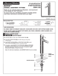
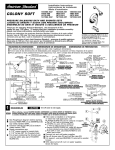
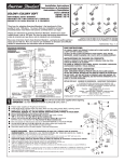
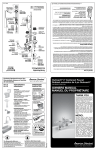
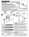
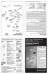
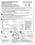
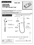
Installation
Instructions
R701
IN-WALL
ON/OFF VOLUME
CONTROL VALVE
1/2" INLET/OUTLET
Thank you for selecting American-Standard...the
benchmark of fine quality for over 100 years.
Certified to comply with ANSI A112.18.1M
ASSE 1016
To ensure that your installation proceeds smoothly--please
read these instructions carefully before you begin.
M 0 3 4 8 0 3 R e v. 1 . 2
Recommended Tools
Flat Blade Screwdriver
Phillips Screwdriver
Teflon Tape
Adjustable Wrench
Pipe Wrench
ROUGHING-IN DIMENSIONS
1/2" NPT
60mm±13mm
(2-3/8 ± 1/2)
1/2" NPT
FEMALE
OUTLET
52mm
(2-1/8)
DIA. HOLE
29mm
(1-1/8)
51mm
(2)
UNION INLET
1/2" - 14 NPT
OR
5/8" O.D.
COPPER
SWEAT
FINISHED
WALL
47.5mm
(1-7/8) MIN.
73mm
(2-7/8) MAX.
FINISHED
WALL
1
ROUGHING-IN FITTING
CAUTION
Turn off hot and cold water
supplies before beginning.
OUTLET PIPING
Prepare water supply per "Roughing-in Dimensions."
CROSS BRACE
Slip COUPLING NUT (1) over UNION NIPPLE (2). Thread
UNION NIPPLE (2) to SUPPLY PIPE (3). Use appropriate sealant
on all threaded connections.
SECURE PIPING
For Sweat Connection: Slip COUPLING NUT over 5/8'' O.D.SUPPLY
TUBE (4) and solder TUBE (4) into UNION NIPPLE (2).
Install VALVE (5) at indicated height and depth (Optional). Note
MAX WALL marking on PLASTER GUARD (6) for the finished wall.
Connect water supply to VALVE (5) inlet. Tighten COUPLING
NUT (1) firmly.
Add cross braces to wall structure and secure piping.
Secure VALVE BODY (5) to cross brass of wall structure.
Connect outlet piping to valve outlet. Cap off outlet if necessary.
TEST INSTALLED VALVE
"MAX WALL"
M
A X
W
L
6
A
L
2
5
2
Remove PLASTER GUARD (6). (Do not discard.)
Turn VALVE BODY (5) into OFF position.
1
Turn on water supplies, open VALVE BODY (5) and check all
connections for leaks.
Operate VALVE BODY (5) to flush water lines thoroughly.
Turn VALVE BODY (5) OFF.
Replace PLASTER GUARD (6)
3
3
4
FINISHING INSTALLATION
Finish wall construction. NOTE: Apply wall finish as close as
possible to the PLASTER GUARD (6).
4
SERVICE
To change direction of handle rotation,
proceed as follows:
Turn valve to OFF position.
Remove SPRING CLIP.
Lift STOP WASHER, turn 90° and replace.
Replace SPRING CLIP.
STOP
WASHER
SPRING
CLIP
90°
If valve drips, operate several times from
OFF to ON position. Do not force - valve turns only 90°.
Plastic SCREEN in CARTRIDGE may accumulate
dirt causing reduced water flow. To clean, first
turn off hot and cold water supplies, then:
Thoroughly rinse plastic SCREEN at
base of CARTRIDGE.
Replace CARTRIDGE until flange is
tight against valve body.
Turn valves OFF.
CARTRIDGE
SCREEN
M 0 3 4 8 0 3 R e v. 1 . 2
IN-WALL
ON/OFF VOLUME
CONTROL VALVE
1/2" INLET/OUTLET
MODEL NUMBER
R701
028610-0070A
CARTRIDGE
M
A X
W
A
L
L
012315-0070A
GROUND JOINT INLET
HOT LINE FOR HELP
For toll-free information and answers to your questions, call:
1-800-442-1902
Weekdays 8:00 a.m. to 6:00 p.m. EST
IN CANADA 1-800-387-0369 (TORONTO 1-905-306-1093)
Weekdays 8:00 a.m. to 7:00 p.m. EST
IN MEXICO 01-800-839-12-00
Product names listed herein are trademarks of American Standard Inc.
© AS America, Inc. 2008
M 0 3 4 8 0 3 R e v. 1 . 2