1
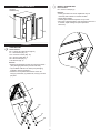
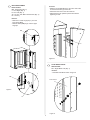
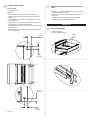
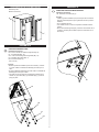
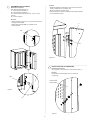
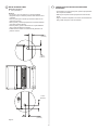
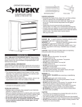
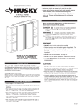
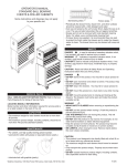
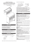
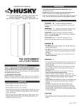
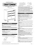
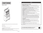
OPERATOR’S MANUAL
2-DOOR BASE CABINET
MODEL # 27BC201BP-THD
Ball bearing slides
Friction slides
PAINTED SURFACES:
• Periodically the drawer fronts, drawer trim, and other surfaces
should be cleaned with a mild detergent and water.
• Auto wax will preserve the unit’s luster finish. Apply the wax as to a car. The wax will also help protect the unit against scratches.
• Grease and oil can be removed with most standard
cleaning fluids. For safety, use a nonflammable cleaning fluid.
• If drawer liners are supplied, it is recommended they are used
to protect the finish inside the drawers and to make the drawers
easier to clean. The drawer liners may be cleaned
with soap and water.
SAFETY
DANGER
is used to indicate a hazardous situation which,
if not avoided, will result in serious injury or death.
WARNING
indicates a hazardous situation which,
if not avoided, could result in serious injury or death.
CAUTION is used to indicate a hazardous situation which, if not
avoided, may result in minor injury, moderate injury, or property
damage.
CAUTION: Read and follow all Safety Rules and Operating
Instructions before first use of this product.
SERVICE PARTS
CALL 1-866-440-3170 FOR SERVICE PARTS. Please provide
the Model Number when calling. To expand your garage storage
project, please visit www.homedepot.com/garagestorage for additional product options.
LOCATING MODEL # INFORMATION
Model numbers and other information required for service parts is
located on a white label on the upper right hand corner of the unit.
CAPACITIES
• The maximum load capacity for each shelf is 30 lbs. evenly
distributed. The maximum load capacity per work surface is 500
lbs. evenly distributed.
• Empty weight of the unit is 69 lbs.
• The maximum product weight, including contents in the drawers/shelves and on the work surface, should be no more than
629 lbs.
MAINTENANCE
• Lubricate lock with graphite, (yearly).
STAINLESS SURFACES:
• Stainless steel can discolor when exposed to pool chemicals,
saltwater or cleaners with bleach.
• Keep your stainless looking new by cleaning with a good quality
all-in-one stainless steel cleaner polish monthly. Frequent cleaning will remove surface contamination that could lead to rust.
• Do not clean with steel wool or other abrasive pads.
• Do not use cleaners not specifically intended for stainless
steel on stainless surfaces (this includes glass, tile and
counter cleaners).
DANGER
• DO NOT stand on this product. You may fall
or cause product to tip.
• DO NOT open more than one drawer. The product
may become unstable and tip.
• DO NOT step in the drawers. You may fall
or cause product to tip.
• DO NOT mount this product on a truck bed
or any other moving object.
• DO NOT move the product prior to closing
and locking all the drawers. The drawers could come open
and make the product unstable and tip.
WARNING
• WEAR SAFETY GLASSES when removing or repositioning
the slides.
• DO NOT pull the unit, push it when moving
• USE THE BRAKES when not moving this product. This will prevent the product from rolling.
• DO NOT alter this product in any manner. For example, do not weld external lockbars or attach electrical equipment.
• Keep the product on level surfaces. The product may become unstable and tip if stored or moved on an uneven surface.
• BE CAREFUL when closing the cover. Remove hands before the cover closes completely.
CAUTION
• This product is not designed to be directly lifted with a fork lift, or to be towed with any mechanical devices.
• The maximum weight for each drawer should never be exceeded.
• Only transport this product empty. Properly secure when transporting.
• DO NOT exceed maximum product weight, including contents. See Capacities for more information.
F1775
HARDWARE
JJ - Magnet (Qty: 2)
TOOLS REQUIRED:
1/2in wrench (2)
OPTIONAL TOOLS:
Screwdriver
Flathead
7/16in Open end wrench
KK - Right Hinge (Qty: 2)
HARDWARE INCLUDED:
LL - Left Hinge (Qty: 2)
AA - 1/4-20 x 3/4in Button
Head Screw (Qty: 8)
BB - #10-24 x 1/2in Carriage
Bolt (Qty: 8)
MM - Hinge Plate (Qty: 4)
CC - 3/16 Washer (Qty: 8)
DD - #10-24 Keps Nut (Qty: 8)
NN - Single Bitted Lock
(Qty: 1)
EE - 5/16-18 Hex Head Screw (Qty: 16)
FF - 5/16 Washer (Qty: 16)
PP - 5/32in Hex Key (Qty: 1)
GG - 5/16-18 Hex Locknut (Qty: 16)
RR - Mount Plate (Qty: 4)
HH - Screw leveler (Qty: 4)
2
INSTALL LEVELING FEET
Items Needed:
HH - Screw Leveler(Qty:4)
CARTON CONTENTS
Literature
Hardware bag
Process:
• Install (4) levelers HH. Some adjustmnet may be
necessary after cabinet is in desired location.
• Stand cabinet upright.
• Carefully place stainless top back on top of unit.
• Move unit to desired position and check that unit is level.
If needed, adjust leveling feet (See Operations
Section D).
A
C
B
ASSEMBLY
LEVELING FEET
Items Needed:
EE - 5/16-18 Hex Head Screw (Qty:16)
FF - 5/16 Washer (Qty: 16)
GG - 5/16 Hex Locknut (Qty: 16)
HH - Screw Leveler (Qty: 4)
RR - Mount Plate (Qty: 4)
1/2in Wrench (Qty: 2)
Process:
• Remove the stainless top from the unit and set aside.
(Use packaging material to prevent scratches.)
• Lay the Base Cabinet on its back. (Use packaging
material to prevent scratches.)
• Attach the mount plates RR to bottom of the unit
using (4) screws EE, (4) washers FF, and (4) nuts GG
per plate.
HH
EE
RR
FF
GG
3
DOOR CONSTRUCTION
Items Needed:
C - Door Right (Qty: 1)
B - Door Left (Qty: 1)
LL - Left Hinge (Qty: 2)
KK - Right Hinge (Qty: 2)
BB - #10-24 x 1/2in Carriage Bolt (Qty: 8)
CC - 3/16in Washer (Qty: 8)
DD - 10-24 Keps Nut (Qty: 8)
Step 3 Result
Figure 3
UNIT HINGE ATTACHMENT
Items Needed:
MM - Hinge Plate (Qty: 2)
AA - 1/4-20 x 3/4in Button Head Screw (Qty: 4)
PP - Hex Key
Process:
• Attach the Hinges LL and KK to the Doors B and C using
(4) EE, (4) FF and (4) GG.
• Wrench Tighten.
• Repeat for other door.
Process:
• Place (1) hinge plate MM on each side of the unit at the
bottom. Slide plate through the slot and secure each with
(2) screws AA.
Note: The hinges for both doors MUST be mounted so the
hinge pin points UP at the TOP of the door and DOWN at
the BOTTOM of the door. (See Figure 3.1)
BB
CC
DD
LL
MM
B
AA
KK
Figure 3.1
Figure 4
4
DOOR ATTACHMENT
Items Needed:
MM - Hinge Plate (Qty: 2)
C - Door Right (Qty: 1)
B - Door Left (Qty: 1)
AA - 1/4-20 x 3/4in Button Head Screw (Qty: 4)
PP - Hex Key
Process:
• Slide the hinge plate MM in the slot in the side of the
unit and secure with (2) screws AA.
• Attach the other door in the same manner.
• Adjust the doors for optimum performance before
tightening screws.
Process:
• Slide door C lower hinge pin (LL) onto the
lower hinge (MM).
• Slide the other (MM) hinge onto the upper
hinge pin.
C
MM
AA
Figure 5.1
MM
LOCK INSTALLATION
Items Needed:
NN - Single Bitted Lock (Qty: 1)
Process:
• Assemble lock MM as shown in figure 6.
C
MM
Inside of Door
Figure 5
LL
Figure 6
5
MAGNET INSTALLATION
REMOVING PROTECTIVE FILM FROM STAINLESS
STEEL
Items Needed:
JJ - Magnet (Qty: 2)
• Starting at one of the corners, peel back the protective
coating from the stainless top.
• Be sure to remove all the protective coating before
initial use.
• Follow the cleaning methods in the maintenance
section to keep the stainless looking new.
Process:
• Place magnet JJ on door C in the locations noted.
• Make sure the adhesive backing is facing towards the
cabinet.
• Close the door to double check the Magnets are in the
correct positions.
• Open the door and remove the protective covering over
the adhesive on the back of the magnet.
• Close the door and press firmly on the front of the door to
seat magnets.
• The magnets will now be attached to the cabinet shell in
the correct location.
OPERATION
REMOVING DRAWERS
• Empty the drawer.
• Fully extend the drawer.
Release
1.50-in
(3.81cm)
1.00-in
(2.54cm)
JJ
JJ
1.00-in
(2.54cm)
Figure 7
1.50-in
(3.81cm)
6
Tab Style - Depress the release tabs on both sides,
(this allows the slides to ride over the stops.)
Pull out to remove.
REMOVING AND INSTALLING SLIDES FROM UNIT
• First remove the drawer. (See section A)
To remove the slide
• Push slide to the closed position.
• Insert flat tip screw driver between slide and unit,
behind rear rectangular cutout.(See illustration.)
• Rotate screw driver 1/4 turn to force slide away
from unit.
• Push on front of slide pushing it towards back
of the unit.
INSTALLING DRAWERS
Ball bearing slide - Pull slides and slide carrier out to fully
extended position (see illustration.) Hold the slide on the
cabinet while aligning it with the slide on drawer. Slightly
insert one side and repeat for the other side. Slowly push
drawer to its fully closed position to engage slide. Open
drawer and reclose to ensure proper operation.
To attach the slide:
• Extend slide and locate lances within respective
cutout in carrier.
• Pull slide forward until slide locks back into place.
• Reinstall drawer following drawer installation
procedure.(See section B)
slide carrier
Leveling Foot Adjustment
• Adjust Screw Leveler to desired position with Flathead Screwdriver or 7/16in open end wrench as shown.
slide
LOCKING AND UNLOCKING THE UNIT
Locking the Unit:
• Insert the key and turn fully to the left.
• Remove key.
Unlocking the Unit:
• Insert the key and turn fully to the right.
• Remove key.
7
8
MANUAL DE USUARIO
Cojinetes de bolas
GABINETE DE BASE, DE 2 PUERTAS
MODELO NO. # 27BC201BP-THD
Correderas de friccion
SUPERFICIES PINTADAS
• Limpie con detergente suave y agua los frontales y los bordes laterales
de los cajones y las demás superficies.
• La cera para automóviles preservará el acabado brilloso de la unidad.
Aplique la cera como lo haría al carro. La cera también ayudará a proteger la unidad contra raspones.
• La grasa y el aceite pueden retirarse con la mayoría de los líquidos
estándar para limpieza. Por razones de seguridad, utilice un líquido
incombustible para limpieza.
• Si se suministran forros para las gavetas, se recomienda que se utilicen
para proteger el acabado interno de las mismas y para facilitar la limpieza. Los forros para gavetas pueden limpiarse con agua y jabón.
SEGURIDAD
PELIGRO
se utiliza para indicar una situación
peligrosa que, de no evitarse, resultará en lesiones graves o la muerte.
ADVERTENCIA
indica una situación peligrosa que, de no
evitarse, podría producir lesiones graves o la muerte.
PRECAUCIÓN se utiliza para indicar una situación peligrosa que, de
no evitarse, puede derivar en lesiones leves o moderadas, o en daño a la
propiedad.
ATENCIÓN: Lea y siga todas las Normas de Seguridad y las
Instrucciones de Funcionamiento antes de utilizar por primera vez este producto.
PIEZAS DE SERVICIO
LLAMA AL 1-866-440-3170 PARA LAS PIEZAS DE REPUESTO
Suministre el número de modelo al comunicarse. Para ampliar su
proyecto de almacenaje de garaje, por favor visite www.homedepot.
com/garagestorage para opciones de producto adicionales.
UBICACIÓN DE INFORMACIÓN DEL NO. DE MODELO
Los números de modelo y otra información requerida para las piezas de
repuesto se encuentran ubicados en una etiqueta blanca en la esquina
superior derecha de la unidad.
CAPACIDAD
•La capacidad máxima de carga de cada estante es de 30 lb distribuidas
uniformemente. La capacidad máxima de carga por superficie útil es de
500 lb distribuidas uniformemente.
• El peso de la unidad vacía es de 69 lb.
• El peso máximo del producto, incluyendo el contenido de las gavetas y
estantes y la superficie útil, no debe sobrepasar las 629 lb.
MANTENIMIENTO
• Lubrique la cerradura con grafito (anualmente).
SUPERFICIES INOXIDABLES
•El acero inoxidable puede descolorarse cuando es expuesto al agua
salina o limpiadores con cloro.
•Guarde su aspecto inoxidable nuevo limpiando con un limpiador de
Buena calidad de acero inoxidable; limpie mensualmente. El uso
frecuente del limpiador quitara la contaminación que genera oxido.
•No limpie con virutas de acero u otras almohadillas abrasivas.
•No use limpiadores no expresamente requeridos para el acero
inoxidable en superficies inoxidables (este incluye el cristal, teje
y encargados de limpieza contrarios).
PELIGRO
• NO se ponga de pie sobre esta unidad. Puede caerse u ocasionar que el producto se vuelque.
• NO abra más de una gaveta. El producto podría quedar inestable y volcarse.
• NO utilice las gavetas como peldaños. Puede caerse u ocasionar que el producto se vuelque.
• NO monte este producto en una cama de carro o ninguÌn otro objeto móvil.
• NO mueva la unidad antes de cerrar y asegurar todas las gavetas. Las gavetas podrían abrirse y hacer que la unidad se vuelva inestable y se vuelque.
ADVERTENCIA
• USE GAFAS DE SEGURIDAD al quitar o volver a poner las
correderas.
• NO hale la unidad, empújela cuando la mueva.
• UTILICE LOS FRENOS cuando el producto no esté en movimiento.
Esto impedirá que se deslice.
• NO altere la unidad en modo alguno. Por ejemplo, no suelde las barras de sujeción externas ni le incorpore equipos eléctricos.
• Mantenga la unidad en superficies niveladas. La unidad puede tornarse inestable y volcarse si se almacena o se moviliza en una superficie no nivelada.
• TENGA cuidado cuando cierre la tapa. Quite las manos antes de que la tapa cierre completamente.
PRECAUCIÓN
• Este producto no está diseñado para ser levantado directamente con un montacargas, ni para ser remolcado con unidades mecanizadas.
• Nunca debe exceder el peso máximo de cada gaveta.
• Sólo transporte esta unidad cuando esté vacía. Asegúrela
adecuadamente cuando la transporte.
• NO exceda el peso máximo del producto, incluyendo el contenido.
Refiérase a las Capacidades para más información.
F1775
FERRETERÍA
JJ - Imán (Cant: 2)
HERRAMIENTAS NECESARIAS:
Llave Inglesa de 6mm
HERRAMIENTAS OPCIONALES:
Destornillador, de cabeza llana
Llave de extremo abierto de los 7/16in
KK - Bisagra derecha
(Cant: 2))
PIEZAS INCLUIDAS:
LL - Bisagra izquierda (Cant: 2)
AA - Tornillo Cabeza de Botón de
0,63 – 50,8 x 1,90 cm (Cant: 8)
BB - #10-24 x 1/2in Pernos de
Carro (Cant: 8)
MM - Placa de la bisagra (Cant: 4)
CC - 3/16 Arandela (Cant: 8)
DD - #10-24 Tuerca de trinquete
(Cant: 8)
NN - Dispositivo de
seguridad con una sola
broca (Cant: 1)
EE - 5/16-18 Tornillo de Cabeza Hexagonal
(Cant: 16)
FF - 5/16 Arandela (Cant: 16)
PP - 5/32in Llave hexagonal (Cant: 1)
GG - 5/16-18 Tuerca Hexagonal de
Seguridad (Cant: 16)
RR - Placa de Montaje
(Cant: 4)
HH - Nivelador de tornillos (Cant: 4)
2
CONTENIDO DE LA CAJA DE CARTÓN
ENSAMBLAJE
Material impreso
Bolsa de accesorios
INSTALAR LAS PATAS NIVELADORAS
Elementos necesarios:
HH - Nivelador de tornillos (Qty:4)
Proceso:
• Instale (4) patas niveladores (HH). Puede que sean necesarios
algunos ajustes después de que el gabinete esté en la posición
deseada.
• Pon el gabinete derecho.
• Con cuidado vuelve a colocar la superficie inoxidable sobre la
unidad.
• Mueve la unidad al lugar elegido y verifica si está nivelada. Si es
necesario, ajusta la pata niveladora (Ver Funcionamiento en la
Sección D).
A
C
B
ENSAMBLAJE
PIES NIVELADORES COMO
Elementos necesarios:
EE - 5/16-18 Tornillo de Cabeza Hexagonal (Qty:16)
FF - 5/16 Arandela (Qty: 16)
GG - 5/16 Tuerca Hexagonal de Seguridad (Qty: 16)
HH - Nivelador de tornillos (Qty: 4)
RR - Placa de Montaje (4)
1/2in Llave (2)
Proceso:
• Quita la superficie inoxidable superior de la unidad y colócala
a un lado. Utilice el material del embalaje para evitar que se
dañe.
• Acuesta el Gabinete de Base boca arriba. Utilice el material del
embalaje para evitar que se dañe.
• F
ija cada una de las placas de montaje (RR) a la base de la
unidad con (4) tornillos (EE), (4) arandelas (FF) y (4) tuercas
(GG) por placa.
HH
EE
RR
FF
GG
3
CONSTRUCCIÓN DE LA PUERTA
Elementos necesarios:
C - Puerta derecha (cantidad: 1)
B - Puerta izquierda (cantidad: 1)
LL - Bisagra izquierda (cantidad: 2)
KK - Bisagra derecha (cantidad: 2)
BB - Perno con cabeza de hongo n.º 10-24 x 12,7 mm
(1/2-in) (cantidad: 8)
CC - Arandela de 4,8 mm (3/16-in) (cantidad: 8)
DD - Tuerca de la brida de 6,4 mm (1/4-in) de diámetro y
20 roscas por pulgada (cantidad: 8)
Paso 3: Resultado
Figura 3
Proceso:
• Instale las bisagras LL y KK a las puertas B y C usando (4) EE,
(4) FF y (4) GG.
• Ajuste con la llave.
• Repetición para la otra puerta.
Nota: las bisagras para ambas puertas SE DEBEN montar tan
los puntos del perno de bisagra PARA ARRIBA en la TAPA de la
puerta y ABAJO en la PARTE INFERIOR de la puerta.
([Refiérase a la figura 3.1)
BB
ADITAMENTO ABISAGRADO DE LA UNIDAD
Elementos necesarios:
MM - Placa de la bisagra (cantidad: 2)
AA - 1/4-20 x 3/4in Button Head Screw (Qty: 4)
PP - Hex Key
Proceso:
• Pon un (1) ala de la bisagra (MM) en cada lado de la unidad en
la base. Desliza la placa a través de la ranura y asegura cada
una con (2) tornillos (AA).
CC
DD
LL
MM
B
AA
KK
Figura 4
Figura 3.1
4
Proceso:
• Desliza el ala (MM) de la bisagra en la ranura en el lado de la
unidad y asegúrala con (2) tornillos (AA).
• Fija la otra puerta en la misma forma.
• Antes de apretar los tornillos, ajusta las puertas para garantizar
un funcionamiento óptimo.
ADITAMENTO DE LA PUERTA
Elementos necesarios:
MM - Placa de la bisagra (Qty: 2)
C - Puerta derecha (cantidad: 1)
B - Puerta izquierda (cantidad: 1)
AA - Tornillo Cabeza de Botón de 0,63 – 50,8 x 1,90 cm
(Cant: 4)
PP - Llave hexagonal
Proceso:
• Desliza el pasador inferior (LL) de la puerta (C) dentro de
la bisagra inferior (MM).
• Desliza la otra bisagra (MM) en el pasador de la
bisagra superior.
C
MM
AA
Figura 5.1
MM
INSTALACIÓN DE LA CERRADURA
Elementos necesarios:
NN - Dispositivo de seguridad con una sola broca (Qty: 1)
Proceso:
• Ensambla la cerradura (MM) como se muestra en
la figura (6).
C
MM
la parte interior
de la puerta
Figura 5
LL
Figura 6
5
QUITAR PELÍCULA PROTECTORA DE ACERO
INOXIDABLE
INSTALACIÓN DEL IMÁN
Elementos necesarios:
JJ - Imán (cantidad: 2)
• Comenzando en una de las esquinas, quite la capa protectora
de la superficie inoxidable.
• Esté seguro de quitar toda la capa protectora antes del uso
inicial.
• Siga los métodos de limpieza en la sección de mantenimiento
para guardar el aspecto nuevo del material.
Proceso:
• Pon el imán (JJ) en la puerta (C), en el lugar señalado.
• Asegúrese de que el adhesivo posterior esté orientado hacia
el armario.
• Cierre la puerta para controlar que los imanes estén en las
posiciones correctas.
• Abra la puerta y retire la tapa protectora encima del adhesivo
en la parte posterior del imán.
• Cierre la puerta y presione firmemente en la parte delantera
de la puerta para asentar los imanes.
• Instala ahora los imanes a la estructura del gabinete en la
posición correcta.
1.50-in
(3.81cm)
1.00-in
(2.54cm)
1.00-in
(2.54cm)
1.50-in
(3.81cm)
Figura 7
6
FUNCIONAMIENTO
Estilo fricción - extienda completamente la gaveta. Inserte el
destornillador en la ranura del costado y presione el tope hasta
que libere el rejón. Hale la gaveta justo después del rejón antes
de liberar el tope. Repita el proceso con la otra corredera
NOTA: No todas las instrucciones de ensamblaje se refieren a tu modelo.
REMOCIÓN DE GAVETAS
• Vacíe la gaveta.
• Abra completamente la gaveta.
Libere
INSTALACIÓN DE GAVETAS
Estilo palanca – Levante o baje (dependiendo de la corredera)
la palanca de liberación en ambos lados (esto permite que las
correderas pasen sobre los topes.) Jale hacia afuera para retirar.
Correderas de rodamientos esféricos - hale hacia afuera
las correderas y el soporte de las correderas hasta que queden
en posición totalmente extendida (ver ilustración). Sostenga la
corredera en el gabinete mientras lo alinea con la corredera de la
gaveta.
Soporte de las correderas
Corredera
Estilo lengüeta – Oprima las lengüetas de liberación en ambos
lados (esto permite que las correderas pasen sobre los topes.)
Jale hacia afuera para retirar.
7
QUITAR E INSTALAR LAS CORREDERAS DE LA UNIDA
• Primero quita el cajón. (Ver la sección A)
Para quitar la corredera:
• Empuja la corredera hasta que quede en la posición de cerrado.
• Inserta la punta de un destornillador plano entre la corredera y la
unidad, detrás de la ranura rectangular trasera. (Ver imagen).
• Rota el destornillador ¼ de vuelta para separar la corredera de la
unidad.
• Empuja el frente de la corredera hacia la parte trasera de la unidad.
Instalar la corredera:
• Extiende la corredera y busca las lancetas en cada una de las
ranuras de los rieles.
• Empuja la corredera hacia adelante hasta que la corredera
quede fija en su lugar.
• Vuelve a colocar el cajón correctamente según las instrucciones. (Ver sección B)
AJUSTE DEL PIE NIVELADOR
•Ajuste el nivelador del tornillo a la posición deseada con el
destornillador de punta plana o una llave española de 11,1
mm (7/16in), tal como se muestra en la figura.
CÓMO UTILIZAR EL MECANISMO DE BLOQUEO Y
DESBLOQUEO DE LA UNIDAD
Poner Seguro a la Unidad:
• Compruebe que las puertas estén completamente cerradas.
• Inserte la llave y gire completamente hacia la izquierda.
• Retire la llave.
Abriendo los cajones:
• Inserte la llave y gire completamente hacia la derecha.
• Retire la llave.
8