1
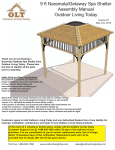
9x6 Cabana
Assembly Manual
Version #12
March 15th, 2012
Thank you for purchasing
a 9x6 Cabana. Please take
the time to identify all the
parts prior to assembly.
Note: The General Assembly
Manual illustrates a Door
Configuration in the front
center location. The Door
can also be positioned in the
front corners. To correctly
configure Door in front
corners,
follow
general
assembly steps and refer
to Page 25 for required
changes.
Safety Points and Other Considerations
Our products are built for use based on
proper installation and normal residential
use, on level ground. Please follow the
instruction manual when building your
shed and retain the manual for future
maintenance purposes.
Some of the safety and usage measures you may wish to consider include:
-snow load ratings vary by geographical location. If heavy or wet snowfall occurs, it is advisable to sweep the
snow off the roof(s).
-if the product is elevated, any structural and building code requirements are solely the customer's
responsibility, and should be abided by.
-in high or gusty wind conditions it is advisable to keep the structure securely grounded.
-have a regular maintenance plan to ensure screws, doors, windows and parts are tight.
Customer agrees to hold Outdoor Living Today Partnership and any Authorized Dealers free
of any liability for improper installation, maintenance and repair.
In the event of a missing or broken piece, simply call the Outdoor Living Today
Customer Support Line @ 1-888-658-1658 within 30 days of the delivery of your
purchase. It is our commitment to you to courier replacement parts, free of charge,
within 10 business days of this notification. Replacement parts will not be
provided free of charge after the 30 day grace period.
1-888-658-1658
www.outdoorlivingtoday.com
Page 1
[email protected]
Thank you for purchasing our 9x6 Cabana.
Please take the time to identify all the parts prior to assembly.
Parts List:
D. Miscellaneous Section
A. Floor Section
Bottom Skirting
10 - 1/2” x 4 1/2” x 34 3/4” Bottom Skirting
3
2
1
4
3
3
-
35” x 75” - Floor Joist Frames
48” x 75” - Plywood Floor - Large
9” x 75” - Plywood Floor - Small
1 1/2” x 3 1/2” x 72” - Floor Joists
1 1/2” x 3 1/2” x 57” - Floor Runners - Long
1 1/2” x 3 1/2” x 48” - Floor Runners - Short
Corner & Wall Trim
4 - 1/2” x 4 1/2” x 82” - Wide Corner Trims
8 - 1/2” x 2 1/2” x 79” - Narrow Trims
2 - 1/2” x 2 1/2” x 77 1/2” Side Wall Narrow Trims
4 - 1/2” x 2 1/2” x 75” - Filler Trims
4 - 1/2” x 4 1/2” x 33 1/2” - Horizontal Gable Trims
B. Wall Section
Main Wall Panels
7 - 35”w x 75”h Solid Wall Panels (7 walls with Bottom Plates Unattached)
7 - 1 1/2” x 2 1/2 x 35” Bottom Wall Plates
2 - 35” x 75” Window Wall Panels
Door Jambs & Header
2 - 1 1/2” x 3” x 73” - Vertical Door Jambs
1 - 2” x 3” x 35”- Door Header (Dado cut on edge)
Facia Trim
4 - 3/4” x 3 1/2”
4 - 3/4” x 3 1/2”
2 - 1/2” x 3 1/2”
2 - 1/2” x 4 1/2”
2 - 1/2” x 5 1/2”
x 46” - Side Facia - Angle cut both ends
x 57 1/4” - Front & Rear Facia- square cut
x 8” - Facia Detail Plate Pieces (front and rear)
x 8” - Horizontal Gable Trim Detail Plates
x 8” - Pentagon Facia Plates- (sides)
Filler Shingles
12 pcs - Long
4 pcs - Short
Gable Walls
2 - Side Gable Walls - Triangular shaped
Top Wall Plates
4 - 3/4” x 2 1/2” x 50” - Front & Rear Top Wall Plate - Angle cut on edge
2 - 3/4” x 2 1/2” x 75” - Side Top Wall Plate - Angle cut on ends
C. Rafter and Roof Section
18 - 1 1/2” x 3 1/2” x 45” - Rafters (angle cut)
2 - 3/4” x 4 1/2” x 44” - Ridge Boards
2 - 3/4” x 4 1/2” x 61” - Ridge Boards
4 - 1/2” x 4 1/2” x 52 1/2” Soffits (Front and Rear)
Door
1 - 31 1/2” x 42” - Bottom Dutch Door Section
1 - 31 1/2” x 30” - Top Dutch Door Section
1 - 1/2” x 1 1/4” x 32” - Horizontal Door Trim
2 - 1/2” x 2 1/2” x 72” Interior Vertical Door Stops
1 - 1/2” x 2 1/2” x 36” - Interior Top Horizontal Door Stop
Ridge Caps
1 Bundle Cedar Shingle Roof Ridge Caps - 18 pcs
**Miscellaneous Pieces
Roof Panels
4 - Outside Roof Panels 41” (Shingles overhanging roof battens on 1 end)
2 - Middle Roof Panel 35” (Shingles flush with roof battens)
3 - 3/4” x 3 1/2” x 48” Roof Gussets (angle cut on ends)
1
2
2
2
2
pc - Spare Wall Siding
- Window Inserts
-Window Trim Pkg - (1-24 1/16” angle cut / 3 -23” square cut)
pcs - Shim Shingles- use to shim door, etc
- Flower Box Kits (Assembly Manual & Hardware found in each Kit)
Note: All Trim, Facia and Bottom Skirting pieces will be positioned rough face out when installed.
Toll Free 1-888-658-1658
www.outdoorlivingtoday.com
Page 2
[email protected]
9X6 CABANA HARDWARE PACKAGE
Hardware Kit
(Provided)
Note: screws and nails shown actual size.
3”
3/4”
2 1/2”
3/4”
Silver
Black
1 1/4”
2”
Finishing
1 1/4”
2”
Black
1 1/4”
Square Drive Bit
Tee Hinge x4
Door Handle
Barrel Bolt
Simpson Strong
Tie (Roof) x 8
Ridge Board Connector x 2
Silver Barrel Bolt
Tools Required
Hammer
Shingle
(Not Provided)
Tape Measure
Screw Gun/Drill
Level
Pliers
Ladder
Safety Equipment Required
Safety Glasses
Toll Free 1-888-658-1658
Wood Clamp
1/8” & 3/8” Drill Bits
(Not Provided)
Work Gloves
www.outdoorlivingtoday.com
Page 3
[email protected]
A. Floor Section
Exploded view of all parts necessary to complete
Floor Section. Identify all parts prior to starting.
Plywood Floor
Small
Plywood Floor
Large (2)
Floor
Joist (4)
Floor Joist
Frames (3)
Concrete Pad
(optional foundation
method)
Floor Runners
Long (3)
Floor Runners
Short (3)
Inside Frame
to Inside Joist
You can find the
Square Drive Bit for
the screws in with
the Hardware Kit Bag.
10 3/4”
13 3/4”
1.
Attach Interior Floor Joists to Floor Joist Frames.
Only the Center Floor Joist Frame requires 2 Joists to be
9”
attached.
Measure and attach both Joists with Middle of joist to
2 - 2 1/2” screws per joist end as illustrated to the right. middle of joist
Toll Free 1-888-658-1658
www.outdoorlivingtoday.com
Page 4
Outside Frame
to outside Joist
[email protected]
17 1/2”
2.
Both Outside Floor Joist Frames require 1 interior Floor Joist attachment. Center Joist
(17 1/2”) from Outside of Floor Joist Frame to center of Floor Joist and attach with 2 - 2 1/2” screws
per end.
Center Frame
3. Position completed Floor Joist Frames with
75”
center frame in the middle. Attach the floor joist
frames together with 6 - 2 1/2” screws per
section. When completed, your floor joist
section should be 105” wide x 75” deep.
105”
Short Runner
Long Runner
Centered
Short Runner
Flush with Floor Framing
4.
Attach Floor Runners to completed floor frame. There are 2 floor runners per 105” side and
3 completed Runners in total. Each completed Runner will have a long and short piece. Use
10 - 2 1/2” screws to secure long Runners and 8 - 2 1/2” screws to secure short Runners. Reverse
long and short position of centre Runner to provide more floor strength.
Toll Free 1-888-658-1658
www.outdoorlivingtoday.com
Page 5
[email protected]
Concrete Slab
Foundation
5. With Floor Runners attached, carefully flip the floor over
and place on your foundation. Caution: you will need 2
people to assist you. Be careful when laying floor down not
to bend or twist floor. When in place, level floor completely.
Foundations
Note: The floor will be flipped over and floor
runners will sit on your foundation. It is
important to note that having a level foundation
is critical. Choosing a foundation will vary
between regions. Typical foundations can be
concrete pads or patio stones positioned
underneath the floor runners.
6. Position Plywood Floor pieces (3) on top
of completed Floor Joists. Plywood will sit
slightly back from outside edge of Floor Joist
Framing. When in correct position, attach with
1 1/4” screws. Use screws every 16”. The
Plywood is cut slightly smaller than floor framing. Keep plywood seams tight.
plywood
pushed together
at seam.
Hint: Use a chalk
line to mark location
of floor joists to
determine
screw
placement.
Front
7.
When completed, make sure
the floor is still level and make
adjustments if required. When
completed, your floor should look
similar to this.
1-888-658-1658
Completed Floor
www.outdoorlivingtoday.com
Page 6
Important - Make
sure floor is level
before moving on to
wall section. Use a
level to confirm and
shim floor joists as
required.
[email protected]
B. Wall Section
Exploded view of all parts necessary to
complete the Wall Section. Identify all parts
prior to starting.
Front and Rear Top Wall Plate (4)
(Angle cut down length)
Side Gable
Wall Panel (2)
Side Top Wall
Plate (2)
(Angle cut on end)
Door Header
Window
Insert (2)
Solid Wall
Panel (7)
Window Wall
Panel (2)
Bottom Wall
Plates (7)
Vertical Door
Jamb (2)
8.
Lay out all the
wall
panels
and
become familiar with
their location.
On
Standard Kits, there
are 2 Window Wall
Panels and 7 Solid
Wall Panels. Make
sure
to
position
panels correct side up
so water is directed
away from and not
into shed. Compare
solid panels with
window wall panels to
determine if in upright
position.
Toll Free 1-888-658-1658
www.outdoorlivingtoday.com
Page 7
[email protected]
Wall Plate
9.
Starting with Solid Wall Panels, carefully lay panel face down. Position and attach Wall Plate
to bottom of wall studs of each wall panel with 3 - 2 1/2” screws. Position so plates are flush with
framing.
10.
Starting at Rear Corner, position a
Solid Wall Panel on top of plywood floor.
Depending on your preference, you may
use a solid or window wall panel in this
position. If using a solid wall, make sure
panel is facing up.
1st Rear
Wall Panel
Side
Important - Make sure all walls are aligned
in their upright position. If not, water may
leak into your shed. Unsure if panel is
facing up or down? Check siding on
window wall panel and match alignment.
Fro
nt
1st Rear Wall Panel
11. The front and rear wall panels will sit flush at
the end of the plywood floor with the side panels
sandwiched between them. Note: Siding will
overhang the floor by approx. 1/2” but 2x3 wall
frame will sit flush on plywood floor.
all
x3 w
e
fram
2
side o
f shed
Flush with Floor Framing
1-888-658-1658
www.outdoorlivingtoday.com
Page 8
[email protected]
side
wall
ll
rear wa
2 1/2” screws
Optional - Caulking
seams will help prevent
moisture from entering
your shed. Caulking not
included in kit.
Side Wall
Panel
12. Position 1st side wall panel on plywood
floor so once again 2x3 wall plate is sitting
flush on floor. Position panel so 2x3 framing
sits flush with rear wall framing.When both
wall panels are positioned correctly, attach
together at top, middle and bottom of vertical
studs with 2 1/2” screws.
Important - Do not
fasten walls to
floor until Step 21.
Re
W
al
l
Si
de
W
al
l
ar
13. When correctly aligned, looking from the
top view, 2x3 wall framing of corner wall
panels will be positioned as illustrated above.
14. Position and attach 2nd rear wall panel as
shown above. Attach adjacent wall studs
together with 3 - 2 1/2” screws.
15. Position and attach 3rd rear wall panel and attach as per Step 14.
Note: wall framing of 3rd
rear wall should sit flush with floor framing.
Toll Free 1-888-658-1658
www.outdoorlivingtoday.com
Page 9
[email protected]
16. Complete attachments of remaining
side walls as per Steps 11-15.
17.
Locate Window Inserts and Window Trim Packages. Before installing, run a bead of
caulking around window opening perimeter. Position window in cavity and secure with 8 - 1 1/4”
screws. Position Window Trim around window doing a dry run first and attach with 4 - 1 1/4” finishing
nails per piece. Trim Sizes = 1x 24 1/16” = top / 3 x 23” = Sides & Bottom.
18.
Position and attach both Window Walls as per Steps 11-15.
1-888-658-1658
www.outdoorlivingtoday.com
Page 10
[email protected]
dado edge
to front
19. Attach both Vertical Door Jambs
Flush
on
Outside
to door opening wall studs with 4 - 2 1/2”
screws per Jamb. Position so jamb is
flush with outside wall paneling.
20. Attach Door Header to vertical door jambs
with 2 - 2 1/2” screws per side. Make sure jamb
is flush with outside wall paneling once again.
Screw from door header into door jambs.
21.
When all walls are attached
together, check alignment with the floor.
Bottom of wall frame should sit flush
with outside of floor framing, with siding
overhanging by approximately 1/2”.
Confirm 32” wide door opening at
bottom. When positioned correctly,
fasten bottom wall plates to floor using
4 - 2 1/2” screws per wall panel.
bottom plate
of wall.
Angle
screws into perimeter
Floor Joists.
Optional - Caulking
seams will help prevent
moisture from entering
at seam. Caulking not
included in kit.
Doorway Opening is 32”
Ca
ulk
ing
22.
Position one
angle cut Side Top
Plate on top wall
framing so they are
flush.
Attach by
screwing down into
top of wall frame
with 4 - 2” screws.
Toll Free 1-888-658-1658
www.outdoorlivingtoday.com
Page 11
[email protected]
Complete all
other Top Plate
attachments.
Front Top Plate
23. Next, attach the Front Top Plates (2 per side).
The front and rear top plates are angle cut down
the length. Once again, position top plate on wall frame so it is flush. Front and rear top plates will fit
between side top plates. Attach with 4 - 2” screws per plate.
24. Place Side Gable Wall so 1x3 framing sits flush with the
Flashing to overhang
wall on outside.
inside of the top plate. It should also be centered sideways on
the top plate. Adjust gable accordingly. Temporarily attach to
walls and top plate with 2 - 2” screws. Gables may need slight
adjustment in Step 35. Complete attachment in Step 35 with an
additional 6 - 2” screws. Screw from the bottom of gable framing
down into Top Plate and Wall. Hint: Use a straight edge to
check the angle of the gable framing and top plate. Both angles
should line up.
Use straight
edge to check
that angle of
gable lines up
with top plate
angle. Adjust
gable for best
fit.
25.
Align and attach opposite Side
Gable Wall as per Step 24.
Flashing will overhang wall
on outside. (See Step 53).
1-888-658-1658
www.outdoorlivingtoday.com
Page 12
[email protected]
C. Rafter and Roof Section
Exploded view of all parts necessary to complete the Roof Section.
Identify all parts prior to starting. (Roof Filler Shingles Missing)
Outside
Roof
Panels (2)
Middle Roof
Panels (2)
Outside
Roof
Panels (2)
Metal Ridge
Board
Connectors (2)
Ridge Boards (4)
44” and 61” long
Roof
Rafters
(9 per side)
18 total
Soffits (4)
1/2” x 4 1/2” x 52 1/2”
Roof Gussets
(3)
Metal Ridge Board Connector
8 - 3/4” screws
Ridge Board
Ridge Board
26.
Locate (1 each) 3/4” x 4 1/2” x 44” & 61” Ridge Boards and attach together with Metal Ridge
Board Connector using 8 - 3/4” screws. Total Length when connected is 105”. Complete two Sets.
Position Metal Ridge Board Connector evenly on Ridge Boards.
Toll Free 1-888-658-1658
www.outdoorlivingtoday.com
Page 13
[email protected]
2 1/2” Screws
into Doubled
up Rafters
Ridge Board
27.
Locate 9 Rafters, 2 Soffits and
completed Ridge Board. Lay out on level
ground as shown to the right. Double up
Rafters as illustrated. Screw doubled up
Rafters together with 3 - 2 1/2” screws
per piece.
2 1/2” Screws
into Doubled
up Rafters
Soffits
Double up
Rafters
28.
Attach completed Ridge Board to ends of both
outside rafters with 2 - 2” screws per end. Measure and
position interior Rafters as illustrated below. When
positioned correctly, attach Ridge Board to remaining
rafters with 2 - 2” screws /rafter end.
Important: Pilot
Hole Ridge Board
to prevent splitting!
105”
15 1/4”
15 1/4”
Connector
Plate to
inside
35”
15 1/4”
35”
35”
52 1/2”
So
ffit
Important: Pilot
Hole Soffit to
prevent splitting!
Rafter
1-888-658-1658
29.
Attach end of a 52 1/2” long Soffit Board flush to ends of
outside rafters with 2 - 1 1/4” screws per rafter end. Drill pilot hole
in Soffit ends to prevent splitting. Complete both outside
rafter / Soffit connections first. Measure and position interior
Rafters as illustrated above. When positioned correctly, attach
Soffits to remaining rafters with 2 -1 1/4” screws /rafter. Flip
completed rafter section over. Complete 2nd Rafter section now
as per Steps 27 - 28 with the following exception - When
attaching Ridge Board to Rafter ends, make sure Metal Ridge
Board Connector is positioned so offset to first Rafter
Section. See Step 33 for illustration.
www.outdoorlivingtoday.com
Page 14
[email protected]
30.
Flip Rafter Section over so
Soffit is down. Starting with the rear
Section, lift completed rafters up and
place on gable framing.
31.
Slide Rafter Section up on gable
framing until bottom of Ridge Board
slips into gable notch.
Ri
dg
e
Bo
Ra
fte
r
ar
d
Gable Notch
Soffit should sit
approx. 1/8” away
from wall panel.
32.
When Rafter Section is correctly positioned, outside rafters will sit equally on gable framing and
Soffit will sit approximately 1/8” away from wall panels.
Toll Free 1-888-658-1658
www.outdoorlivingtoday.com
Page 15
[email protected]
33.
Place front completed Rafter Section
on gable walls as per Steps 31 & 32.
rd
e
dg
Ri
a
Bo
Offsetting Metal Ridge
Board Connectors
Gable Notch
34.
At the peak, align Ridge Boards so
they are flush together and secure them with
12 - 1 1/4” screws. Important: if there is a
gap between Ridge Boards, have a helper
push
the
front
and
rear
walls
closer together from outside. Walls should
be 70” apart at top from inside of wall plate to
wall plate. To completely secure Ridge
Boards, place 4 - 1 1/4” screws into any of
the remaining Metal Ridge Board Connector
holes. Complete both sides.
35.
With both Ridge Boards
connected, completely secure
Gable framing to walls and rafters.
Use 4 - 2” screws per Rafter. Use
an additional 6 - 2” screws to
secure Gable to wall. Note: you
may have to remove the 2
temporary screws in Gable from
Step 24 and reposition Gable for
best fit prior to completing gable
attachment.
1-888-658-1658
www.outdoorlivingtoday.com
Page 16
[email protected]
ss
cro
”a
70
36.
Secure Rafters to Top Wall Framing with one 3” screw per rafter. Screw through Wall Frame at
an angle. Have two helpers push the Front and Rear Walls at the top from the outside of shed until
inside to inside measurement between the Top Plates is 70”.
37.
Roof Gussets are positioned on mid rafters.
Slide gusset up on side of rafters. Gusset must be
below top edge of rafter. Use level to square gusset
and attach to rafters with 4 - 2” screws. Pilot hole each
Gusset end with 1/8” drill bit.
Exploded view of upside
down roof panels.
38. Complete remaining 2 Gussets as per
Step 37.
Shingles overhang plywood
on outside panels.
Outside Roof
Panel.
Shingles and plywood
flush on middle panel.
39.
Identify all Roof Panels. There are 4 Outside and 2 Middle Roof Panels. Outside Panels will
have shingles overhanging the plywood on one end. Lift up and place an Outside Roof Panel on
Rafters.
Toll Free 1-888-658-1658
www.outdoorlivingtoday.com
Page 17
[email protected]
1 - 2 1/2” Screw in
Bottom Row of
Shingles
Angle Screw from Rafter
into Plywood with 2 1/2”
screw as seen in Step 42.
Roof Plywood
flush with rafter
end.
40.
Place Outside Roof Panel so it sits flush on 3rd rafter from the outside (doubled up rafter).
Plywood on roof should be flush with end of rafter at bottom, and with seam of doubled up rafters.
From the outside, screw down through bottom row of shingles into rafter with 1 - 2 1/2” screw. Angle
a 2 1/2” screw from outside rafter into roof plywood.
41.
Locate Middle Roof Panel.(roof plywood flush with outside of shingles) and place on middle
rafters. Align panel as per Step 40 and screw panel down to rafters with 2 - 2 1/2” screws in the
bottom row of shingles.
Shingles overhang plywood
on Outside Roof Panel.
42.
Lift up, position and attach 2nd Outside Roof Panel on Rafters as per Step 40.
1-888-658-1658
www.outdoorlivingtoday.com
Page 18
[email protected]
Middle Panel
Outside Panel
Outside Panel
43.
Position and attach Front Roof Panels as per Steps 39-42.
Attach above the
exposure line.
Exposure Line
44.
Roof Filler Shingles are included to cover
roof seams. Starting at the bottom, slide the first
Long Shingle in until flush with other bottom
shingles. DO NOT ATTACH UNTIL STEP 46.
45. Screw first filler shingle down to rafters
using 1 - 2 1/2” screw per panel (2 in total).
Make sure to screw into both rafters.
4- 90 degree Simpson
Ties / Gable.
46. Slide in another filler shingle and attach as per Step 45.
On your last row of shingles, attach
smaller filler shingle with 2 - 1 1/4” Shingle nails near top to be covered by Ridge Cap in Step 56.
Position 2 Simpson Strong ties on plywood and outside rafters and secure with 4 - 1 1/4” screws.
8 ties in total.
Toll Free 1-888-658-1658
www.outdoorlivingtoday.com
Page 19
[email protected]
Mi
dR
aft
er
Plywood
3 - 2 1/2” screws angled
into each Mid Rafter
47.
To further secure roof panels, from the inside, drill pilot holes in each Mid Rafter (3 per Rafter)
on an angle. Using 3 - 2 1/2” screws, secure rafters to roof plywood. Note: from outside, have a
helper push roof panel down so plywood sits flush against rafter when securing.
D. Miscellaneous Section
Exploded view of all parts necessary to complete the Miscellaneous Section. Identify all parts prior to starting.
Note: missing from exploded drawing: Interior Door Stops; 1 Interior Barrel Bolt
Rear Wall Narrow Trim (2)
Pentagon Facia
Plate (2)
Ridge Caps
Facia & Hor.
Gable Detail
Plate (4)
Side
Facia (4)
Front and
Rear Facia (4)
Horizontal
Gable
Trim (4)
Horizontal
Door Trim
Dutch Door
Top
Flower Box
Kits
Dutch Door
Bottom
Side
Narrow
Trim (2)
Bottom Skirting
Front & Rear (6)
Door Pull Handle
& Exterior Barrel
Bolt
Door
Hinge (4)
1-888-658-1658
Bottom Skirting
(Side) (4)
Doorway
Narrow
Trim (2)
Corner
Narrow
Trim (4)
Filler Trim (4)
www.outdoorlivingtoday.com
Page 20
Wide Corner
Trim (4)
[email protected]
Expert Advice: When installing trim, sort pieces according to color and pieces that are most
pleasing to the eye. Start with least visible side of shed and use the least desirable pieces first. Install
trim to most visible side of shed as your skill installing trim improves.
ng
e
sid
ti
kir
s
3 pieces of Bottom Skirting
for front and rear.
48. Attach Bottom Skirting around the base of the shed. Skirting will hide floor framing.
Gaps on
outside will be covered by Wide Trim pieces later. Start with front and rear skirting pieces first and
attach with 4 - 1 1/4” finishing nails per piece.
Side S
kirting
49.
Attach Filler Trims (4 - 1/2” x 2 1/2” x 75”) to each corner side wall. Align Filler Trims so they
sit flush with top of Bottom Skirting. Hammer with 8 - 1 1/4” finishing nails per trim.
50. Align and attach both Narrow and
Wide Trims to each corner. Starting
with a Narrow Trim (1/2” x 2 1/2” x 79”),
align tight underneath Soffit and Rafter.
Narrow Trim will cap Wide Trim when
attached in Step 51.
Use
8 - 1 1/4” finishing nails to secure. Note
that Narrow Trim will sit slightly below
Bottom Skirting when correctly
attached. Do a dry run with both Narrow
and
Wide
Trims
prior
to
attaching to confirm positioning.
Narrow Trim
sid
e
of
sh
ed
Toll Free 1-888-658-1658
www.outdoorlivingtoday.com
Page 21
[email protected]
51.
Narrow Trim
Caps Wide
Trim
4 1/2”
Position Wide Trim
(1/2” x 4 1/2” x 82”) over
Filler Trim and tight against
overhanging Narrow Trim.
Align Wide Trim at bottom
with Narrow Trim so flush
with each other. Secure trim
with 8 - 1 1/4” finishing nails.
Complete remaining corner
trims.
52.
Rear Wall Narrow Trim
Attach Rear Wall Narrow Trim
(2 - 1/2” x 2 1/2” x 79”) where wall
panels come together and leave a
seam. Position trim equally on wall
seam and tight underneath Soffit
and Rafter. Use 8 - 1 1/4” finishing
nails per piece to secure. Attach
both Side Wall Narrow Trims
(77 1/2” long) where wall seams
come together on sides. Position trim
equally
on
wall
seam
and
slightly below Bottom Skirting as per
Narrow Trim. Use 8 - 1 1/4” finishing
nails per piece to secure.
Side Wall Narrow Trim
54. Attach Side Facia (angle cut on ends) to end
53.
Attach Horizontal Gable Trims
(4 - 1/2” x 4 1/2” x 33 1/2”) to both sides of
shed (2 per side). Position over gable and
wall seam. Use 4 - 1 1/4” finishing nails to
secure each piece. Align Gable Trim with top
of Wide Trim as illustrated above.
1-888-658-1658
roof panel plywood. Line facia up to form a peak
and attach to plywood with 6 - 1 1/4” finishing nails
per piece. End of facia should be aligned flush with
end of rafter. See Step 55 for detail. Gap where
facia boards come together at peak will be covered
in Step 58.
www.outdoorlivingtoday.com
Page 22
[email protected]
Si
de
cia
Fa
Front
Facia
55.
Attach Front and Rear Facia to roof rafter
ends. There are 2 facia pieces per side. Secure
with 8 - 1 1/4” finishing nails per piece.
Front Facia will
overlap Side Facia.
Alternate Ridge Cap Seams
(Offsetting angle cut at peak)
9” from end
Important: Butt (thick) end
of Ridge Cap will be facing
towards the outside of shed.
56.
Place First Roof Ridge Cap on roof peak overhanging shingles by approximately 1”. Attach with
2 - 1 1/4” Shingle Nails 9” from end. Place 2nd Ridge Cap 1” back from 1st cap. Attach with
2 - 1 1/4” Shingle Nails 9” from end. There are left/right Ridge Caps, alternate each Ridge Cap as you
proceed.
8”
8”
57.
Place 3rd Ridge Cap 8” back from 2nd (enough to cover
shingle nails). Attach 3rd Ridge Cap down as per Step 56. Continue
to position and attach Ridge Caps until half the roof is complete. From
opposite side, position and attach Ridge Caps as described above.
Score/cut 1 Ridge Cap to 12” or to fit in the center of roof. Attach
center cap with 2-4 - 1 1/4” Shingle Nails.
Toll Free 1-888-658-1658
www.outdoorlivingtoday.com
Page 23
[email protected]
Hor. Gable Detail Plate
Pentagon Facia Plate
Facia Detail Plate
58.
Attach Pentagon Facia Plate where Side Facia meet at the peak. Use 4 - 1 1/4”
finishing nails per piece to secure. Attach Facia Detail Plates to cover seams where Front and Rear
Facia Trim pieces come together. Secure each with 4 - 1 1/4” finishing nails. Attach Horizontal
Gable Detail Plates to both side gables with 4 - 1 1/4” nails per side. Horizontal Plates are larger than
Facia Plates.
Narrow Trims
Flush with inside
of door jamb.
59. Position the 2
2“ Screws
3/4” screw
Doorway Seam Trim
remaining Doorway Narrow Trims (2 - 1/2” x 2 1/2” x 79) pieces flush with inside
of door jamb and tight at top to soffit. Attach with 8 - 1 1/4” finishing nails.
Important: Hinge not
exactly as shown.
Top Door
Center Hinges
Top and Bottom Hinges
center on door trim.
Bottom Door
2” Black Screws
3/8” gap at bottom,
evenly spaced on sides.
Bottom Skirting
Bottom Door
60. Attach Door Hinges to Top and Bottom Dutch Door 61. Place Bottom Dutch Door panel into
sections. At this stage, door can swing open on the left or
right. Decide on your preference and attach hinges to
door (2 hinges per door). Center Hinges should be
positioned to edge of door trim to prevent hinges from
contacting each other while top and bottom hinges may
be centered on door trim. Use 2” & 3/4” black screws on
hinge / door attachment as shown above.
1-888-658-1658
position, 3/8” gap on bottom and evenly
spaced on sides, and attach hinge to
doorway seam trim with 2” black screws.
Use shim to help keep the door evenly
spaced on bottom. One of the extra roof
shingles (see parts list) can be used as a
shim.
www.outdoorlivingtoday.com
Page 24
[email protected]
m
r tri
oo
pd
to
1/4” gap
62. Place the Top Dutch Door Panel into place
and gap top and bottom panel 1/4” apart. Use a
shim once again to help you. Attach hinges to
trim with hinge hardware provided.
63.
Attach Horizontal Door Trim with
4 - 1 1/4” finishing nails to cover Header.
Important: Drill pilot
holes with 1/8” drill bit
prior to securing with
screws to prevent
wood splitting. On 3/4”
screw, drill shallow
pilot hole only.
Temporarily position Interior
Vertical Door Stop to help
align Interior Barrel Bolt.
2” Screws
Silver Barrel
Bolt
3/4” Screw
64. Attach Door Handle and Exterior Black Barrel
Bolt to door. Handle is positioned on top door, Barrel
Bolt on bottom door. Attach Black Barrel Bolt as
illustrated above with 2” & 3/4” Black Screws. Note
how female part of Barrel Bolt is positioned higher than
male. Do a dry run first to position Barrel Bolt correctly.
Door
Stops
inside of door as illustrated above. Use
3/4” silver screws to secure. Refer to Step
66 to allow for adequate clearance.
67.
66.
Attach Interior Door Stops to door framing
(Jambs and Header). Start with Vertical pieces
first. Stops should overlap doorway by 1/2”. Use
4 - 1 1/4” screws to secure each Stop. Attach
Horizontal Stop next using 3 - 1 1/4” screws.
Toll Free 1-888-658-1658
65. Attach Interior Silver Barrel Bolt to
Assemble Flower Box Kit with
Assembly Instructions found in each
Flower Box Kit. Position completed
Flower Box below bottom of window trim
and secure with 2 - 2” screws per box.
Screw from inside of box into the center
wall stud. Attach second screw 2”
underneath first screw and once again
into the wall stud. Install Flower Box Kits
underneath each window.
www.outdoorlivingtoday.com
Page 25
[email protected]
Alternate Door Configuration
(Door on Left or Right of Center)
To configure the Cabana so the Door
is positioned on the left or right of
center wall panel, follow the general
directions in this manual for a regular
door configuration and note the
following changes.
A. Follow sequential Steps 9-17 in the Wall
Section for regular configuration to position
and secure wall panels. For Door on left
side, align and attach two Window Wall
Panels in center and right positions. For
Door on right side, configure Window Walls
on opposite side.
B. With walls positioned and attached together, locate Door Jamb and orientate on Side Wall Panel
stud. Align Door Jamb so Flush with bottom wall plate of wall framing. Wall siding will overhang 1/2”
on outside. Plate will overhang doorway side by 1”.
Door Stops
D. Attach 1 Vertical and Horizontal Door
C. When correctly aligned, attach Door
Stop. See Step 66 for detail. May have to
trim Horizontal Door Stop to fit.
Jamb to wall stud with 4 - 2 1/2” screws.
1-888-658-1658
www.outdoorlivingtoday.com
Page 26
[email protected]
Congratulations on assembling
your 9x6 Cabana!
Note: Our Sheds are shipped as unfinished products. If exposed to the elements, the western red
cedar lumber will weather to a silvery-gray color. If you prefer to keep the cedar lumber looking
closer to the original color, we suggest that you treat the wood with a good oil base wood stain. You
may also wish to paint your new shed rather than stain it. In both cases we recommend that you
consult with a paint and stain dealer in your area for their recommendations.
We hope your experience
assembling your 9x6 Cabana
Garden Shed has been both
positive and rewarding.
We value your feedback and
would like to hear back from you
on how well we are doing in the
following areas:
1. Customer Service
2. On Time Shipping
3. Motor Freight Delivery
4. Quality of Materials
5. Assembly Manual
6. Overall Satisfaction.
Please call, write or email us at:
Outdoor Living Today
Canadian Address
9393 287th Street
Maple Ridge, British Columbia
Canada V2W 1L1
United States Address
P.O. Box 96
Sumas, Washington
USA 98295
Toll Line: 1.888.658.1658
|
Fax: 1.604.462.5333
Page 27
The materials contained in this
Assembly Manual may be downloaded
or copied provided that ALL copies
retain the copyright and any other
proprietary notices contained on the
materials. No material may be
modified, edited or taken out of context
such that its use creates a false or
misleading statement or impression as
to the positions, statements or actions.
|
[email protected]