1
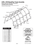
12'W x 9'H Barn Style Frame Assembly
Please read and understand instructions
completely before assembly.
Layout out frame parts as shown and match up items with quantity
to make sure no parts are missing.
End Rib
Middle Ribs
End Rib
Side
Rails
Cover Rails
301123 PACKING LIST BOX 1 OF 2
301123 PACKING LIST BOX 2 OF 2
Part #
Description
Qty.
Part #
Description
Qty.
800172
141° 4-way Side connectors
8
800172
141° 4-way Side connectors
8
800169
4-way Top connectors
4
800169
4-way Top connectors
4
800165
156° 3-way Side connectors
4
800165
156° 3-way Side connectors
4
800166
141° 3-way Side connectors
4
800166
141° 3-way Side connectors
4
12188
Rafter Poles
29 1/8"
10
12188
Rafter Poles
29 1/8"
10
12190
Middle Poles - Swedged
43 3/8"
8
12190
Middle Poles - Swedged
43 3/8"
8
12191
Cross Rails
45 1/2"
19
12191
Cross Rails
45 1/2"
19
800110
Middle Poles - Swedged
19 7/8"
4
800110
Middle Poles - Swedged
19 7/8"
4
10022
4-way cover rail clamp
16
10022
4-way cover rail clamp
16
10023
3-way cover rail clamp
8
10023
3-way cover rail clamp
8
10017
Bolts
1/4"*L2 1/2"
84
10017
Bolts
1/4"*L2 1/2"
84
1013
Bolts
1/4"*L2"
70
1013
Bolts
1/4"*L2"
70
1010
Nuts
1/4"
154
1010
Nuts
1/4"
154
1011
Gasket 1/4"
1/4"
20
Page 2
ATTENTION:
FOR MISSING OR
REPLACEMENT PARTS
OR QUESTIONS,
PLEASE CONTACT
CUSTOMER SERVICE:
1.800.524.9970
CANADA 1.800.559.6175
www.shelterlogic.com
150 Callender Road
Watertown, CT 06795
05-301123-0C 04/21/09
Basic Frame Assembly
800170
800165
STEP 1: ASSEMBLE END RIBS
Fig. 1
12188
12188
800165
12188
12188
800166
Fit together roof rib using the following parts:
(1) #800170 3-Way Top Connectors
(4) #12188 Rafter Poles
(2) #800165 3-Way Side Connectors
(2) #800166 3-Way Side ConnectorsUsing
(8) #10017 1/4" x 2 1/2" Bolts and
(8) Nuts securely fasten these tube.
Fig. 1
800166
Use #10017
1/4" x 2 1/2" Bolts
2 End Ribs
Fig.1
800169
STEP 2: ASSEMBLE MIDDLE RIBS
Fig. 2
800171
12188
12188
800171
12188
Fit together roof rib using the following parts:
(1) #800169 4-Way Top Connectors
(4) #12188 Rafter Poles
(2) #800171 4-Way Side Connectors
(2) #800172 4-Way Side Connectors Using
(8) #10017 1/4" x 2 1/2" Bolts and
(8) Nuts securely fasten these tube. Lay these ribs on the
ground at the rear of your shelters designated location.
Fig. 2
12188
800172
800172
Use #10017
1/4" x 2 1/2" Bolts
Middle Ribs
Fig.2
12191
STEP 3: ASSEMBLE ROOF FRAME
Fig. 3
Using #12191 Cross Poles,
#01013 1/4" x 2" Bolts and
#01010 1/4" Nuts to connect these ribs.
Fig. 3
Fig.3
STEP 4: INSTALL LEGS
Fig. 4
With help lift one side of the rafter assembly
and insert leg assemblies as shown in Fig. 4.
When all of the legs areinstalled on one side
of the rafter assembly, repeat the same
process on the other side.
800110
12190
800110
12189
Note: Bolts are required for these connections.
10005
Page 3
Fig. 4
STEP 5: INSTALL COVER RAIL
Fig. 5, Fig. 6
1013
clamps
10022
1011
Attach the #12191 cross rails using the 3-Way
and 4-Way cover rail clamps ar-ound the uprights
and losely fasten with 1/4" x 2" Bolts and Nuts.
Check the rails are evenly spaced above the
ground on both sides. Push down on the
connect-ors one at a time to tension the cover
and tighten the bolts to hold tightly.
Fig. 5 & Fig. 6.
1010
middle leg
1013
clamps
10023
1011
1010
Fig.6
corner leg
Fig.5
STEP 6: ATTACH & SECURE BASE FEET
Fig. 7
Depending on the model you have purchased, your base feet willeither fit
onto the outside of the leg poles, or slide inside the legpoles. After
installing Base Feet Plates onto bottom of Middleleg Poles,be sure to line
up the pre-drilled hole in the leg withthe pre-drilled hole in the base foot.
Insert 1/4" x 2 1/2" bolts all theway through leg and foot, to other side,
secure with nuts. Fig. 7.
Fig. 7
Note: The feet should sit reasonably flat on the ground.
STEP 7: INSTALL AUGER ANCHORS
Fig. 8
You will secure the anchors to the corner leg bendsusing the cable
and clamp. Be sure to put cable throughthe hole in the corner leg
bend, and through eye ofanchor, secure with clamp. Repeat
process attaching theremaining anchors to the middle ribs with the
cable around the upright above the foot plate.
Note: Anchors must be placed inside of shelter.
Fig. 8
Fig. 9
STEP 8: END PANEL INSTALLATION
Fig. 9, 10, 11
Starting from the peak, remove the cross pole from the
3-way top connector. Place exposed rope at the top of the
panel over the 3-way connector and under the cross pole as
shown in Fig. 9. Replace the cross pole. At each corner,
remove the cross poole and fold the fabric around to the
inside placing the 3-way socket through the opening in the
fabric as shown in FIg. 10. Tighten the panel by inserting the
“S” hooks into the holes inthe corner legs, pulling and tying
off as shown in Fig. 11. Repeat step 8 for another 2-zipper
door.
Page 4
Fig. 11
Fig. 10
STEP 9: INSTALLING THE
COVER ON THE FRAME:
Fig. 12A, 12B, 12C & 12D
1. Lay the cover on the ground next to the
frame with the inside of the cover (the side with
the pipe pockets) facing down and the webbing
on the front and rear of the corner of the
building. Position the cover so that it is
centered on the frame, front to back. Fig 12A
2. Fold over the side closest to the frame so
the pipe pocket is now accessible. Insert a
cover pipe at the first middle rib from the front
and the first middle rib from the rear so that it is
inserted in the pipe pocket on both ends of the
pipe but the center of the pipe is exposed. For
long buildings it may be necessary to use
additional pipes in the middle. Fig. 12B
Fig. 12A
3. Tie the rope on each of the exposed pipes
and throw the other end of the rope over the
frame. Fig. 12C
4. Move to the other side of the frame and pull
the cover over the frame with the rope. This
may require two or more people. Fig. 12D
Fig. 12B
Fig. 12C
Fig. 12D
Page 5
Outside Corner View
STEP 10: SECURE YOUR COVER:
Fig. 13A, 13B, 14 & 15
Pull the cover over the frame so the webbing is at the front and rear
of the frame and the internal pipe pocket runs along the bottom of the
frame. Use the (4) ratchets as shown in Fig. 13A. Adjust the cover
so there is equal overhand on the front and rear. WIth the webbing
and ratchets, pull the cover snug but not tight. Remove the sliding
cross rails from the lower part of the frame by removing the bolts from
the half clamps, If the pipe pocket is not cut already, cut it about 2-3”
from each side of the rafter pipe. Insert the sliding pipe into the pipe
pocket and install half clamps again. When all of the pipes are
re-installed, push down ont he sliding pipe to tighten the cover over
the frame. When the cover is pulled tight, secure the clamps in
place. When all of the half clamps are secured tight, finish the (4)
ratchets to make the final adjustment to the cover.
CORRECT
Fig. 13A
COVER TIGHTENING TIP
Check and tighten
Ratchets and Cross
Rails monthly to
ensure the cover
is tight.
INCORRECT
cross rails
12191
IS YOUR COVER
PULLED CORRECTLY
ON THE FRAME?
Fig. 13B
Fig.15
Fig.14
1013
clamps
1013
10023
Fig. 13B
clamps
10022
1010
1010
middle leg
corner leg
NOTE: ShelterLogic logo should line up on the left front and right rear corners near the top rail. If it is not legible and positioned
as shown above as “incorrect”, the cover has not been put on the frame correctly.
WARNING: Serious injury to persons or property could result if cover is installed and shelter is not completed and is left
unattended. Shelter must anchored down securely until completed.
Page 6
WARNINGS, CAUTIONS, CARE & CLEANING
WARNING
Prior to installation, consult with all local and municipal codes regarding the installation of temporary
shelters. Choose the location of your shelter carefully. Check for overhead utility lines, tree branches or
other structures.
• Do NOT install near roof lines or other structures that could shed snow, ice, or excessive run-off onto
your shelter.
• Do NOT install too close to other structures. A MINIMUM of 6 to 10 ft. is necessary between structures
to allow for snow removal.
• Do NOT hang objects from the roof structure or support cables.
• Do NOT smoke our use open flame devices in or around the shelter.
• Do NOT store flammable liquids (gasoline, kerosene, propane, barbeque grills, fire pits, deep fryers or
smokers inside the shelter).
• Do NOT use hard edged tools or instruments like rakes or shovels to remove snow. This could result in
punctures in the cover.
CAUTION
1. PLEASE READ AND FULLY UNDERSTAND THE INSTALLATION DETAILS AND WARNINGS PRIOR TO
FINAL INSTALLATION. IF YOU HAVE QUESTIONS IMMEDIATELY CALL THE CUSTOMER SERVICE
NUMBER LISTED ON PG. 2.
2. This product is classified as a temporary fabric covered shelter and is intended to protect what is stored
in it from basic environmental elements, including the effects of sun, rain, tree sap, bird and animal
excrement and light snow. IT IS NOT DESIGNED TO HOLD THE LOAD FROM HIGH WINDS, HEAVY
SNOW OR ICE STORMS.
3. Proper anchoring is the RESPONSIBILITY OF THE OWNER. Any shelter that is not anchored securely
and properly has the potential to blow away in high winds. ShelterLogic cannot be held responsible for
any shelter that blows away. NOTE: Your shelter’s cover can be quickly removed and stored prior to
severe weather conditions. If strong winds or severe weather is forecast in your area, we recommend
that you remove the cover.
CARE & CLEANING
A tight cover will ensure longer life and performance. Inspect and retighten the ratchet tie-downs monthly
as needed. Always maintain a tight cover. Loose fabric can accelerate deterioration of the cover.
Immediately remove any accumulated snow or ice from the roof structure with a broom, mop or other soft
sided instrument.
Do NOT use “protect and shine” or harsh or abrasive products to clean the fabric cover. Mild soap and
water is recommended to clean the fabric cover of your shelter.
Page 7