1
Monticello
TM
Made in the USA
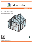
8’ x 8’ Greenhouse
Assembly Instructions
071812
10
YEAR
WARR ANT Y
Customer Service: (877) 373-3078 Email: [email protected]
65 Fleetwood Drive, Rockaway, NJ 07866
Introduction
Thank you for purchasing your MonticelloTM 8x8 Greenhouse. The Monticello line is proudly made in the USA
by a leading commercial greenhouse maker using the same professional grade materials and design. The frame
is constructed with the highest quality extruded aluminum with lead free powder-coated paint. The panels are
professional grade 8mm twin wall polycarbonate selected for their insulation and durability.
The Monticello line is a modular system, which uses an 8x8 greenhouse that can be easily expanded in four foot
sections up to 24 feet by 8 feet at any time. The 8x8 greenhouse include one roof vent with it’s own automatic
vent opener to ensure proper ventilation and maintain optimal temperature. When properly assembled
and maintained, this greenhouse will provide years of enjoyment. It can be expanded with four foot extension
kits as your needs expand.
Our greenhouse has been designed to be easily assembled. Although all but one step can be completed by one
person, we recommend using a helper for the entire assembly. You will need assistance from another person to
assemble the roof. Allow six to eight hours to complete. If you have never assembled a greenhouse before, make
it a weekend project. We recommend you take your time and read these instructions carefully to avoid mistakes.
NOTE: These instructions include helpful hints and important information needed to safely assemble and properly
maintain the greenhouse. Please read these instructions completely before you begin.
CAREFULLY READ ALL INSTRUCTIONS BEFORE YOU BEGIN.
FOLLOW STEPS IN THE ORDER PRESENTED. KEEP THIS MANUAL FOR FUTURE REFERENCE.
Before Starting Assembly:
1. Make sure you have all the necessary parts:
Compare the contents of the four cartons with the List of Parts. If any parts are missing or damaged or if you
have any questions, please contact Customer Service by phone at (877) 373-3078 or by email at
[email protected] before beginning assembly.
2. Lay the parts out in one staging area:
The List of Parts has the corresponding step number referenced to each part so you can easily prepare for
each step. We recommend placing all parts in one staging area. Lay out parts by size and shape. Use the List
of Parts to identify the part numbers for profiles and panels. We have not labeled the parts with stickers to
avoid removing them during assembly.
3. Select a Location:
When selecting a site for your greenhouse, a flat level surface is essential and if possible, with proper water
drainage and easy access to power and water necessary for greenhouse gardening. Choose a sunny, level
position away from overhanging trees and power lines and protected from the wind as much as possible.
The location should be away from structures that could cause snow to drift on or around the greenhouse.
Locate underground pipes or cables before preparing the site or anchoring the greenhouse.
4. Prepare a Foundation:
After choosing a location, proper preparation of the site is essential. The site must be level. The greenhouse
must be mounted to a base. Construct the base first so the greenhouse can be securely mounted.
We recommend constructing a wood platform base using a perimeter of two by fours filled with either soil,
sod or gravel. Instructions for constructing a wood platform can be found on page 3 in this manual.
Other suitable base options include wood decks and concrete slabs. Wood screws are included to secure the
greenhouse to a wood base. The greenhouse is secured to the ground from the inside with ground anchors.
See step11 for details. If you are using a concrete base, get appropriate mounting screws before beginning.
Make sure the corners are square by measuring the inside diagonals from both sides and making sure they
are equal. Use a spirit level to make sure the base is level.
Contact your local authorities regarding any required building permits or restrictions.
WWW.RSIWW.COM
1 of 44
Safety Advice
Table of Contents
The greenhouse must be positioned and fixed on a flat
level surface.
Dispose of all plastic bags safely. Keep them out of the
reach of small children.
Keep children and pets away from the assembly area until
the work is completed.
Always wear work shoes, gloves and safety goggles when working.
Some of the parts have sharp edges and burs. Use extreme
caution when handling.
Do not lean against or push the greenhouse during assembly.
Take special care not to touch overhead power lines with the
aluminum profiles.
Do not attempt to assemble the greenhouse in windy or wet
conditions.
Do not position your greenhouse in an area exposed to
excessive wind.
If using power tools or a step ladder, always follow the
manufacturer’s safety instructions.
Hot items such as recently used grills, blow torches etc.,
must not be stored in the greenhouse.
Store the polycarbonate panels in a cool dark place such as a
garage until you are ready to use them.
Make sure the greenhouse complies with local building codes.
Introduction ..........................................
Safety Advice ........................................
General Order of Assembly .............
Construct Wood Platform ................
List of Parts ............................................
Prepare Set Screws .............................
Assemble Base ......................................
Assemble Right Wall ...........................
Assemble Back Wall ............................
Assemble Left Wall ..............................
Assemble Front Wall and Gable ......
Assemble Back Gable .........................
Assemble Roof Ridge .........................
Assemble Roof .......................................
Install Roof Vents .................................
Install Doors ..........................................
Secure to Platform ...............................
8
1
2
2
3
4
7
7
10
14
17
21
27
30
32
39
41
44
7
6
General Order of Assembly
Step 1: Assemble Base
Step 2: Assemble Right Wall
Step 3: Assemble Back Wall
Step 4: Assemble Left Wall
Step 5: Assemble Front Wall and Gable
Step 6: Assemble Back Gable
Step 7: Assemble Roof Ridge
Step 8: Assemble Roof
Step 9: Install Roof Vents
Step 10: Install Doors
Step 11: Secure to Platform
9
4
3
5
2
11
1
10
Tools Needed
Work Gloves
Safety Goggles
Step Ladder
Tape Measure
Spirit Level
Wrench (included)
2 of 44
Phillips Screwdriver (included)
23 inch spacer (included)
5 foot bungee cord (included)
WWW.RSIWW.COM
Constructing a Wood Platform
!
IMPORTANT: It is very important to begin with a level surface. Check your foundation to ensure it is level at every
point. If you are not building on a wood deck, we recommend constructing a wood platform so you can properly
secure the greenhouse. You must assure your foundation is square and level before beginning assembly.
After choosing a location, proper preparation of the site is essential. The site must be level. Create a wood
platform using a perimeter of pressure treated two by fours filled with either soil, sod or gravel.
NOTE: When constructing the greenhouse on a wood deck, make certain the
surface is level. Creating an additional wood platform is not necessary.
Buy pressure treated 2x4 lumber. You will use two layers with the corner positions staggered for maximum
strength. The finished dimensions will be 101” by 101”
Tools:
Spirit Level
Corner Square
Phillips Screwdiver
Power Drill (recommended)
Materials:
Eight 10’ pressure treated 2x4 lumber cut to 97½”
Fifty #8 3” wood screws
Make sure each corner is square and then secure one corner with wood screws.
Move to the diagonal corner, make sure it is square and then secure with wood
screws. As you continue to secure the 2x4 wood platform, continue to make
certain the corners are square and the frame is level.
Secure wood platform every two feet with wood screws. Make certain to tighten screws into the wood platform
until they are flush with the surface.
NOTE: The illustrations throughout the manual are shown without a foundation.
WWW.RSIWW.COM
3 of 44
List of Parts
The greenhouse is shipped in four cartons. These cartons are heavy. Use care when lifting them.
Some parts have sharp edges. Use extreme caution when handling.
Wear proper safety gear including work shoes, gloves and safety goggles.
Keep children and pets away until assembly is complete.
Finish assembling the roof in one session. Do not leave the roof unattended until it is completely assembled.
Place all like parts together in a staging area. Prepare for each step according to instructions in this manual.
If any parts are missing or damaged, contact Riverstone Customer Service before beginning assembly:
Customer Service: (877) 373-3078 or email: [email protected]
Profile
Profile
QTY
56”
QTY
23”
F-1
17
Steps
2,3,4,
5,8
F-10
2
Step 3
G-1
4
Steps
2,4
G-2
2
Steps
2,4
P-1A
4
Step 1
P-1B
4
Step 1
R-1
2
Step 7
25 ½”
31”
F-2
1
Step 6
15 ⅞”
48 ½”
F-3
4
Steps
5,6
20 ½”
50½”
F-4
1
Step 5
47 ¼”
50½”
F-5
1
Step 5
49 ¾”
23”
F-6
4
F-7
8
Steps
5,6
56”
Steps
2,3,4,
5,6
4 of 44
WARNING: Profiles with cut edges and/or drilled holes
are sharp. Use extreme caution when handling.
WWW.RSIWW.COM
List of Parts (continued)
WARNING: Use extreme caution when handling
panels with cut edges. The corners are sharp.
Panels
Connectors
QTY
W-1
21
Steps
2,3,4,8
QTY
B-1
6
Steps
4,6
B-2
6
Step 5
B-3
31
Steps
2,3,4,5,10
B-4
9
Step 8
B-5
9
Steps
1,2,4,7
B-7
6
Steps
5,6,7
B-8
4
Step 1
24” x 57”
W-2
1
Step 8
24” x 32 ¼”
W-3
4
Steps
4,5
24” x 15 ½”
W-4
2
Step 5
24” x 31 ¼”
W-5
2
Step 4
24” x 21 ¾”
Assembled Doors and Vents QTY
24” x 65”
D-2L
D-2R
D-2L
1
Step 10
D-2R
1
Step 10
Brace
V-2
1
Step 9
24” x 24 ¾”
WWW.RSIWW.COM
5 of 44
QTY
B-9
1
Step 8
List of Parts (continued)
Connectors
Hardware
QTY
QTY
S-1
C-1
C-2
Trim Plates
4
2
Steps
5,6
Step 7
QTY
B-6
2
Step 5
49 ⅜”
G-4
4
Step 8
Step 9
4
S-2A
239
S-2B
239
S-2C
239
Steps
1,2,3,4,5,
6,7,810,11
S-3
4
Step 10
S-4
50
Steps
1,11
S-5A
1
Step 7
S-5B
1
Step 8
S-2C
1
Step 8
S-6
2
Step 9
QTY
Included Tools
T-1
1
Steps
8,9,10,11
T-2
1
Steps
1,2,3,4,5,
6,7,8,10
T-3
1
Steps
2,3,4
T-4
1
Step 8
Phillips Screwdriver
QTY
Door Parts
37 ½”
D-1L
1
Step 10
D-1R
1
Step 10
Wrench
23” Spacer
D-3
2
Step 10
5’ Bungee Cord
Vent Opener
D-4
12’
Step 10
QTY
V-3
Ground Anchors
D-5
Gutter Drain
2
1
Step 9
QTY
Step 10
A-1
4
Step 11
A-2
4
Step 11
QTY
G-3
4
Step 8
6 of 44
WWW.RSIWW.COM
Assemble Base
Make certain the pieces are in the correct positions before assembling.
Carefully follow the order of assembly to ensure an easy installation.
Wear proper safety gear including work shoes, gloves and goggles.
1.1A We use a set screw and nut assembly
system for ease of installation. With
the hex shaped indent facing up,
screw S-2B threaded part into S-2A
nut until it is flush with bottom
of nut. When the assembly is flush
it will slide easily in the bolt tracks.
S-2B
set screw
S-2A
slides easily
NOTE: The two pieces together is referred to in this manual as a “set screw”.
Shown sliding into F-1 bolt track.
IMPORTANT: One end of the S-2B threaded set screw has a hex shaped indent. The other end
forms a soft point. Make sure indented hex is always facing up when screwed into the S-2A nut.
This way if the set screw is installed too tightly to loosen by hand, you can use a hex key.
1.1B After sliding into bolt track, screw threaded part
farther into nut so end touches the edge of the
profile and holds in place. Do not over tighten.
It will be difficult to loosen again to adjust
position to fit holes in connectors.
hand tightened
set screw
Shown hand tightened in F-1 bolt track.
NOTE: Screwing S-2B threaded part farther into nut so it holds is referred to in this manual as “hand tighten”.
“Loosen set screw” refers to unscrewing the S-2B threaded part enough so set screw easily slides.
NOTE: We recommend assembling all set screws before beginning. Each step shows quantity
needed separately. Connectors are secured with S-2C bolt using set screws in later steps.
1.2
The base is made up of four P-1A, and four P-1B profiles. Arrange profiles in a square as shown.
P-1A
P-1B
BACK
P-1B
P-1A
WARNING: Use extreme caution when handling profiles P-1A
and P-1B. The bottoms may have sharp edges near the drilled
holes. The cut edges on the corners of these profiles are sharp.
IMPORTANT: Make sure the base fits properly on your
foundation. If not, stop and fix your foundation.
P-1B
P-1A
FRONT
P-1B
WWW.RSIWW.COM
Profile
P-1A
QTY
50½”
7 of 44
P-1A
4
P-1B
4
1.3
Separate profiles to install set screws into inside and outside bolt tracks. Some of the set
screws will be secured in this step. Most are secured in later steps. They are difficult to install
after the base is assembled. Pay careful attention to ensure you have the correct number of set
screws in the correct bolt track in each profile. The profiles have different amounts of screws on
the inside and outside bolt tracks. The chart and illustration below show the set screw placement.
The squares represent screws that are used in steps 1.4A and 1.4B, the circles represent
screws used in steps 2 through 10 and the crosses represent screws used in step 11.
NOTE: Instructions identify twelve set screws necessary for securing to ground in step 11.
IMPORTANT: When assembling base, make sure the profiles are straight and flush against each other. Secure
profiles together, and ensure corners are square. The diagonal measurements on inside corners should be equal.
Secure corners to desired foundation until assembly is completed. We recommend using a two by four platform.
BACK
Set Screw Placement Code
Set screws used in steps 1.4A and 1.4B
Set screws used in steps 2 through 10
Set screws used in step 11
FRONT
S-2A
S-2B
8 of 44
65
65
WWW.RSIWW.COM
1.4A Make certain side profiles are straight and flush. Adjust position of set screws in
inner bolt track at front of profile to fit holes in B-5 connector. Center
connector over seam for maximum hold. Secure using five bolts. Repeat
on outer bolt track to install three remaining B-5 connectors at
back and sides.
B-5
B-8
B-5
B-5
BACK
IMPORTANT: One B-5 connector is installed on inside front.
Remaining B-5 connectors are installed on outside back
and sides. B-8 corner connectors are installed on inside.
B-8
B-8
FRONT
B-5
B-5
B-8
NOTE: Connector size is not shown
proportionally in this drawing.
1.4B Make certain corners line up
and are flush. Adjust position of set screws in inner bolt track to fit holes in B-8 connector.
Secure with four bolts. Repeat until each corner is secure.
B-8
IMPORTANT: Double check the position and
amount of unused set screws in the base. You
should have 29 available for later assembly.
Connector
QTY
B-5
S-2C
Connector
4
20
QTY
B-8
S-2C
4
16
1.5A Measure base diagonally from inside corner. Equal measurements ensure the base is square.
Use a spirit level to make sure the base is level.
1.5B Locate predrilled holes in base profiles.
Use six S-4 screws, one at each corner
and one in the center of each side to secure
to wood platform. You will secure the
greenhouse completely to the platform
in step 11.1 when assembly is finished.
S-4
B-8
Connector
QTY
S-4
WWW.RSIWW.COM
9 of 44
6
Assemble Right Wall
Make certain the pieces are in the correct positions before assembling.
Carefully follow the order of assembly to ensure an easy installation.
Wear proper safety gear including work shoes, gloves and goggles.
Prepare needed set screws as shown in step 1.1A
NOTE: Have the hex shaped indent facing up. Screw in until it is flush with bottom of nut so
it slides easily into bolt tracks. After inserting into bolt track, screw in until it holds in place.
2.1A Prepare two F-7 corner profiles. Slide set screws into all three bolt
tracks on one end and into two side bolt tracks on other end
of corner profiles. Hand tighten each set screw
to hold in place.
F-7
F-7
NOTE: Set screw in center bolt channel is used when installing optional
shelving units. Install F-7 profile with set screw near base until needed.
2.1B Prepare three F-1 wall profiles. Slide set screws into both bolt tracks on one end of profile and
one bolt track on the other end. The single set screw will sit on the inside of the greenhouse
near the base when installed.
F-1
F-1
F-1
2.1C Hand tighten each set screw
to hold in place.
Profile
QTY
56”
56”
WWW.RSIWW.COM
10 of 44
F-7
2
F-1
3
S-2A
S-2B
17
17
2.2A Begin at front right corner. Remove plastic film from both sides of one W-1
panel. Fit panel into channel in base, placing side marked “ UV Resitant”
facing outside. The panels will help hold the profiles up during assembly.
2.2B Place F-7 corner profile on base, fitting panel into channel. Slide
set screws into base so they line up. Fit B-3 connector on each side.
2.2C Secure with four S-2C bolts.
F-7
B-3
B-3
NOTE: VIEWS ARE FROM OUTSIDE.
2.3A Continue working from inside. Remove plastic film from both sides of one W-1 panel. Fit panel
into channel in base and corner profile, placing side marked “ UV Resitant” facing outside.
IMPORTANT: The panels expand and contract depending on the temperature.
To ensure proper placement, use the 23 inch spacer included with the tools.
2.3B Place 23 inch spacer on base next to F-7 corner profile. Fit panel into channel in F-1 profile and
slide F-1 profile against spacer to ensure proper placement. Position F-1 profiles so single set
screw is next to base on inside.
NOTE: Panels will not fit completely to end of channels.
There will be some space to allow for temperature changes.
F-7
W-1
F-1
2.3C Fit B-3 connector and secure with two S-2C bolts.
W-1
spacer tool
F-1
NOTE: VIEW FROM INSIDE.
B-3
2.3D Continue building the side wall from the inside. Use the spacer with each panel and the four
remaining F-1 profiles. Repeat steps 2.3A through 2.3C.
2.4
Add the last W-1 panel to complete the side. From the outside, fit F-7 corner profile into
place and secure.
F-7
NOTE: VIEW FROM OUTSIDE.
Panel
B-3
QTY
W-1
B-3
24” x 57”
11 of 44
5
Connector
QTY
B-3
S-2C
7
14
WWW.RSIWW.COM
2.5A
Prepare two G-1 gutter profiles by sliding four set screws into bottom
bolt track. Hand tighten each end set screw to hold in place.
G-1
G-1
2.5B Prepare one G-2 gutter profile with five set screws. Slide
set screws into bottom bolt track. Hand tighten
G-2
end set screw to hold in place.
Profile
QTY
25½”
S-2A
S-2B
2.6A
13
13
48½”
G-1
2
G-2
1
Working from inside, place G-1 and G-2 gutter profiles, fitting top edge of W-1 panels into
channels of gutters. Place one short G-1 gutter profile at each end and the two longer
G-2 gutter profiles in the center. Seams
are centered to bolt tracks in F-1 profiles.
G-2
G-1
W-1
F-1
F-7
F-1
NOTE: At front and back, edge of G-1 gutter
profile lines up flush with edge of F-7 corner profile.
at each end. Hand tighten both set screws to hold in place.
G-1
F-7
NOTE: VIEW FROM INSIDE.
G-1
W-1
F-7
F-7
S-2A
S-2B
NOTE: VIEWS FROM INSIDE.
WWW.RSIWW.COM
W-1
W-1
2.6B Place one set screw on the inside bolt track of the gutter
W-1
G-1
W-1
12 of 44
2
2
2.7A
The gutters are secured together using B-5 connectors and attached to
side profiles using B-3 connectors on the outside of the greenhouse.
The B-3 connector uses the set screw in the center hole of B-5
connectors at seams. Loosen and slide set screws to line up
with connectors making sure the seams line up and the
gutters remain straight.
2.7B Begin at the three seams and arrange set screws so middle screw is
centered. Fit B-5 connector onto gutter and hold in place
using the two end bolts.
G-2
B-5
G-1
B-5
W-1
F-1
W-1
F-7
NOTE: VIEWS FROM OUTSIDE UNDER GUTTER.
2.7C Loosen set screws on side profiles and slide down. Fit wide part of B-3 connector onto set
screw, slide up into place fitting gutter set screw at other end. Tighten set screws and
secure with bolts.
NOTE: The bottom of B-3 connector extends past the edges of side and
corner profiles. B-3 connector sits over B-5 connector. Secure all with bolts.
B-5
B-3
B-3
NOTE: VIEWS FROM OUTSIDE UNDER GUTTER.
Connector
QTY
B-5
13 of 44
3
Connector
QTY
B-3
S-2C
7
26
WWW.RSIWW.COM
Assemble Back Wall
Make certain the pieces are in the correct positions before assembling.
Carefully follow the order of assembly to ensure an easy installation.
Wear proper safety gear including work shoes, gloves and goggles.
Prepare needed set screws as shown in step 1.1A
NOTE: Have the hex shaped indent facing up. Screw in until it is flush with bottom of nut so
it slides easily into bolt tracks. After inserting into bolt track, screw in until it holds in place.
3.1A
Prepare one F-7 corner profile. Slide set screws into both bolt
tracks on each end of corner profile. Hand tighten each
set screw to hold in place.
F-7
3.1B Prepare three F-1 wall profiles. Slide set screws into both bolt tracks on one end of profile and
one bolt track on the other end. The single set screw will
sit on the inside near the base when installed.
Hand tighten each set screw to
F-1
hold in place.
F-1
F-1
3.1C Prepare two F-6 profiles. Slide set screws 3.1D
Prepare two F-10 profiles. Slide set screws
into both bolt tracks on each end of two
into both bolt tracks on each end of two
F-6 mitered profiles. Hand tighten
F-10 profiles. Hand tighten each set screw to
each set screw to hold in place.
hold in place.
F-10
F-10
F-6
F-6
S-2A
S-2B
Profile
QTY Profile
23”
23”
WWW.RSIWW.COM
F-6
2
F-10
2
14 of 44
32
32
QTY
56”
56”
F-7
1
F-1
3
3.2A
Working from inside, remove plastic film from both sides of one W-1 panel.
Fit panel into channel in base and corner profile, placing side marked
“ UV Resitant” facing outside.
IMPORTANT: The panels expand and contract depending on the temperature.
To ensure proper placement, use the 23 inch spacer included with the tools.
3.2B Place 23 inch spacer on base next to F-7 corner profile. Fit panel into
channel in F-1 profile and slide F-1 profile against spacer to ensure proper
placement. Position F-1 profiles so single set screw is next to base on inside.
F-7
NOTE: Panels will not fit completely to end of channels.
There will be some space to allow for temperature changes.
W-1
F-1
W-1
spacer tool
3.2C Fit B-3 connector and secure
with two S-2C bolts.
F-1
B-3
NOTE: VIEWS ARE FROM INSIDE.
3.2D Continue building the end wall from the inside. Use the spacer with each panel and the two
remaining F-1 profiles. Repeat steps 3.2A through 3.2C.
Panel
QTY
W-1
Connector
B-3
S-2C
3
24” x 57”
3.3
QTY
3
6
Add the last W-1 panel to complete the back. From the outside, fit F-7 corner profile into
place and secure.
F-7
B-3
B-3
Panel
NOTE: VIEWS ARE FROM OUTSIDE.
QTY
W-1
24” x 57”
15 of 44
1
Connector
QTY
B-3
S-2C
2
4
WWW.RSIWW.COM
3.4
The two sets of F-6 and F-10 profiles fit on top of W-1 panels. Line up
bottom bolt channels with top edge of F-1 and F-7 vertical profiles.
Profiles will fit snugly.
3.4A Working from inside right corner, place
F-6 profile with mitered end next
to corner and angled edge
facing up onto corner W-1
panel. F-6 profile fits snugly
between F-7 corner profile
and F-1 wall profiles.
F-6
G-1
F-1
3.4B Continue along back wall. Place first F-10 profile
on next W-1 panel. Make sure profile fits snugly
between the two F-1 wall profiles.
3.4C Place second F-10 profile on
next W-1 and ensure
F-10
it fits snugly.
F-1
W-1
F-7
W-1
F-6
F-10
F-7
W-1
F-1
W-1
F-1
F-10
F-1
3.4D Place second F-6 profile with mitered end next
to corner and angled edge facing up onto
corner W-1 panel. F-6 profile fits snugly
between F-7 corner profile and
F-1 wall profiles.
F-7
F-10
F-6
F-1
W-1
W-1
F-1
NOTE: ALL VIEWS FROM INSIDE.
3.5A
From inside, loosen set screws on profiles and adjust position to fit holes in B-1 connectors.
Fit B-1 connector to profiles as shown.
F-6
F-1
B-1
F-6
F-10
F-10
F-1
B-1
B-1
F-1
3.5B Secure each B-1 connector
with three bolts.
Connector
NOTE: ALL VIEWS FROM INSIDE.
WWW.RSIWW.COM
QTY
B-1
S-2C
16 of 44
3
9
Assemble Back Wall
Make certain the pieces are in the correct positions before assembling.
Carefully follow the order of assembly to ensure an easy installation.
Wear proper safety gear including work shoes, gloves and goggles.
Prepare needed set screws as shown in step 1.1A
NOTE: Have the hex shaped indent facing up. Screw in until it is flush with bottom of nut so
it slides easily into bolt tracks. After inserting into bolt track, screw in until it holds in place.
3.1A Prepare one F-7 corner profile. Slide set screws into all three bolt tracks
on one end and into two side bolt tracks on other end of corner
profile. Hand tighten each set screw to hold in place.
F-7
3.1B Prepare three F-1 wall profiles. Slide set screws into both bolt tracks on one end of profile and
one bolt track on the other end. The single set screw will
sit on the inside near the base when installed.
Hand tighten each set screw to
F-1
hold in place.
F-1
F-1
3.1C Prepare two F-6 profiles. Slide set screws 3.1D
Prepare two F-10 profiles. Slide set screws
into both bolt tracks on each end of two
into both bolt tracks on each end of two
F-6 mitered profiles. Hand tighten
F-10 profiles. Hand tighten each set screw to
each set screw to hold in place.
hold in place.
F-10
F-10
F-6
F-6
S-2A
S-2B
Profile
QTY Profile
23”
23”
WWW.RSIWW.COM
F-6
2
F-10
2
14 of 44
30
30
QTY
56”
56”
F-7
1
F-1
3
3.2A
Working from inside, remove plastic film from both sides of one W-1 panel.
Fit panel into channel in base and corner profile, placing side marked
“ UV Resitant” facing outside.
IMPORTANT: The panels expand and contract depending on the temperature.
To ensure proper placement, use the 23 inch spacer included with the tools.
3.2B Place 23 inch spacer on base next to F-7 corner profile. Fit panel into
channel in F-1 profile and slide F-1 profile against spacer to ensure proper
placement. Position F-1 profiles so single set screw is next to base on inside.
F-7
NOTE: Panels will not fit completely to end of channels.
There will be some space to allow for temperature changes.
W-1
F-1
W-1
spacer tool
3.2C Fit B-3 connector and secure
with two S-2C bolts.
F-1
B-3
NOTE: VIEWS ARE FROM INSIDE.
3.2D Continue building the end wall from the inside. Use the spacer with each panel and the two
remaining F-1 profiles. Repeat steps 3.2A through 3.2C.
Panel
QTY
W-1
Connector
B-3
S-2C
3
24” x 57”
3.3
QTY
3
6
Add the last W-1 panel to complete the back. From the outside, fit F-7 corner profile into
place and secure with two B-3 connectors.
F-7
B-3
B-3
Panel
NOTE: VIEWS ARE FROM OUTSIDE.
QTY
W-1
24” x 57”
15 of 44
1
Connector
QTY
B-3
S-2C
2
4
WWW.RSIWW.COM
Assemble Left Wall
Make certain the pieces are in the correct positions before assembling.
Carefully follow the order of assembly to ensure an easy installation.
Wear proper safety gear including work shoes, gloves and goggles.
Prepare needed set screws as shown in step 1.1A
NOTE: Have the hex shaped indent facing up. Screw in until it is flush with bottom of nut so
it slides easily into bolt tracks. After inserting into bolt track, screw in until it holds in place.
4.1A Prepare one F-7 corner profiles. Slide set screws into all three bolt tracks
on one end and into two side bolt tracks on other end of corner
profile. Hand tighten each set screw to hold in place.
F-7
NOTE: Set screw in center bolt channel is used when installing optional
shelving units. Install F-7 profile with set screw near base until needed.
4.1B Prepare three F-1 wall profiles. Slide set screws into both bolt tracks on one end of profile and
one bolt track on the other end. The single set screw will sit on the inside near
the base when installed.
F-1
F-1
F-1
4.1C Hand tighten each set screw
to hold in place.
Profile
QTY
56”
56”
WWW.RSIWW.COM
17 of 44
F-7
2
F-1
3
S-2A
S-2B
14
14
4.2A
Continue working from inside back left corner. Remove plastic film
from both sides of one W-1 panel. Fit panel into channel in base and
corner profile, placing side marked “ UV Resistant” facing outside.
IMPORTANT: The panels expand and contract depending on the temperature.
To ensure proper placement, use the 23 inch spacer included with the tools.
4.2B Place 23 inch spacer on base next to F-7 corner profile. Fit panel
into channel in F-1 profile and slide F-1 profile against spacer to ensure
proper placement. Position F-1 profiles so single set
screw is next to base on inside.
W-1
F-1
NOTE: Panels will not fit completely to end of channels.
There will be some space to allow for temperature changes.
F-7
W-1
spacer tool
4.2C Fit B-3 connector and secure with two S-2C bolts.
F-1
NOTE: VIEW FROM INSIDE.
B-3
4.2D Continue building the side wall from the inside. Use the spacer with each panel and the three
remaining F-1 profiles. Repeat steps 4.2A through 4.2C.
4.3
Add the last W-1 panel to complete the side. From the outside, fit F-7 corner profile into
place and secure.
F-7
B-3
B-3
Panel
NOTE: VIEW FROM OUTSIDE.
QTY
W-1
24” x 57”
18 of 44
4
Connector
QTY
B-3
S-2C
5
10
WWW.RSIWW.COM
4.4A
Prepare two G-1 gutter profiles by sliding four set screws into bottom
bolt track. Tighten each end set screw to hold in place.
G-1
G-1
4.4B Prepare one G-2 gutter profile with five set screws. Slide
set screws into bottom bolt track. Tighten
end set screw to hold in place.
G-2
Profile
QTY
25½”
S-2A
S-2B
4.5A
13
13
48½”
G-1
2
G-2
1
Working from inside, place G-1 and G-2 gutter profiles, fitting top edge of W-1 panels into
channels of gutters. Place one short G-1 gutter profile at each end and the longer
G-2 gutter profile in the center. Seams
G-2
are centered to bolt tracks in F-1 profiles.
W-1
G-1
W-1
G-1
F-7
F-1
W-1
NOTE: At front and back, edge of G-1 gutter
profile lines up flush with edge of F-7 corner profile.
F-7
W-1
4.5B Place one set screw on the inside bolt track of the gutter
at each end. Hand tighten both set screws to hold in place.
W-1
W-1
F-7
S-2A
S-2B
NOTE: VIEWS FROM INSIDE.
WWW.RSIWW.COM
NOTE: VIEW FROM INSIDE.
G-1
G-1
F-7
F-1
19 of 44
2
2
4.6A The gutters are secured together using B-5 connectors and attached to
side profiles using B-3 connectors on the outside of the greenhouse.
The B-3 connector uses the set screw in the center hole of B-5
connectors at seams. Loosen and slide set screws to line up
with connectors making sure the seams line up and the
gutters remain straight.
4.6B Begin at the three seams and arrange set screws so middle screw is
centered. Fit B-5 connector onto gutter and hold in place
using the two end bolts.
G-2
W-1
G-1
B-5
B-5
F-1
W-1
F-7
NOTE: VIEWS FROM OUTSIDE UNDER GUTTER.
4.6C Loosen set screws on side profiles and slide down. Fit wide part of B-3 connector onto set
screw, slide up into place fitting gutter set screw at other end. Tighten set screws and
secure with bolts.
NOTE: The bottom of B-3 connector extends past the edges of side and
corner profiles. B-3 connector sits over B-5 connector. Secure all with bolts.
B-3
B-5
B-3
NOTE: VIEWS FROM OUTSIDE UNDER GUTTER.
Connector
QTY
B-5
20 of 44
2
Connector
QTY
B-3
S-2C
5
18
WWW.RSIWW.COM
4.4A
Prepare two G-1 gutter profiles by sliding four set screws into bottom
bolt track. Tighten each end set screw to hold in place.
G-1
G-1
4.4B Prepare one G-2 gutter profile with five set screws. Slide
set screws into bottom bolt track. Tighten
end set screw to hold in place.
G-2
Profile
QTY
25½”
S-2A
S-2B
4.5A
13
13
48½”
G-1
2
G-2
1
Working from inside, place G-1 and G-2 gutter profiles, fitting top edge of W-1 panels into
channels of gutters. Place one short G-1 gutter profile at each end and the longer
G-2 gutter profile in the center. Seams
G-2
are centered to bolt tracks in F-1 profiles.
W-1
G-1
W-1
G-1
F-7
F-1
W-1
NOTE: At front and back, edge of G-1 gutter
profile lines up flush with edge of F-7 corner profile.
F-7
W-1
4.5B Place one set screw on the inside bolt track of the gutter
at each end. Hand tighten both set screws to hold in place.
W-1
W-1
F-7
S-2A
S-2B
NOTE: VIEWS FROM INSIDE.
WWW.RSIWW.COM
NOTE: VIEW FROM INSIDE.
G-1
G-1
F-7
F-1
19 of 44
2
2
4.6A The gutters are secured together using B-5 connectors and attached to
side profiles using B-3 connectors on the outside of the greenhouse.
The B-3 connector uses the set screw in the center hole of B-5
connectors at seams. Loosen and slide set screws to line up
with connectors making sure the seams line up and the
gutters remain straight.
4.6B Begin at the three seams and arrange set screws so middle screw is
centered. Fit B-5 connector onto gutter and hold in place
using the two end bolts.
G-2
W-1
G-1
B-5
B-5
F-1
W-1
F-7
NOTE: VIEWS FROM OUTSIDE UNDER GUTTER.
4.6C Loosen set screws on side profiles and slide down. Fit wide part of B-3 connector onto set
screw, slide up into place fitting gutter set screw at other end. Tighten set screws and
secure with bolts.
NOTE: The bottom of B-3 connector extends past the edges of side and corner
profiles. B-3 connector sits on top of B-5 connector. Secure all with bolts.
B-3
B-5
B-3
NOTE: VIEWS FROM OUTSIDE UNDER GUTTER.
Connector
QTY
B-5
20 of 44
2
Connector
QTY
B-3
S-2C
5
18
WWW.RSIWW.COM
Assemble Front Wall and Gable
Make certain the pieces are in the correct positions before assembling.
Carefully follow the order of assembly to ensure an easy installation.
Wear proper safety gear including work shoes, gloves and goggles.
Prepare needed set screws as shown in step 1.1A
NOTE: Have the hex shaped indent facing up. Screw in until it is flush with bottom of nut so
it slides easily into bolt tracks. After inserting into bolt track, screw in until it holds in place.
5.1
The door frame is 65¼” high from the base. To avoid adjusting the placement after assembly,
prepare door frame using the exact measurements listed in these steps.
5.1A Prepare two F-3 profiles.
Slide three set screws
into bolt track and
position as shown.
5.1B Fit B-2 connector onto profile and position so bottom
of connector measures 8” from bottom of profile.
Secure each with two bolts.
F-3
F-3
F-3
F-3
B-3
B-3
8”
8”
(203mm)
(203mm)
WARNING: The cut edge of F-3 profile is
sharp. Use extreme caution when handling.
5.2A
Prepare two F-1 wall profiles. Slide set screws into same bolt track, one on each end of profile.
Position profile so set screw near base is on the inside when installed. Hand tighten each set
screw to hold in place.
F-1
F-1
5.2B Prepare two F-6 profiles. Slide set screws into both bolt tracks on mitered end of profile and
one bolt track on the other end. The single set screw will sit on the inside when installed. Hand
tighten each set screw to hold in place.
F-6
F-6
Profile
QTY
15 ⅞”
23”
56”
WWW.RSIWW.COM
F-3
2
F-6
2
F-1
2
21 of 44
Connector
QTY
S-2A
S-2B
16
16
Connector
QTY
B-2
S-2C
2
4
5.3A Working from inside front left corner, remove plastic film from both sides
of one W-1 panel. Fit panel into channel in base and corner profile,
placing side marked “ UV Resistant” facing outside.
IMPORTANT: The panels expand and contract depending on the temperature.
To ensure proper placement, use the 23 inch spacer included with the tools.
5.3B Place 23 inch spacer on base next to F-7 corner profile. Fit panel into
channel in F-1 profile and slide F-1 profile against spacer to ensure
proper placement.
F-7
NOTE: Panels will not fit completely to end of channels.
There will be some space to allow for temperature changes.
W-1
F-1
5.3C Fit B-3 connector and secure with two S-2C bolts.
W-1
spacer tool
F-1
NOTE: VIEW FROM INSIDE.
B-3
5.3D Continue working from inside left corner, place F-6 profile with mitered end next to corner and
angled edge facing up onto corner W-1 panel. F-6 profile fits
snugly between F-7 corner profile and F-1 wall profiles.
F-6
G-1
5.3E From inside, line up F-3 profile as
shown. Make sure B-2 connector is
pointing towards door opening.
B-2
F-7
F-1
W-1
F-3
NOTE: VIEWS FROM INSIDE.
F-6
5.3F Adjust set screws and place B-2
connector on profiles as shown.
Slide set screws in vertical openings
to center of opening so B-6 trim
plate will fit properly.
F-1
F-7
NOTE: VIEWS FROM INSIDE.
5.3G Install B-6 trim plate and secure with three bolts.
B-2
B-6
NOTE: VIEWS FROM INSIDE.
NOTE: VIEWS FROM INSIDE.
Panel
QTY
W-1
24” x 57”
1
Connector
QTY
B-3
S-2C
22 of 44
1
2
Connector
QTY
B-2
S-2C
1
3
Trim Plate
QTY
B-6
1
WWW.RSIWW.COM
5.4A Working from inside front right corner, install F-1 profile next to W-1 panel.
Place 23 inch spacer on base next to F-7 corner profile and slide F-1 profile
against spacer to ensure proper placement.
IMPORTANT: The panels expand and contract depending on the temperature.
To ensure proper placement, use the 23 inch spacer included with the tools.
F-1
W-1
W-1
F-7
5.4B Fit B-3 connector and secure with
two S-2C bolts.
spacer tool
F-1
B-3
NOTE: Panels will not fit completely to end of channels.
There will be some space to allow for temperature changes.
5.4C Continue working from inside right corner, place F-6 profile with
mitered end next to corner and angled edge facing up onto
corner W-1 panel. F-6 profile fits snugly between
F-7 corner profile and F-1 wall profiles.
G-1
5.4D From inside, line up F-3 profile as
shown. Make sure B-2 connector is
pointing towards door opening.
W-1
F-7
F-1
B-2
F-3
NOTE: VIEW FROM INSIDE.
F-6
F-7
F-6
F-1
NOTE: VIEW FROM INSIDE.
5.4E Adjust set screws and place B-2 connector on
profiles as shown. Slide set screws in vertical
openings to center of opening so B-6 trim
plate will fit properly.
5.4F Install B-6 trim plate and secure with
three bolts.
B-6
B-2
NOTE: VIEW FROM INSIDE.
Connector
B-2
S-2C
NOTE: VIEW FROM INSIDE.
WWW.RSIWW.COM
QTY
23 of 44
1
3
Trim Plate
QTY
B-6
1
5.5
The door frame is 65¼” high from the base. To avoid adjusting the placement
after assembly, prepare door frame using the exact measurements
listed in these steps.
5.5A Prepare one F-4 profile. Slide two set screws into bolt track
and position as shown.
F-4
5.5B Prepare one F-5 profile. Slide four set screws into bolt tracks and position as shown.
F-5
5.5C Place one end of F-4 profile against F-5 profile on flat level surface.
Center F-4 profile to F-5 profile and adjust set screws to fit B-2
connector. Secure with three bolts.
F-4
F-4
F-4
F-5
F-5
B-2
22”
( 560mm)
22”
( 560mm)
F-5
IMPORTANT: F-4 profile is centered to F-5 profile and secured on both sides with B-2 connector.
5.5D Turn profiles over and place on flat surface.
Slide two set screws into bolt tracks of F-4
and F-5 profiles. Repeat step 5.5C
to place and secure B-2 connector.
NOTE: The inside has two extra set
screws on the ends of F-5 profile.
F-4
B-2
F-4
F-5
B-2
F-5
Profile
QTY
20 ½”
47 ¼”
F-4
1
F-5
1
24 of 44
Connector
QTY
S-2A
S-2B
10
10
Connector
QTY
B-2
S-2C
2
6
WWW.RSIWW.COM
5.6A Working from inside, remove plastic film from both sides
of two W-3 panels. Fit each panel into
channels in profiles, placing side
marked “ UV Resistant”
W-3
facing outside.
W-3
WARNING: The corners of W-3 panels are
sharp. Use extreme caution when handling.
5.6B Continue working from intside, install door frame. Loosen
set screws on ends of F-5 profile
and adjust position
to fit holes in B-2
F-5
connector.
5.6C Secure with two bolts.
Ensure height to base
is 65¼”.
B-2
F-5
B-2
B-2
Panel
NOTE: VIEWS FROM INSIDE.
5.7
Connector
QTY
W-3
2
QTY
S-2C
2
24” x 15 ½”
Remove plastic film from both sides of two W-5 panels. Fit each panel into
channels in profiles, placing side
marked “ UV Resistant”
WARNING: The corners of W-5 panels are
facing outside.
W-5
sharp. Use extreme caution when handling.
W-5
NOTE: VIEWS FROM INSIDE.
Panel
QTY
W-5
2
24” x 21 ¾”
5.8
From inside, add connector B-7 to each corner. Secure each with two bolts.
IMPORTANT: Bolt track of F-6 front profile is
lower than bolt track of G-1 gutter profile.
G-1
F-6
Connector
B-7
WWW.RSIWW.COM
F-7
NOTE: VIEWS FROM INSIDE.
25 of 44
QTY
B-7
S-2C
2
4
5.9A Prepare two F-7 corner profiles. Slide three set screws into the same
bolt track, two on one end and one on other end
of profile. Position one set screw in center of
profile. It will be used in a later step.
Tighten each set screw to
F-7
hold in place.
F-7
5.9B From outside fit F-7 profiles into each side of front. Begin with either side. Arrange F-7 profile
so channel lines up with tops of panels and the
set screws are facing out. The side of the
F-7
F-7
profile rests against cut angle of F-3
profile. The top end touches edge of
F-4
F-4 center profile and bottom end
touches top of G-1 gutter.
F-3
Position both F-7 profiles.
G-1
F-3
NOTE: VIEW FROM OUTSIDE.
G-1
5.9C Use C-1 connector to secure each outside corner. Loosen set
screws on profiles and adjust position to fit holes in C-1 connectors.
Make sure all profiles line up flush against each other. Secure with bolts. Repeat on other side.
F-7
C-1
G-1
NOTE: VIEW FROM OUTSIDE.
F-6
F-7
5.9D Check inside corners to ensure B-7 connector is still in
proper position. If it needs adjusting, repeat steps 5.8
and 5.9C through 5.9D until
each corner is set.
NOTE: VIEW FROM INSIDE.
Profile
F-6
G-1
B-7
F-7
QTY
56”
F-7
26 of 44
2
S-2A
6
C-1
2
S-2B
6
S-2C
6
WWW.RSIWW.COM
Assemble Back Wall
Make certain the pieces are in the correct positions before assembling.
Carefully follow the order of assembly to ensure an easy installation.
Wear proper safety gear including work shoes, gloves and goggles.
Prepare needed set screws as shown in step 1.1A
NOTE: Have the hex shaped indent facing up. Screw in until it is flush with bottom of nut so
it slides easily into bolt tracks. After inserting into bolt track, screw in until it holds in place.
6.1A
Prepare two F-7 corner profiles. Slide set screws into the same bolt track, one on each
end of profile. Tighten each set screw to hold in place.
F-7
F-7
6.1B Prepare one F-2 profile. Slide set screws into both bolt tracks on each end of profile.
Tighten each set screw to hold in place.
F-2
6.1C Prepare two F-3 profiles. Slide set screws into both bolt tracks on straight end of
F-3 profiles. Tighten each set screw to hold in place.
F-3
F-3
WARNING: The cut edge of F-3 profile is
sharp. Use extreme caution when handling.
Profile
QTY
15 ⅞”
31”
56”
WWW.RSIWW.COM
27 of 44
F-3
2
F-2
1
F-7
2
Connector
QTY
S-2A
S-2B
16
16
6.2 From inside, add connector B-7 to each corner. Secure each with two bolts.
G-1
F-6
F-7
B-7
IMPORTANT: Bolt track of F-6 front profile is
lower than bolt track of G-1 gutter profile.
Connector
NOTE: VIEWS FROM INSIDE.
QTY
B-7
S-2C
2
4
6.3A Continue working from inside. Line up F-2 and F-3 profiles with F-1 profiles as shown. Loosen
set screws and adjust position to fit holes in B-1 connectors. Make sure profiles are straight.
6.3B Secure with bolt in each
B-1 connector.
F-2
F-3
F-3
F-6
F-10
F-1
F-6
F-10
F-1
F-1
Connector
S-2C
NOTE: VIEW FROM INSIDE.
6.4A
QTY
3
Work from outside to add B-1 connectors in the same position. Loosen set screws on profiles
and adjust position to fit holes in B-1 connectors. Fit B-1 connector to profiles as shown.
6.4B Secure each B-1
connector with four bolts.
F-3
F-3
F-10
F-10
B-1
B-1
B-1
Connector
NOTE: VIEW FROM OUTSIDE.
28 of 44
QTY
B-1
S-2C
3
12
WWW.RSIWW.COM
6.5
Continue working from outside to install
panels a shown. Remove plastic film
from both sides of two W-3 and
two W-4 panels. Fit each
W-3
panel into channel in
profiles, placing side
marked “UV Resistant”
facing outside.
W-4
W-4
W-3
NOTE: VIEW FROM OUTSIDE.
WARNING: The corners of W-3 and W-4 panels
are sharp. Use extreme caution when handling.
Panel
QTY
24” x 15 ¼”
NOTE: Panels will not fit completely to end of channels.
There will be some space to allow for temperature changes.
6.6A
Panel
QTY
24” x 30 ¾”
W-3
2
W-4
2
From outside fit F-7 profiles into each side of back. Arrange the profile so channel lines up
with tops of panels and the set screws on each end are visible. Begin with either right or left
side. Profile side fits against cut angle of F-3 profile. One
end touches top of gutter and the top end
touches edge of F-2 center profile.
F-7
Position both F-7 profiles.
F-2
6.6B Use C-1 connector to secure each
outside corner. Loosen set screws on
profiles and adjust position to fit holes in
C-1 connectors. Make sure all profiles line up flush
against each other. Secure with three bolts. Repeat on other side.
F-7
G-1
F-7
F-3
NOTE: VIEW FROM OUTSIDE.
F-3
C-1
NOTE: VIEW FROM OUTSIDE.
F-6
F-7
6.6C Check inside corners to ensure B-7
connector is still in proper position.
If it needs adjusting, repeat steps 6.6B
and 6.6C until each corner is set.
B-7
NOTE: VIEW FROM INSIDE.
WWW.RSIWW.COM
G-1
F-6
F-7
29 of 44
Connector
QTY
C-1
S-2C
2
6
Assemble Roof Ridge
Make certain the pieces are in the correct positions before assembling.
Carefully follow the order of assembly to ensure an easy installation.
Wear proper safety gear including work shoes, gloves and goggles.
Prepare needed set screws as shown in step 1.1A
NOTE: Have the hex shaped indent facing up. Screw in until it is flush with bottom of nut so
it slides easily into bolt tracks. After inserting into bolt track, screw in until it holds in place.
7.1
Prepare the two R-1 roof profiles. They will line up in a row and joined using one B-5
connector with a total of four set screws and one long hex bolt. Arrange profile so
bolt track is facing up.
7.1A Slide set screws into bolt track on
each end of profile as shown.
R-1
R-1
7.1B Line up profiles in a straight line.
Hand tighten set screw on each end to hold in place.
R-1
R-1
7.1C Adjust position of set screws and long hex bolt to fit holes in B-5 connector. Position the B-5
connector with the long hex bolt in center hole, and center to the seam where the profiles
join.
B-5
B-5
R-1
R-1
7.1D Secure B-5 connector by attaching bolts to the
set screws. NOTE: Long hex bolt is secured after
installation.
Profile
QTY
49¾”
WWW.RSIWW.COM
R-1
30 of 44
2
B-5
1
S-2A
S-2B
S-5A
6
6
1
7.2A Use two people and a step ladder. Place step ladder inside greenhouse.
Have one person inside greenhouse supporting ridge as you slide it into
position. Avoid touching top of front and back of greenhouse until
each end is flush with ends of front and back profiles.
WARNING: Use two people to install roof ridge. Place ladder in
inside of greenhouse. One person will stand on the ladder holding
the ridge until it is in the proper position and secured in place.
R-1
R-1
7.2B Make sure end of roof ridge is
flush to profiles on front and back.
R-1
F-7
F-7
7.3A Working from inside, secure roof ridge to front end wall. Loosen set screws and adjust position
to fit holes in B-7 connector. Secure with two bolts.
7.3B Repeat step 7.3A to secure back.
F-7
Connector
B-7
QTY
B-7
S-2C
F-7
NOTE: VIEWS FROM INSIDE.
2
4
7.4A Working from outside, ensure all pieces are still flush and secure roof ridge to front. Loosen set
screws and adjust position to fit holes in C-2 connector. Secure with three bolts.
7.4B Repeat step 7.4A to secure back.
C-2
Connector
NOTE: VIEWS FROM OUTSIDE.
31 of 44
QTY
C-2
S-2C
2
6
WWW.RSIWW.COM
Assemble Roof
Make certain the pieces are in the correct positions before assembling.
Carefully follow the order of assembly to ensure an easy installation.
Wear proper safety gear including work shoes, gloves and goggles.
Prepare needed set screws as shown in step 1.1A
NOTE: Have the hex shaped indent facing up. Screw in until it is flush with bottom of nut so
it slides easily into bolt tracks. After inserting into bolt track, screw in until it holds in place.
8.1A Prepare all profiles for roof. Prepare four F-1 profiles. Slide one
set screw into bolt track on each end of
profile. Tighten to hold in place.
F-1
F-1
F-1
F-1
8.1B Prepare two F-1 profiles to be used with braces. Slide
two set screws into bolt track on one end and
one set screw on the other end of profile.
F-1
F-1
8.1C Measure 19 5⁄8 inches from one
side of profile. Slide middle set screw to that point and tighten to hold in place. Tighten the
other two set screws on each end of profile.
19 5⁄8”
(498mm)
Profile
QTY
56”
WWW.RSIWW.COM
32 of 44
F-1
6
S-2A
14
S-2B
14
8.2
The roof panels are installed in the sections shown below. Use two people and a step ladder to assemble the roof.
Place step ladder inside greenhouse. Have one person stand on ladder inside and guide panel into channels in
roof ridge and corner profiles. The other person supports the end of the panel from the outside.
1
1
3
3
3
2
2
Section 1: Back two W-1 panels
Section 2: Front two W-1 panels
Section 3: Middle three W-1 panels
Section 4: W-2 panel
4
WARNING: Use two people to install roof. Allow enough time to complete this step and
install and secure roof. Do not leave roof unattended until it is completely assembled.
IMPORTANT: The panels expand and contract depending on the temperature. Under some conditions, the
panels may require slight force to install. Do not use excessive force or you may move profiles out of position.
When you are having dificulty sliding the panels, use dish soap with water on the edges as a lubricant.
NOTE: Use included five foot bungee cord for added support. It will help
hold the sides in position while assembling the roof. Remove in step 8.5A
8.2A Working from the inside, install B-4 connector on middle profile on both
sides of greenhouse. Secure each with one bolt.
bungee cord
F-1
B-4
NOTE: VIEWS FROM INSIDE.
8.2B Hook one end of bungee cord into top
hole in B-4 connector on each side.
NOTE: VIEWS FROM OUTSIDE.
QTY
1
NOTE: VIEWS FROM INSIDE.
5’ Bungee Cord
33 of 44
Connector
QTY
B-4
S-2C
2
2
WWW.RSIWW.COM
8.3A Working from back right corner, remove plastic film from both sides of one
W-1 panel. With side marked “ UV Resistant” facing outside, fit top end of
panel into channel in R-1 roof ridge near corner. Push panel into roof
ridge channel until the other end rests on gutter ledge and then
slide towards F-7 corner profile. Repeat to install W-1 panel
in back left corner.
R-1
F-7
W-1
G-1
F-7
R-1
R-1
W-1
F-7
W-1
W-1
F-7
G-1
W-1
G-1
NOTE: VIEWS FROM OUTSIDE.
8.3B With two set screws facing inside, fit one F-1 profile next to right panel. F-1 profile rests
against widest part of roof ridge and lines up with top of gutter.
R-1
R-1
8.3C From inside, hold profile in place
with one B-4 connector. Secure
with two bolts.
W-1
F-1
W-1
F-1
F-1
F-1
W-1
B-4
G-1
F-1
G-1
NOTE: VIEWS FROM INSIDE.
NOTE: VIEWS FROM OUTSIDE.
8.3D Repeat step 8.3B through 8.3C to secure install and secure F-1 profile on left side.
8.3E Hold two profiles together at ridge using one B-4 connector. Secure with two bolts.
R-1
F-1
NOTE: VIEWS FROM INSIDE.
Panel
F-1
B-4
W-1
24” x 57”
WWW.RSIWW.COM
QTY
34 of 44
2
Connector
QTY
B-4
S-2C
3
6
8.4A Continue installing roof working from front right corner, remove plastic
film from both sides of one W-1 panel. With side marked “ UV Resistant”
facing outside, fit top end of panel into channel in R-1 roof ridge
near corner. Push panel into roof ridge channel until
the other end rests on gutter ledge and
then slide towards F-7 corner profile.
Repeat to install W-1
panel in front
left corner.
R-1
F-7
W-1
G-1
F-7
G-1
W-1
NOTE: VIEWS FROM OUTSIDE.
8.4B From inside, fit one F-1 profile with two set screws facing inside next to panel. Hold in place
with one B-4 connector on right
F-1
side. Secure with two bolts.
B-4
Repeat to install F-1 profile
on opposite side.
F-1
NOTE: VIEWS FROM INSIDE.
8.4C Hold two profiles together at ridge
using one B-4 connector. Secure
with two bolts.
R-1
F-1
F-1
B-4
Panel
NOTE: VIEWS FROM INSIDE.
QTY
W-1
24” x 57”
35 of 44
2
Connector
QTY
B-4
S-2C
3
6
WWW.RSIWW.COM
8.5
Remove bungee cord and continue working from back to install section four.
You will be installing one panel on the right with the F-1 profile next to it.
Then you will install the two remaining panels on the left. The final F-1
profile slides up from the outside at the gutter to the ridge. You will
need extra help to hold the two panels in position. Use dish soap with
water to help lubricate the panel edges.
8.5A Remove plastic film from both sides of one W-1
panel. With side marked “ UV Resistant” facing
outside, install the next panel on the right at
the back. Push panel into roof ridge channel
until the other end rests on G-2 gutter ledge
and then slide towards F-1 profile at back.
Do not install opposite panel until step 8.5C.
F-1
G-2
W-1
NOTE: VIEWS FROM OUTSIDE.
8.5B From inside, fit one F-1 profile with three set screws
facing inside next to panel on the right. Hold in place with one B-4 connector on right
side. Secure with two bolts. NOTE: You will install the opposite F-1 profile in step 8.5D,
after installing both panels.
F-1
B-4
F-1
NOTE: VIEWS FROM INSIDE.
F-1
8.5C Remove plastic film from both sides of
W-1 panel. With side marked “ UV Resistant”
facing outside, install the next panel on
the left at the back. Push panel into roof
ridge channel until the other end rests
on G-2 gutter ledge and then slide
towards F-1 profile at back. Repeat
to install W-1 panel next to it on left.
Push panel towards front.
W-1
G-2
F-1
W-1
NOTE: VIEWS FROM OUTSIDE.
Panel
QTY
W-1
24” x 57”
WWW.RSIWW.COM
36 of 44
3
Connector
QTY
B-4
S-2C
1
2
8.5D From the inside, have one person lift the bottom corners of the two panels
where they meet. From the outside have the other person hold and position
F-1 profile so both panels fit in channels on sides of F-1 profile. Slide the
F-1 profile up towards the roof ridge. As the profile moves up, have the
person on the inside guide it into place.
NOTE: Use dish soap with water on edges
of panels to help slide F-1 profile into place.
F-1
W-1
W-1
F-1
F-1
W-1
W-1
NOTE: VIEWS FROM OUTSIDE.
F-1
8.5E Hold in place on left side
with one B-4 connector.
Secure with two bolts.
NOTE: VIEWS FROM INSIDE.
B-4
F-1
8.5F Hold two profiles together in place at ridge using one B-4 connector. Line up center hole with
long hex bolt in roof ridge. Place washer on long bolt and secure all screws with three bolts.
F-1
R-1
NOTE: VIEWS FROM INSIDE.
Connector
B-4
8.6
QTY
B-4
S-2C
F-1
Connector
QTY
B-10
S-2C
S-5B
1
2
1
3
1
Remove plastic film from both sides of one W-2 panel. It will be installed opposite
the W-1 panel installed in 8.5C. From outside position panel with extended
ledge profile at outside top. Install
panel at slight angle sliding all the
W-1
way into F-1 profile. Fit other end
F-1
into opposite F-1 profile. When
necessary, loosen B-4 connector
F-1
holding F-1 profiles at sides to
move each profile away from
W-2
opening to create space to
NOTE: VIEWS FROM OUTSIDE.
slide W-2 panel into channels.
NOTE: Return all parts to previous
Panel
QTY
position when finished.
W-2
1
24” x 32 ¼”
37 of 44
WWW.RSIWW.COM
8.7
Have one person stand outside the greenhouse to observe the position of the
roof ridge while the other person installs the B-9 brace. The set screws
should be in the correct position, but if the roof is not completely
straight, loosen the set screws and adjust the brace to raise or
lower the roof line. Secure with two bolts.
B-9
Brace
QTY
B-9
S-2C
NOTE: VIEWS FROM INSIDE.
8.8
1
2
The G-4 trim plates snap into G-1 and G-2 gutter profiles to hold roof panels in place. Working
from outside, begin at front corner. Position G-4 trim plate over gutter and use handle of screw
driver to tap into place. Use two trim plates on each side. Make sure the seams of the trim
plates are flush with each other and to the C-1 connectors at the front. There may be a slight
gap at the rear C-1 connector depending on weather conditions.
G-1
F-7
W-1
G-4
W-1
C-1
G-4
F-7
NOTE: View shows alignment
of G-4 and G-1 only.
G-1
Trim Plate
QTY
49 ⅜”
G-4
NOTE: VIEWS FROM OUTSIDE.
8.9
4
Screw G-3 gutter drain into holes in C-1 connectors. Make sure they point down.
C-1
G-3
Gutter Drain
NOTE: VIEWS FROM OUTSIDE.
WWW.RSIWW.COM
38 of 44
QTY
G-3
4
Install Roof Vents
Make certain the pieces are in the correct positions before assembling.
Carefully follow the order of assembly to ensure an easy installation.
Wear proper safety gear including work shoes, gloves and goggles.
9.1A Unpack contents of Automatic Window Opener. Screw adjusting
knob partially into threaded end of cylinder. Do NOT tighten.
adjusting knob
cylinder
cylinder
9.1B Fit piston rod connected to arm B into
end of cylinder. Turn cylinder so holes
next to adjusting knob are visible.
piston rod
9.1C Continue pushing cylinder onto piston rod until holes
in end of cylinder line up with holes in arm A. Push
arms apart if necessary. Secure with
a threaded stud on each side.
arm B
9.1D Turn adjusting screw clockwise
until arms are aproximately
6” apart.
arm A
9.1E Repeat steps 9.1A through 9.1D
to prepare the second
Automatic Window Opener.
NOTE: You will use the Gripping Channels in next steps. You do
not need the other included parts in Window Opener package.
Handle
QTY
1
9.2A Remove plastic film from both sides of V-2
factory assembled vents. With side labled
“ Face inside” facing up, lay panel
on flat clean surface.
Measure and
mark center
of vent.
Cylinder
QTY Adjusting Knob QTY Threaded Stud QTY
2
1
1
9.2B Place opener with arm A on bottom
inside vent. Mark screw placement.
Using S-1 screw, apply pressure to
puncture the panel and predrill
holes for next step.
S-1
V-2
arm A
V-2
Factory Assembled Vent
QTY
24” x 24 ¾”
V-2
WWW.RSIWW.COM
39 of 44
1
9.2C Screw two S-1 screws through V-2 panel. Line up gripping channel on other side. Continue to
screw until secure. Do not over tighten as it may damage the vent.
V-2
gripping
channel
V-2
S-1
Connector
NOTE: VIEW FROM INSIDE.
9.3A
QTY
NOTE: VIEW FROM OUTSIDE.
S-1
Gripping Channel
2
QTY
1
From inside, hold Window Opener closed against vent. Slide vent at an angle through
opening in roof panels. Hook
top lip of vent onto curve
V-2
in ridge profile R-1.
R-1
R-1
V-2
NOTE: VIEWS FROM FRONT.
NOTE: VIEW FROM OUTSIDE.
9.3B Outside of vent rests on top of ledge on W-2 profile. Open vent so you can attach the other
arm of opener to top of inside W-2 profile. Screw two S-1 screws through panel and into
gripping channel on other side to secure. Do not over tighten as it may damage the vent.
gripping
channel
V-2
W-2
gripping
channel
W-2
NOTE: VIEW FROM OUTSIDE.
S-1
Connector
NOTE: VIEW FROM INSIDE.
QTY
S-1
Gripping Channel
2
QTY
1
9.4A From inside screw S-6 screw and spacer into the
holes on each end of the top of the vent. This will secure the vent to the greenhouse in very
windy conditions.
R-1
V-2
S-6
S-6
V-2
V-2
Connector
S-6
S-6
W-2
NOTE: VIEWS FROM INSIDE.
40 of 44
QTY
S-6
2
WWW.RSIWW.COM
Install Doors
Make sure the pieces are in the correct positions before assembling.
Carefully follow the order of assembly to ensure an easy installation.
Wear proper safety gear including work shoes, gloves and goggles.
IMPORTANT: The door and door track are different for the left and right sides. Study the
diagrams before installing to ensure you have the parts correctly placed.
10.1A From outside, prepare to install right and left door tracks.
The door tracks are secured with the set screws in
F-7 profiles on each side and the two set screws
in F-5 profile. Remove two bolts from center
F-7
B-2 connector on F-5 profile. Slide set
screws to inside edge of hole.
F-4
F-4
B-2
F-7
F-5
F-1
F-1
B-2
F-5
B-3
B-3
NOTE: VIEW FROM OUTSIDE.
NOTE: ALL VIEWS FROM OUTSIDE.
10.1B Loosen set screw in left F-7 profile and position to line up holes in D-1L as shown.
Loosely secure with bolts.
F-5
F-7
D-1L
D-1L
IMPORTANT: Position D-1L and D-1R door
tracks with lip on the bottom when installed.
10.1C Loosen set screw in right F-7 profile and position to line up holes in D-1R
as shown. Loosely secure with bolts.
F-7
F-5
D-1R
D-1R
Profile
NOTE: ALL VIEWS FROM OUTSIDE.
WWW.RSIWW.COM
QTY
37½”
41 of 44
D-1L
1
D-1R
1
10.2
From the inside, position set screw three inches from right and left F-1 door
frame profiles. Install B-3 connector as shown and secure each with a bolt.
F-1
B-3
Connector
B-3
S-2C
NOTE: These connectors act as door guides and
will be wrapped in sealant tape in step 10.3B
NOTE: VIEW FROM INSIDE.
10.3A
QTY
2
2
Working from the outside, apply the D-4 door sealant tape to the outside of F-1 profiles
that make up the door frame. This tape acts as insulation. Beginning directly below
D-1L and D-1R door tracks, smooth tape down to P-1A and P-1B base profile,
make sure the tape is even. Cut each strip at the bottom.
10.3B Wrap the top part of each of the B-3 door
guides with the D-4 door sealant tape.
D-1L
D-1R
F-1
F-1
D-4
D-4
D-4
B-3
NOTE: VIEW FROM INSIDE.
B-3
10.3C Wrap the bottom part of each of the D-5
door guides with the D-4 door sealant tape.
B-3
P-1B
P-1A
NOTE: VIEW FROM OUTSIDE.
D-5
B-3
Door Sealant Tape
D-4
42 of 44
QTY
12’
Door Guide
QTY
D-5
2
WWW.RSIWW.COM
10.4A To install D-2L factory assembled door, remove the bolt attaching left door
track D-1L to F-7 profile. With the wheels facing inside, line up so they
roll into the left door track. As you roll the door along the track, make
certain it slides inside the B-3 door guide installed in step10.2.
Continue to roll door until it stops next to the bolt at
the center. Secure using the bolt you removed.
L2-D
D-1L
B-3
D-2L
D-2L
D-2R
D-1L
D-2L
NOTE: VIEWS FROM OUTSIDE.
10.4B Repeat step 10.4A to install the right door.
D-1R
B-3
D-1R
D-2R
D-2R
NOTE: VIEWS FROM OUTSIDE.
10.4C Make sure the doors hang
properly, slide easily and look
straight. If you need to adjust
either one or both, loosen
the center bolts to either
raise or lower each door as
needed. Secure the center
bolts when finished.
Factory Assembled Doors
D-2L
10.5A Lining up holes in door, install the D-3 door knobs
using the included screws.
D-2R
QTY
D-2L
1
D-2R
1
D-2L
D-2R
NOTE: VIEW FROM OUTSIDE.
D-3
D-3
10.5B From the inside, place the D-5 door guide bracket
into the channel in the base profile lining holes in bracket with holes in bottom door. Use
two S-3 screws to secure. Repeat to install one bracket on each door.
D-5
S-3
D-2R
Door Knob
NOTE: VIEW FROM INSIDE.
WWW.RSIWW.COM
43 of 44
QTY
D-3
2
Door Guide
QTY
S-3
2
Secure to Platform
Make certain the pieces are in the correct positions before assembling.
Carefully follow the order of assembly to ensure an easy installation.
Wear proper safety gear including work shoes, gloves and goggles.
Prepare needed set screws as shown in step 1.1A
NOTE: Have the hex shaped indent facing up. Screw in until it is flush with bottom of nut so
it slides easily into bolt tracks. After inserting into bolt track, screw in until it holds in place.
11.1
The base has predrilled holes in the inside and outside bolt channels so you can easily secure
your greenhouse to a wood platform. Screw S-4 screw into hole in base
through wood until screw is flush with base profile. Continue
process around outside and inside of greenhouse
until it is evenly secured.
S-4
Connector
NOTE: The S-4 screw is designed to be used with wood. When securing base to
foundations made of materials other than wood, use an appropriate fastener.
QTY
S-4
44
11.2
Use four A-1 ground anchors with four A-2 anchor brackets on the inside of the greenhouse
to secure it to the ground. Place one
11.2B Screw each A-1 ground anchor through
on each side near the front and back
hole in center of bracket. Use a screw driver
corners.
through the top of
A-1 anchor to screw
completely into soil.
11.2A Attach each anchor bracket with two
A-1
Make certain it is
set screws in the inside bolt channels in
secured in ground.
base profile. Secure each with two bolts.
A-2
F-7
Ground Anchor
QTY
A-1
WWW.RSIWW.COM
44 of 44
4
Bracket
QTY
A-2
S-2C
4
8