1
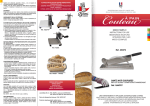
ENDURO STEEL
English
Español
ASSEMBLY INSTRUCTION
INSTRUCCIONES PARA EL ENSAMBLAJE
ENDURO STEEL
English
Before starting the assembly process, unpack all components of the staircase. Lay them out on a large surface and
check the quantity of all the pieces, by consulting the table TAB.1 (A = Code, B = Quantity).
Inside the staircase box you will also find a DVD which we suggest watching before proceeding to assemble.
For the USA only: call the customer support line at 1-888 STAIRKT, should you have any case of need.
Preliminary Assembly
1.
2.
3.
4.
Assemble the cylinders D32 into the treads (L02) by using the elements D33. Tighten by means of the article C36. Insert the elements C13 and C31 into the cylinders D32.(fig. 2)
Carefully measure the floor-to-floor height and determine the required number of spacers (D03) (TAB.2).
Assemble the spacers ( D14, D03, D02) together in one piece. Do the same for the spacers (D04, D03, D02).
Assemble the base G03, B17 and B46 (fig. 1).
Assembly
5. Determine and mark on the floor the fixing point of the base (G03+B17+B46) by laying the laning (E03) on the ceiling (fig. 3).
6. Place the base (G03+B17+B46) and drill with drill bit Ø 14 (fig. 3).
7. Fix the base (G03+B17+B46) onto the floor with the parts B13.
8. Screw the pole (G02) into the base (G03+B17+B46) (fig. 1).
9. Insert the base cover (D05) (fig. 4).
10.Insert the spacers (D14+D03+D02) (fig. 4).
11.Insert the first tread (L02) into the pole (G02). Then continue with the assembly, by adding alternatively one spacer (D04+D03+D02) and one tread (L02). At this stage, the treads have to be positioned alternately one to the right and one to the left, so as to distribute the weight in a balanced way (fig. 4).
12.When you reach the end of the pole (G02), screw the part B47 on it, then add the second pole (G02) and continue with the stair assembly (fig. 4)
13.When you reach the end of the pole (G02), screw on it the part B46 and the part G01 (screw the part G01, till its upper end sticks out approximately 15cm (6’’) from the stair height. Continue adding the treads, by using the part D01 inserted into the spacers (D04+D03+D02) (fig.5).
14.Finally add the stair landing (E03). Fasten the parts B05, B04 and screw the part B03 sufficiently, keeping in mind that the treads still have to rotate (fig. 1).
Fitting of the Landing
15.Drill with drill bit Ø 14 in relation to the holes.
16.Block the part B13 completely (fig. 1).
Assembly of the Railing
17.Spread-out the treads (L02) fan-like, after having chosen the rotation direction (fig. 6). It is now possible to use the stair.
18.Starting from the landing (E03), insert the first long railing baluster (C07): 1) measure the rise between the tread (L02) and the landing (E03) and add 2,5cm (1”), 2) cut the final part of the long baluster (C07), 3) pierce with the drill bit 9 the landing (E03), 4) assemble the parts F01 using the parts B44,B07 and B23, 5) insert the just cut baluster part between the lower part F01 and the tread (L02), 6) tighten the parts C31 of the tread and of the landing, 7) insert and fasten with the part C31 the resting part of the baluster (C07) into the upper part F01 (fig. 1).Turn the balusters (C07) maintaining the holes looking to the stair centre.
19.Insert the longer balusters (C07), which connect the treads (L02), one by one. Tighten only the part C31 of the lower tread (fig. 2).
20.Check the vertical position of all the assembled balusters (C07). This control is very important for best results.
21.Tighten securely the part B03 (fig. 6).
22.Tighten securely the part C31 of the upper tread (fig. 2).
23.Check once more the vertical position of the railing balusters (C07) and, if necessary, correct it, by repeating the previous operations.
25.Fix into the floor in relation to the first baluster (C07), the part F01, by piercing with the drill bit 8. Use the parts B11, B12, C29 and C31 (fig. 1).
25.Cut one long baluster (C07) to obtain the same size as all others you assembled previously (fig. 1).Set the first baluster (C07) together with the reinforcing part (C30).
26.Warm the handrail (A02) until it becomes malleable: 1) put the handrail onto the cover of the wooden box, 2) warm for about five minutes making circular movements continuously without holding on, 3) turn it on its other part and repeat that operation.
ENDURO STEEL
27.Set the handrail (A02) onto the balusters (C07) starting from the top before it becomes cold (fig. 6).
28.Drill the handrail (A02) in relation to the present holes and fasten with the parts B54 and B55.
29.Insert quickly all the other balusters, paying attention to their vertical position, into the treads (L02), tighten the part C31 and fasten to the handrail (A02) using the parts B54 and B55 (for the stairs with a diameter larger than 140cm (4’ 7 1/8”), it is advisable to assemble first the shorter balusters).
30.Cut the excess piece of the handrail (A02) in relation to the first railing baluster (C07).
31.Complete the handrail (A02) by assembling the parts A03. Use the glue (X01) (fig. 1).
32.Tighten the parts C31, D32 and D33 completely.
33.Complete the railing assembly inserting the parts B82 into the lower part of the balusters (C07) (fig. 1).
Assembly of the Balustrade
34.Screw the baluster (C04) into the part G01 that sticks out from the landing (E03) (fig. 1).
35.Fix the part B01 into the baluster (C04), by using the part C31 and some silicone (fig. 1).
36.Assemble the parts F01, using the parts B89, B27, B23 into the holes of the landing (E03), maintaining a similar distance as between the balusters (C07) of the railing, which had been assembled previously. (fig. 1).
37.Place the shorter balusters (C07) in part F01, applying some silicone in order to seal the space between the two elements and to tighten part C31.
38.Fix the handrail (A02), using the parts B54 and B55 (fig. 1).
39.In case that there are walls around the stair well and on their position, it could be necessary to position one or two more balusters.
40.In that case it is necessary to consider either the distance between all other balusters, or otherwise the distance from the wall. For the fixing it is suggested to pierce with a drill bit Ø 9 the landing (E03) and to use the fixing parts F01, C31, B89, B27, B23 (fig. 10).
Final Assembly
41.In order to re-inforce the staircase at the intermediate points, you must fix into the wall the parts F09 and connect them to the balusters (C07) by means of the parts F08. Pierce the wall with a drill bit 8 and use the parts B36,B37, B11, B12 (fig. 11).
42. Clean the surface of all the treads from eventual drosses of metal shavings which fell down during the drilling of the landing E03 (points 18 and 39) to avoid that there will be an evolvement of rust on the upper surface of the galvanization.
Characteristics of staircases for outdoors
Arkè products are made of excellent quality and treated with the best technological process; the staircase model
CIVIK ZINK, especially, has the following features:
stainless steel screws
• balusters made of pre-galvanized sheet with the addition of cold galvanizing on the welded joints.
• treads and landing are welded by a welding robot and they are hot-dip galvanized on 450°after degreasing • passivation in full respect of normative standards UNI E 14.07.000.0 and certification ISO 9002.
It’s a usual feature of the hot-galvanized products to present small areas in which the zinc
is not perfectly sticked.
It’s also possible to damage the galvanized surface during the assembly.
To guarantee a long life product, you will find a kit of liquid zinc in the box to lay on with a
brush for possible retouches after the assembly.
We suggest to check the wholeness of your staircase at regular intervals, and to retouch possible damaged areas
with similar products easily to be found on the market.
It’s a usual feature of the hot-galvanized products that they become matt after some time, that’s because of a
normal oxidation process of the zinc in all weather conditions.
The staircase may be painted immediately after a preventive application of a suitable primer or, without any
particular cautions, after an exposition to weather conditions of at least 12-18 months.
ENDURO STEEL
Español
Antes de empezar el ensamblado de la escalera, desembalar todas las piezas de la escalera. Colocarlas de
manera que pueda verificarse las cantidades (TAB. 1; (A = Código, B = Cantidad).
En el embalaje encontrareis un DVD que aconsejamos de ver antes de empezar.
Para el mercado de los EEUU, para cualquier duda, llamar al teléfono de asistencia clientes 1-888 STAIRKT.
Ensamblaje previo
1.
2.
3.
4.
Ensamblar los cilindros roscados D32 en los peldaños (L02) con el elemento D33. Apretar con el artículo C36. Introducir los elementos C13 y C31 en los cilindros roscados D32. (fig. 2)
Medir cuidadosamente la altura de pavimento a pavimento para determinar la cantidad de discos distanciadores (D03) (TAB.2)
Montar entre sí los distanciadores (D14, D03, D02). Montar de la misma manera los distanciadores (D04, D03, D02).
Montar la placa base G03, B17 y B46 (fig. 1)
Ensamblaje
5. Hallar el punto donde fijar la placa de base sobre el pavimento (G03 + B17 + B46) presentando la meseta (E03) en el forjado (fig. 3).
6. Colocar la base (G03 + B17 + B46) y taladrar con una broca de Ø 14 (fig. 3)
7. Fijar definitivamente la base (G03 + B17 + B46) con los elementos B 13.
8. Atornillar el tubo (G02) a la base (G03 + B17 + B46) (fig. 1)
9. Introducir el cubre placa (D05) (fig. 4)
10.Introducir los distanciadores (D14 + D03 + D02) (fig. 4)
11.Introducir el primer peldaño (L02) por el tubo (G02). Seguir introduciendo por orden un distanciador (D04 +
D 03 + D02) y el siguiente peldaño (L02) u así sucesivamente. Ir colocando los peldaños alternativamente a derecha e izquierda, para distribuir, así el peso uniformemente.
12.Alcanzado el extremo del tubo (G02), atornillar el elemento B47, atornillar el tubo (G02) siguiente y seguir ensamblando la escalera (fig. 4)
13.Alcanzado el extremo del tubo (G02), atornillar el elemento B46 y el elemento G01 (atornillar el elemento G01 teniendo en cuenta que debe sobrepasar la altura de la escalera de unos 15 cm (6”). Seguir introduciendo los peldaños utilizando el elemento D01 introducido en el distancial (D14 + D03 + D02) (fig. 4)
14.Introducir la meseta (E03). Introducir los elementos B05, B04 y apretar el elemento B03 suficientemente, teniendo en cuenta que los peldaños deben poder moverse (fig. 1)
Fijación de la meseta
15.Taladrar con una broca de Ø14 coincidiendo con los orificios
16.Fijar definitivamente el elemento B13 (fig. 1)
Ensamblaje de la barandilla
17.Abrir los peldaños (L02) en abanico, tras haber elegido el sentido de rotación (fig. 6). Ahora es posible subir por la escalera.
18.Empezar por la meseta (E03) adaptar el primer barrote largo (C07): 1) medir la altura entre el peldaño (L02) y la meseta (E03) y añadir 2,5 cm (1”), 2) cortar la parte final del barrote largo (C07), 3) taladrar con una broca de Ø 9 la meseta (E03), 4) montar los elementos F01 utilizando los elementos B44, B07 y B23, 5) introducir el trozo de barrote recién cortado entre el elemento F01 inferior y el peldaño (L02), 6) Apretar los elementos C31 del peldaño y de la meseta, 7) introducir y fijar con el elemento C31 el resto del barrote (C07) en el elemento F01 superior (fig. 1). Orientar el barrote (C07) manteniendo los orificios hacia el centro de la escalera.
19.Introducir sucesivamente los barrotes más largos (C07) de unión entre los peldaños (L02). Apretar solamente el elemento C31 del peldaño inferior.
20.Comprobar la verticalidad de todos los barrotes (C07) colocados. Tener mucho cuidad en este paso porqué es muy importante para tener un buen resultado del montaje.
21.Apretar definitivamente el elemento B03 (fig. 6).
22.Apretar definitivamente los elementos C31 de los peldaños superiores.
23.Volver a controlar la verticalidad de los barrotes (C07) y corregirla, si fuera necesario, repitiendo las operaciones anteriores.
24.Fijar sobre el pavimento, coincidiendo con el primer barrote (C07), el elemento F01, taladrando con una broca de Ø 8. Utilizar los elementos B11, B12, C29 y C31 (fig.1)
25.Adaptar la altura de un barrote largo(C07), cortando un extremo, a la altura de los barrotes recién ensamblados ENDURO STEEL
(fig. 1).Colocar el primer barrote (C07) junto con el elemento de refuerzo (C30).
26.Calentar el pasamanos (A02) hasta lograr que sea moldeable: 1) colocar el pasamanos sobre la tapa de la caja de madera, 2) calentar durante unos cinco minutos con movimientos circulares sin detenerse, 3) voltear el pasamanos y repetir la operación (fig. 8)
27.Colocar el pasamanos (A02) sobre los barrotes (C07) empezando desde lo alto, antes de que se enfríe (fig. 6)
28.Taladrar el pasamanos (A02) en coincidencia de los orificios y fijar con los elementos B54 y B55.
29.Colocar los demás barrotes, teniendo cuidado con su verticalidad, en los peldaños (L02), apretar el elemento C31 y fijar al pasamanos (A02) utilizando los elementos B54 y B55 (para los modelos de diámetro superior a 140 cm (4’7 1/8”), aconsejamos montar antes los barrotes más cortos).
30.A la altura del primer barrotes (C07) de la escalera, cortar el pasamanos (A02) en exceso.
31.Completar el pasamanos (A02) fijando los elementos A03, utilizando el pegamento (X01) (fig. 1)
32.Apretar los elementos C31, D32 and D33 definitivamente.
33.Completar el montaje de la barandilla, introduciendo los elementos B82 de la parte inferior de los barrotes (C07) (fig. 1)
Montaje de la balaustrada
34.Atornillar la columna (C04) al elemento G01 que asoma de la meseta (E03) (fig. 1).
35.Fijar el elemento B01 sobre la columna (C04) utilizando el elemento C31 y silicona (fig. 1)
36.Montar los elementos F01, utilizando los elementos B89, B27 y B23 en los orificios presentes en la meseta (E03), manteniendo una distancia entre ejes similar a la presente entre los barrotes (C07) de la barandilla ensamblada anteriormente (fig. 1).
37.Colocar el barrote más corto (C07) en los elementos F01, aplicando un poco de silicona para sellar el espacio entre los dos elementos y apretar e elemento C31.
38.Fijar el elemento B01 sobre la columna (C04) utilizando el elemento C31 y silicona (fig. 1).
39.Según la posición y de la presencia de paredes alrededor del hueco de la escalera podría ser necesario colocar uno o dos barrotes más (fig. 9).
40.En este caso es necesario considerar un espacio equidistante entre los demás barrotes y la pared. Para la fijación es recomendable taladrar la meseta (E03) con una broca Ø 9 y utilizar los elementos F01, C31, B89, B27, B23 (FIG. 10).
Montaje final
41.Para darle mayor rigidez a la escalera en los puntos intermedios, fijar al muro los elementos F09 y unirlos, utilizando los elementos F08, con los barrotes (C07). Taladrar con una broca de Ø 8 y utilizar los elementos B36m B37, B11, B12 (fig. 11).
42. Limpiar la superficie de todos los peldaños de posible residuos, viruta metálica, caída durante el taladrado de la meseta E03 (punto 18 y 39) con el fin de evitar la aparición precoz de oxido sobre la superficie galvanizada.
Características de la escalera para exterior
Los productos ARKE’ están construidos con componentes de primera calidad y tratados con los mejores procesos
tecnológicos; particularmente el modelo CIVIK ZINK presenta las siguientes características:
• Tornillería de acero inoxidable.
• Barrotes de chapa pregalvanizada con ulterior aportación de zinc en frio en la soldadura de unión.
• Peldaños y Meseta soldados con procesos robotizados y galvanizados por inmersión en zinc fundido a 450º,
tras ser desengrasados según las normas UNI E 14.01.000.0 y en la certificación ISO 9002.
Es característica de los productos galvanizados en caliente presentar en pequeñas zonas donde la adhesión del
zinc no es perfecta.
También es posible dañar la superficie galvanizada durante la colocación.
Para garantizar una larga duración del producto, se incluye en el suministro un bote de zinc liquido, para aplicar
con brocha, para posibles retoques tras la colocación.
Aconsejamos verificar periódicamente la integridad de la escalera retocando eventuales puntos dañados con
productos análogos, presentes en el mercado.
Es característica de los productos galvanizados en caliente volverse mates con el tiempo, debido a un proceso
normal de oxidación del zinc expuesto a los agentes atmosféricos.
Es posible pintar la escalera justo tras el montaje utilizando una imprimación apta, o bien, sin ninguna
preocupación, tras tener expuesta la escalera a los agentes atmosféricos durante unos 12-18 meses.
ENDURO STEEL
TAB 1
A
A02
A03
B01
B03
B04
B05
B11
B12
B13
B17
B23
B27
B36
B37
B44
B46
B47
B54
B55
B82
B89
C04
C07
C13
C29
C30
C31
C36
D01
D02
D03
D04
D05
D14
D32
D33
E03
F01
F08
F09
G01
G02
G03
L02
X02
B
Ø 120
Ø 140
Ø 160
3' 11 1/4"
4' 7 1/8"
5' 3"
1
8
1
1
1
1
7
7
6
1
8
8
2
2
1
2
1
30
30
25
7
1
32
36
1
1
50
1
4
13
65
12
1
1
36
36
1
10
2
2
1
2
1
12
1
1
8
1
1
1
1
7
7
6
1
9
9
2
2
1
2
1
43
43
38
8
1
45
48
1
1
63
1
4
13
65
12
1
1
48
48
1
11
2
2
1
2
1
12
1
1
8
1
1
1
1
10
10
6
1
10
10
3
3
1
2
1
44
44
38
9
1
46
48
1
1
64
1
4
13
65
12
1
1
48
48
1
12
3
3
1
2
1
12
1
ENDURO STEEL
ENDURO STEEL
English
To determine the necessary number of spacers (D03), you must look-up the table TAB.2 (H = Height, A = Rises).
Example: given a floor-to-floor height of 298cm (9' 9 3/8") and a staircase with 13 treads, you must proceed as
follows;
1. At height (298cm (9' 9 3/8") in the row H) look-up the number of necessary spacers (i.e. 50 spacers in the row
A/13)
2. Distribute the spacers (D03), one at a time, among the combined parts D14-D04 and D02 all (for the single
spacer D14 you can use at the most 3 spacers (D03); for the spacers (D04) you can use at the most 5 spacers
(D03).
3. The final result is the following: 3 spacers (D03) between D14 and D02, 3 more spacers (D03) on a spacer
chosen between D04 and D02 and 4 spacers (D03) between D04 and D02 of the remaining eleven spacers.
Español
Para determinar la cantidad necesaria de discos distanciadores (D03) utilizar la TABLA 2 (H = altura, A = tabicas)
Ejemplo: para una altura de pavimento a pavimento de 298 cm (9' 9 3/8") y una escalera con 13 peldaños es
necesario;
1. En la línea de la altura (298 cm (9' 9 3/8"), en la columna H), leer la cantidad de discos distanciadores
necesarios (nº 50 discos, en la columna A/13).
2. Distribuir los discos distanciadores (D03), entre los elementos D14, D04 y D02 uno a la vez, hasta agotarlos
(en el único distanciador D14 pueden introducir un máximo de 3 discos (D03); en los distanciadores D04
pueden introducirse un máximo de 5 discos (D03).
3. .El resultado es de 3 discos (D03) entre D14 y D02, otros 3 discos (D03) en un distanciador cualquiera entre
D04, D02 y 4 discos (D03) entre D04 y D02 en los once distanciadores que quedan.
ENDURO STEEL
TAB 2
A
A
H
10
6'
6'
6'
6'
7'
7'
7'
7'
7'
7'
7'
7'
7'
7'
7'
7'
7'
7'
7'
7'
7'
7'
7'
7'
7'
7'
7'
7'
7'
7'
7'
7'
7'
7'
8'
8'
8'
8'
8'
8'
8'
8'
8'
8'
8'
8'
8'
8'
8'
8'
8'
8'
8'
8'
8'
8'
8'
8'
8'
8'
8'
8'
8'
8'
10
11
11
11
1
1
1
2
2
3
3
3
4
4
5
5
5
6
6
7
7
7
8
8
8
9
9
10
10
10
11
11
1
1
2
2
2
3
3
4
4
4
5
5
6
6
6
7
7
8
8
8
9
9
9
10
10
11
11
A
H
5/8"
1/8"
1/2"
7/8"
1/4"
5/8"
"
3/8"
7/8"
1/4"
5/8"
"
3/8"
3/4"
1/4"
5/8"
"
3/8"
3/4"
1/8"
1/2"
"
3/8"
3/4"
1/8"
1/2"
7/8"
1/4"
3/4"
1/8"
1/2"
7/8"
1/4"
5/8"
1/8"
1/2"
7/8"
1/4"
5/8"
"
3/8"
7/8"
1/4"
5/8"
"
3/8"
3/4"
1/8"
5/8"
"
3/8"
3/4"
1/8"
1/2"
"
3/8"
3/4"
1/8"
1/2"
7/8"
1/4"
3/4"
1/8"
1/2"
0
2
4
6
8
10
12
14
16
18
20
22
24
26
28
30
32
34
36
38
40
42
44
46
48
50
11
0
2
4
6
8
10
12
14
16
18
20
22
24
26
28
30
32
34
36
38
40
42
44
46
48
50
52
54
8'
8'
8'
8'
8'
8'
8'
8'
8'
8'
8'
8'
8'
8'
8'
8'
8'
8'
8'
8'
8'
8'
8'
9'
9'
9'
9'
9'
9'
9'
9'
9'
9'
9'
9'
9'
9'
9'
9'
9'
9'
9'
9'
9'
9'
9'
9'
9'
9'
9'
9'
9'
9'
10'
10'
10'
10'
10'
10'
10'
10'
10'
10'
10'
3
3
4
4
4
5
5
6
6
6
7
7
8
8
8
9
9
9
10
10
11
11
11
1
1
1
2
2
3
3
3
4
4
5
5
5
6
6
7
7
7
8
8
8
9
9
10
10
10
11
11
1
1
2
2
2
3
3
4
A
H
1/4"
5/8"
"
3/8"
3/4"
1/8"
5/8"
"
3/8"
3/4"
1/8"
1/2"
"
3/8"
3/4"
1/8"
1/2"
7/8"
1/4"
3/4"
1/8"
1/2"
7/8"
1/4"
5/8"
"
1/2"
7/8"
1/4"
5/8"
"
3/8"
7/8"
1/4"
5/8"
"
3/8"
3/4"
1/8"
5/8"
"
3/8"
3/4"
1/8"
1/2"
7/8"
3/8"
3/4"
1/8"
1/2"
7/8"
1/4"
3/4"
1/8"
1/2"
7/8"
1/4"
5/8"
"
1/2"
7/8"
1/4"
5/8"
"
12
KIT
0
2
4
6
8
10
12
14
16
18
20
22
24
26
28
30
32
34
36
38
40
42
44
46
48
50
52
54
56
58
60
H
13
0
2
4
6
8
10
12
14
16
18
20
22
24
26
28
30
32
34
36
38
40
42
44
46
48
50
52
54
56
58
60
62
64
14
9'
9'
9'
9'
9'
9'
9'
9'
9'
9'
9'
10'
10'
10'
10'
10'
10'
10'
10'
10'
10'
10'
10'
10'
10'
10'
10'
10'
10'
10'
10'
10'
10'
10'
10'
10'
10'
10'
10'
10'
10'
10'
11'
11'
11'
11'
11'
11'
11'
11'
11'
11'
11'
11'
11'
11'
11'
11'
11'
11'
11'
11'
11'
11'
7
8
8
8
9
9
10
10
10
11
11
1
1
2
2
2
3
3
4
4
4
5
5
6
6
6
7
7
8
8
8
9
9
9
10
10
11
11
11
1
1
1
2
2
3
3
3
4
4
5
5
5
6
6
7
7
7
8
8
ENDURO STEEL
3/4"
1/8"
1/2"
7/8"
3/8"
3/4"
1/8"
1/2"
7/8"
1/4"
3/4"
1/8"
1/2"
7/8"
1/4"
5/8"
"
1/2"
7/8"
1/4"
5/8"
"
3/8"
3/4"
1/4"
5/8"
"
3/8"
3/4"
1/8"
1/2"
"
3/8"
3/4"
1/8"
1/2"
7/8"
3/8"
3/4"
1/8"
1/2"
7/8"
1/4"
5/8"
1/8"
1/2"
7/8"
1/4"
5/8"
"
3/8"
7/8"
1/4"
5/8"
"
3/8"
3/4"
1/4"
5/8"
"
3/8"
3/4"
1/8"
1/2"
0
2
4
6
8
10
12
14
16
18
20
22
24
26
28
30
32
34
36
38
40
42
44
46
48
50
52
54
56
58
60
62
64
66
68
70
15
0
2
4
6
8
10
12
14
16
18
20
22
24
26
28
30
32
34
36
38
40
42
44
46
48
50
52
54
56
58
60
62
64
66
68
70
72
74
16
11'
11'
11'
11'
11'
11'
11'
11'
11'
11'
11'
11'
11'
11'
11'
11'
11'
11'
11'
11'
11'
11'
11'
11'
11'
11'
11'
11'
11'
11'
12'
12'
12'
12'
12'
12'
12'
12'
12'
12'
12'
12'
12'
12'
12'
12'
12'
12'
12'
12'
12'
12'
12'
12'
12'
12'
12'
12'
12'
12'
12'
13'
13'
13'
1
1
1
2
2
3
3
3
4
4
5
5
5
6
6
7
7
7
8
8
9
9
9
10
10
10
11
11
1
1
2
2
2
3
3
4
4
4
5
5
6
6
6
7
7
8
8
8
9
9
10
10
10
11
11
11
1
1/4"
5/8"
1/8"
1/2"
7/8"
1/4"
5/8"
"
3/8"
7/8"
1/4"
5/8"
"
3/8"
3/4"
1/4"
5/8"
"
3/8"
3/4"
1/8"
1/2"
"
3/8"
3/4"
1/8"
1/2"
7/8"
1/4"
3/4"
1/8"
1/2"
7/8"
1/4"
5/8"
1/8"
1/2"
7/8"
1/4"
5/8"
"
3/8"
7/8"
1/4"
5/8"
"
3/8"
3/4"
1/8"
5/8"
"
3/8"
3/4"
1/8"
1/2"
10"
3/8"
3/4"
1/8"
1/2"
7/8"
1/4"
3/4"
1/8"
0
2
4
6
8
10
12
14
16
18
20
22
24
26
28
30
32
34
36
38
40
42
44
46
48
50
52
54
56
58
60
62
64
66
68
70
72
74
76
78
80
FIG. 1
ENDURO STEEL
FIG. 2
FIG. 3
FIG. 4
FIG. 5
ENDURO STEEL
FIG. 5 A
ENDURO STEEL
FIG. 6
FIG. 8
FIG. 9
FIG. 10
FIG. 11
ENDURO STEEL
English
PRODUCT DETAILS
Español DATOS DE IDENTIFICACIÓN
6
7
4
1
5
3
2
ENDURO STEEL
GB)
product details
trade name: enduro steel
type: spiral round plan staircase
used materials
STRUCTURE
description
composed by spacers (1) in metal (welded to the tread)
and spacers (2) in plastic stacked and packed on the central modular pole (3)
materials
spacers: Fe 370
plastic spacers: nylon 66
pole: Fe 370 galvanized
finishing
spacers: hot galvanized
TREADS
description
treads (4) in metal circular stacked on the central pole (3)
materials
treads: plate Fe 370 thickness 25/10
finishing
hot galvanized
RAILING
description
composed by vertical balusters (5) in metal fixed to the treads (4) and by a PVC handrail (6)
materials
balusters: Fe 370
handrail: PVC
fixings (7): nylon
finishing
balusters: hot galvanized
CLEANING
clean with a soft wet cloth, without any product containing solvents or abrasive materials.
MAINTENANCE
about 12 months after the installation date, check the tightening of bolts on the various components. all non-routine
maintenance procedures must be carried out in a strictly professional manner.
USE PRECAUTION
avoid any improper use that is not in accordance with the product. possible violations or installations which don’t
comply with the providers instructions can invalidate the agreed product conformities.
ENDURO STEEL
E)
datos de identificación del producto
denominación comercial: ENDURO STEEL
tipo: escalera de caracol de planta redonda
materiales empleados
ESTRUCTURA
descripción
compuesta por distanciadores (1) de metal (soldados al peldaño) y riostras (2) de plástico enfiladas y
comprimidas en la columna (3) central modular
materiales
distanciadores: Fe 370
riostras: nylon 66
columna central: Fe 370 galvanizado
acabado
distanciadores: galvanización en caliente
PELDAÑOS
descripción
peldaños (4) de metal circulares enfilados en la
columna (3) central
materiales
peldaños: chapa Fe 370 grosor 25/10
acabado
galvanización en caliente
BARANDILLA
descripción
compuesta por barrotes (5) verticales de metal fijados a los peldaños (4) y por un pasamanos (6) de PVC
materiales
barrotes: Fe 370
pasamanos: PVC
fijaciones (7): nylon
acabado
barrotes: galvanización en caliente
LIMPIEZA
limpiar con un trapo suave humedecido con agua y sin ningún producto que contenga disolventes o materiales abrasivos.
MANTENIMIENTO
transcurridos unos 12 meses desde la fecha de instalación, comprobar que los tornillos que fijan las distintas partes sigan
bien apretados. el mantenimiento extraordinario debe ser efectuado como corresponde.
PRECAUCIONES DE USO
evitar usos impropios y no conformes con el producto. eventuales manipulaciones o instalaciones que no cumplan con
las instrucciones del fabricante pueden menoscabar las cualidades certificadas en las pruebas de conformidad a las que
previamente fue sometido el producto.
ENDURO STEEL
For further information pertaining to these assembly instructions, additional parts or general
questions regarding products or assembly please call, fax or email us at:
ARKE' by Fontanot
Albini & Fontanot SpA
75 Jackson Street, Suite 303
Newnan, GA 30263
Toll Free: (888) 782 - 4758
Phone: (770) 683 - 7200
Fax: (770) 683 - 7209
Email: [email protected]