1
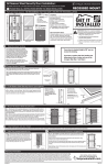
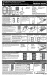
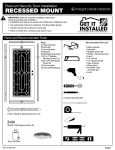
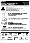
Premium Security Double Door Installation SURFACE MOUNT IMPORTANT: Read the complete installation instructions before proceeding with installation. • • • • Installation may require two people when lifting and installing the doors Use appropriate protective equipment, including safety glasses Children should not be allowed in work area Failure to install doors correctly could result in injury Ask an Associate for Details Parts and Recommended Tools E C K A B F G H I O M D P N L Parts: A) Hinge Left Jamb Assembly B) Hinge Right Jamb Assembly C) Door Slab - Inactive D) Door Slab - Active E) Top/Head Jamb F) Multi-blade Bug Sweep - Left G) Multi-blade Bug Sweep - Right H) Threshold Plate - Left I) Threshold Plate - Right J) Bottom Bar Assembly K) Touch-up Paint L) One-Way Driver Tool M) 4" One-way Screws (12 pcs.) N) #10 3-1/2" Drywall Screws (6 pcs.) O) #8 (16 pcs.) Black Self-tapping screws P) (2 pcs.) 6" x 36" Cardboard Threshold Templates Recommended Tool List: Measuring Tape Pencil Level Drill and Drill Bits (1/8", 5/32", 3/16") Flat-blade Screwdriver Power Drill w/Phillips Bit (Battery or Electric) Square Tin-snips/aviator snips Box Knife Safety Glasses 2x4 Wood Blocks 1x3 Wood Blocks Wood Shims Caulk and Caulk Gun J 1 Determining Your Build Out Area Inspect Your Entryway for Obstructions Check for any obstructions above and around your entryway that may prevent the outward swing of your new security doors and/or their installation, such as: Light fixtures Door bell Low overhang Determine Type and Readiness of Mounting Surface Your new double security doors will require a minimum mounting surface of 1" on the trim above and on both sides of your entry door. Mounting screws must be secured to a stud in the wall. Review the diagrams below and determine which one most resembles the trim around the entry door to which you will mount your double security doors. Door handle of your existing entry door Trees, bushes or hanging plants Brick Molding (Top View) Stud Entry Door Entry Door Jamb Flat Trim (Top View) Stud Stud Entry Door Brick molding trim 1" minimum mounting surface Ready for installation Flat Trim 1" minimum mounting surface 1" minimum mounting surface or Stud Entry Door Jamb Ready for installation 1" minimum mounting surface or Stucco 1 (Top View) Entry Door Stud Entry Door Jamb Sloped Trim (Top View) Stud Stucco Pop-Out Stud Entry Door Stud Entry Door Jamb Sloped Trim* 1" minimum mounting surface Ready for installation Mounted between stucco pop-outs 1" minimum mounting surface or Stucco 2 (Top View) Stud 1" minimum mounting surface 09212012 Entry Door Entry Door Jamb This application will require 6" screws (Sold separately) mounted to front surface of stucco pop-outs Stud Stucco Pop-Out 1" minimum mounting surface MK616 2 Determining Your Threshold Configuration Look at your existing entry door threshold and use the diagrams below to determine which threshold configuration best applies to your entryway. This will determine whether a bottom bar is or is not required for your double security doors. Bottom Bar Required 3 Bottom Bar NOT Required The concrete is set back and lacks space to mount to the threshold plate. The concrete extends at least 7/8" further than your trim. The concrete and threshold sets back behind the trim. The existing threshold extends beyond the trim by 7/8" or more. The existing threshold sticks out beyond the trim by 3/16" or less. The existing threshold extends past the trim between 3/16" and 7/8". Preparing Your Security Door Glass Removal Handleset Attachment If your doors include glass, remove it before you start the installation procedure. Loosen (do not remove) each screw. Carefully hold the glass panel in place and rotate each clip 90°. Carefully remove the glass panel and store it in a safe place during installation. 4 Rotate 90° clips Attach your choice of locksets with 2-3/8" backset (Sold separately.) Fully extend the lock bolts into the "locked" position on the handle side of the security door (D). Installing the Inactive-side Jamb Mounting the Inactive-side Jamb 3 This side up Note: verify that direction of hinge pins match illustration Position hinge-side jamb assembly (A) on the inactive-side of the double doors. Allow for a 1/8" gap between the hinge-side edge of jamb and inside-edge of your mounting surface. 1 Note: There should be a minimum of 2-3/4" space below the hinge side jamb and below the entire width of the door to allow space for the bottom bar (attached in Step 10). It is okay to move the doors up within the doorway to ensure this space, as long as the top of the jambs do not go beyond the top edge of your trim framing. If a 2- 3/4" space exists across the entire doorway, skip to step 5. Otherwise, position bottom bar assembly (J) on the ground in front of the doorway with the legs pointing up. Position the hinge-side jamb assembly (A) on the inactive side of the double doors sliding the jamb over the bottom bar leg to correctly position the jamb. This alignment will be repeated for the active side jamb. A 2 4 J Insert bottom bar into jamb Important: All jambs must be positioned to allow secure mounting to your trim framing around the opening. Make certain the jamb assembly is plumb, and mark the location of the mounting holes with a pencil. Set the jamb aside and, where marked, pre-drill 3/16" holes. Support inactive jamb with temporary screws: Drive two of the #10 3-1/2" drywall screws (N) supplied into the middle holes (1 & 2 in the diagram on left) for the inactive-side jamb (A). These screws are inserted only to hold the security door frame plumb and will be removed and replaced in step 9. 5 Installing the Top/Head Jamb E A Place the top head jamb (E) above the side jamb (A). Take care to make sure that a minimum of 1/8" reveal is consistent on side jamb (A) as well as on the top head jamb (E). Spacing should be equal, from left to right, and above the door. Mark the location of the mounting holes. Set the top head jamb (E) aside and, where marked, pre-drill 3/16" holes 1-1/4" inches deep. Return top head jamb to position and fasten to mounting surface using the provided one-way screws (M) and the supplied one-way driver tool (L). MK616 6 Installing the Active-side Jamb Mounting the Active-side Jamb E 3 Position active-side jamb assembly (B) on the active side of the double doors. Allow for a 1/8" gap between the hinge-side edge of jamb and inside-edge of your mounting surface. Note: If the bottom bar has been placed under the door, slide the jamb over the bottom bar leg refer to step 4. Important: All jambs must be positioned to allow secure mounting to your trim framing around the opening. 1 B A 2 Make certain the jamb assembly is plumb, and mark the location of the mounting holes with a pencil. Set the jamb aside and, where marked, pre-drill 3/16" holes. Support active jamb with temporary screws: Drive two of the #10 3-1/2" dry wall screws (N) supplied into the middle holes (1 & 2 in the diagram on right) for the active-side jamb (B). These screws are inserted only to hold the security door frame plumb and will be removed and replaced in step 9. 7 This side up Note: verify that direction of hinge pins match illustration 4 Hang the Doors to Test Fit C E Door-side (D) hinge D A Leveling washers B Hang the security doors (C & D) on the jamb hinges (A & B), holding the doors open at more than a 90° angle (see diagram at right), starting with the bottom pin first. Top View A C More than 90° B More than 90° D Jamb-side (B) hinge 8 Lock Alignment Hinge side Lock side Gap between doors (C & D) and both side jambs (A & B) should appear equal on each side with a minimal reveal of 1/8", up to 1/4". Test the alignment of the lock bolts with the lock holes by closing both door panels and extending the bolts. Note: the bolt should slide easily in and out of the hole and be somewhat centered. If the bolts do not align properly with the holes, measure the distance, up or down, of the misalignment. Retract the bolts and remove the lock side door panel from the hinges. Set aside. Remove temporary screws (N) from the active side jamb, adjust the height as measured, and reinstall jamb with temporary screws. Hang the door back on the hinges and retest lock fit. If necessary, repeat until properly aligned. NOTE: Rubber shims are preattached to inactive-side door and at the tops of doors to ensure proper reveal. Use these as reference. 9 Lock Alignment Secure Jambs E 3 1 A Secure Inactive-side Jamb with One-way Screws: Drill two 5/32" diameter holes 3" deep into the entryway trim mounting surface through holes 3 & 4 in the inactive-side jamb (A). Drive the ¼" diameter one-way screws (M) through holes 3 & 4 into the entryway trim mounting surface using your drill and the supplied one-way driver tool (L). B 2 4 This side up Note: verify that direction of hinge pins match illustration Remove the two #10 3-1/2" dry wall screws (N) installed in the in-active side jamb (1 & 2 in the diagram) and drill two 3/16" diameter holes 3" deep into the entryway trim mounting surface through holes 1 & 2. Drive two ¼" diameter one-way screws (M) into holes 1 & 2 using your drill and the supplied one-way driver tool (L). Use a level at the top and bottom of the jamb (A) to make sure the jamb is level. Secure active-side jamb with one-way screws: Drill two 5/32" diameter holes 3" deep into the entryway trim mounting surface through holes 3 & 4 in the active-side jamb. Drive the ¼" diameter one-way screws (M) through holes 3 & 4 into the entryway trim mounting surface using your drill and the supplied one-way driver tool (L). Remove the two #10 3-1/2" dry wall screws (N) installed in the active-side jamb (1 & 2 in the diagram) and drill two 3/16" diameter holes 3" deep into the entryway trim mounting surface through holes 1 & 2. Drive two ¼" diameter one-way screws (M) into holes 1 & 2 using your drill and the supplied one-way driver tool (L). Use a level at the top and bottom of the jamb (B) to make sure the jamb is level. MK616 10 Installing the Bottom Bar Note: If you will NOT be installing the bottom bar, discard the bottom bar and skip to step 11. This step is easier if both door panels are removed from the hinges. Bottom Bar Placement Bottom Bar Installation The bottom bar (J) will need to be installed 1/8" to 1/4" lower than the Insert bottom bar into the left and right door jambs. Adjust the bottom bar (J) to the existing doorway so that there is slope to the threshold. This allows correct height. Using the predrilled holes in the center of each jamb (approximately any moisture to drain away from the door. 5/16" up from the bottom), install the bottom bar (J) using four #8 self-tapping screws (O). Keep the drill on a low speed so the threads do not strip out. J 11 Threshold Plate Installation Threshold Template Fitting 1 The contour of door framing varies, making it necessary to cut the threshold plate (H) to fit. We recommend using the provided cardboard template (P) to fit the opening first, to avoid cutting the threshold plate incorrectly. 2 Measure the widest portion of the doorway (usually the front edge). Divide this number by two. Cut both cardboard template pieces to this length. 3 Lay one of the provided cardboard templates (P) on top of the bottom bar, slide completely to one side, and push into existing threshold, as far as it will go. Using a straight edge, mark the template at the various widths of your existing molding and trim, at both ends. 4 Move template so that front edge is flush to the front edge of bottom bar (it is okay to bend to allow to fit the shortest width between your molding and trim). Mark at the various corners of your existing molding and trim. 5 Using a box knife, cut template to shape of molding and trim revealed by the markings. Test fit the template. (It should lay across the bottom bar, with the front edge flush with the front edge of the bottom bar and fit in and around the corners of the existing molding and trim). 6 Using the second cardboard template, repeat Steps 3 thru 5 for the opposite side of the doorway. 7 Once you have created a good fitting template, use the template to mark the threshold plate. 8 Note: Each half of the threshold plate has a half circle cut into the center of one end. These are the midpoint and should butt against each other to form the entire threshold plate. Overlay the cardboard temples with their straight ends butted together in the center. Align the cardboard template and the threshold plates along the center seams. 9 Mark each end of the threshold to match the corresponding template. 10 Using tin-snips/aviator snips, cut threshold plate to match the shape of template (6). Position threshold plate to extend across the bottom bar and into the existing threshold. Use 1/8" drill bit to pre-drill holes for mounting screws. Attach threshold plate to existing threshold using the provided screws (O). 1 2 Make cardboard templates Existing door contour 6 7 Place template on threshold 12 3 Fit template to contour 8 Repeat Steps 3-5 Butt threshold plates together 4 5 Template flush with bottom bar 9 Cut template to contour 10 Mark threshold plate Cut threshold plate to fit Installing the Doors C E Door side (D) hinge D A B Leveling washers Hang the security doors (C & D) on the jamb hinges (A & B), holding the door open at more than a 90° angle (see diagram below), starting with the bottom pin first. C F H G I Top View A More than 90° B More than 90° D Jamb side (B) hinge MK616 13 Installing the Bug Sweeps Open one side of the door. Slip the left multi-blade bug sweep (F) onto the bottom of the door. Hold sweep in place and close the door. Allow the sweep to fall and sit rested on the left threshold plate (H). Note: Be sure there is not a gap between the sweep and the threshold plate, and that the sweep is centered on the bottom of the door. Use 1/8" drill bit to pre-drill the two outer holes for mounting screws. Attach the sweep to the bottom of the door, by the two outer holes, using the provided #8 black self-tapping screws (O). Test that the door opens and closes freely. If not, loosen the screws and make necessary adjustments. Retighten screws and test again. Repeat until successful. Pre-drill remaining holes and install the rest of the provided #8 black-self tapping screws (O). Repeat this step for the other side of the door. 14 Installing the Door Closer and Wind Chain (Optional, purchased separately) Follow the manufacturer’s instructions included with the windchain and door closer to install the windchain and door closer on your new security door. Note: It is not required to use a windchain and door closer for your security door. 15 Final Touch Up and Upkeep Suggestions 1 Caulk (not included) 2 Touch-Up Paint (K) Shake the supplied touch-up paint (K) vigorously for 2 minutes and paint the heads of the one-way screws as indicated in the diagram. Caulk around the outside of the security door jamb frame using paintable caulk and paint to the desired color. 3 White Grease Lubricant (not included) Use white grease to lubricate the hinges of your new security door every six months. Paintable caulk & gun Warranty Information Your Unique Home Designs Premium Security Screen door is warranted for residential installations against manufacturer defects under normal use for as long as you own your UHD product, and terminates if you sell or otherwise transfer the product or the property upon which it was installed. The Powder Coat Finish is warranted for five years from date of purchase. All other components of the product, including sunscreen material, bug sweeps, weather-stripping, and composite materials are covered for one year from date of purchase. If the door breaks or structural defects occur, Unique Home Designs will, at our discretion, repair or replace the door. If your home is burglarized and entry was accomplished through a UHD security door, locked with a double dead bolt, UHD will pay your insurance deductible up to $1000 or replace as applicable the damaged UHD security door at no charge (the "Home Protection Warranty"). Replacement items may vary in style due to changes in suppliers and product. Not all colors can be reproduced if colors have been discontinued. UHD is not responsible for any labor expense required to repair or replace the door. UHD is not responsible for securing the property while warranted items are being repaired or replaced. Cutting parts not specified by the installation guide or parts drilled incorrectly are not included in this warranty. Any problem caused by abuse, misuse, failure to maintain warranted item properly, adjustments due to settling of the structure that the product is mounted on, or acts of God, are not covered. To make a claim under this Warranty, send a brief written description of the problem, a picture of the claim, proof of purchase, and your contact information to: Unique Home Designs, 973 N. Colorado Street, Gilbert AZ. 85233 Attn: Warranty Claims MK616