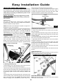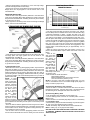
1
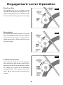
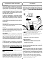
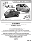
$2.00
REV 5/15/00
OWNER’S MANUAL
DX
ZAP POWER SYSTEM
MADE IN THE USA
Patent #5,491,390 #5,671,821 • Other Patents Pending
ZAPWORLD.COM
where transportation is going
One ZAP Drive •117 Morris Street • Sebastopol
California 95472 U.S.A.
tel (707) 824-4150 • fax (707) 824-4159
e-mail: [email protected] • Stock Symbol:ZAPP
©2001 ZAPWORLD.COM. All Rights Reserved. ZAP ® is a registered trademark.
YOUR INSURANCE POLICIES
MAY NOT PROVIDE COVERAGE
FOR ACCIDENTS INVOLVING
THE USE OF THIS BICYCLE.
TO DETERMINE IF COVERAGE
IS PROVIDED, YOU SHOULD
CONTACT YOUR INSURANCE
COMPANY OR AGENT.
STOP
BEFORE YOU ZAP
YOUR BIKE!
IMPORTANT! PLEASE READ CAREFULLY:
SINCE YOUR EXISTING INSURANCE POLICY MAY NOT PROVIDE COVERAGE FOR ELECTRIC
BICYCLES, YOU SHOULD CONTACT YOUR INSURANCE COMPANY OR INSURANCE AGENT TO
DETERMINE IF COVERAGE IS PROVIDED.
ALONG WITH YOUR KIT, WE’VE INCLUDED AN INVOICE, OWNER’S MANUAL, AND A WARRANTY FORM. PLEASE READ THE WARRANTY CAREFULLY AND FILL OUT THE FORM ON THE
BACK. YOU MUST MAIL THE WARRANTY FORM WITHIN 10 DAYS OF RECEIVING YOUR ZAP
POWER SYSTEM IN ORDER TO ACTIVATE THE WARRANTY.
1
Introduction
C
ongratulations on your purchase of a ZAP
Electric Bike or Power System. In the coming years you will find many ways to use
your ZAP — commuting, exercise, errands,
or simply for fun!
Your ZAP can even be quicker than a car in some
instances. Leave your car at home and ride your ZAP!
Not only will you get more exercise, fresh air and
fun, but you can feel good because you are doing
something positive for the planet. Imagine that...all
Welcome to the world of ZAP electric Bikes!
- Is clean, non-polluting and in
traffic, faster than your car.
- Costs only pennies in electricity.
For fresh air and fun!
this in one small, elegant ZAP bicycle system.
We have designed our electric bicycle system for
simple, easy installation and operation.
Keep in mind that improper installation and opera-
ZAP puts you at the forefront of a worldwide move-
tion of the ZAP can reduce your performance and your
ment in transportation. A ZAP Electric Bike is appro-
overall enjoyment, so before you start we strongly rec-
priate technology for many of the problems that face
ommend the following: Familiarize yourself with your
our society today and in the years to come. Since vir-
owner’s manual.
tually all of the world’s one billion bicycles are upgrad-
installation to assure a proper fit and installation. Just
able with a ZAP, it is truly an invention that can change
a little extra time reading your manual now can help
the world. The global population is increasing at an
you avoid frustration in the future.
Carefully follow each step in the
alarming rate, and the future seems to promise only
Our Customer Service department is available
more traffic congestion and air pollution. ZAP is an
between 9:00 a.m. and 4:30 p.m. PST, Monday
entirely new transportation option that combines the
through Friday at (707) 824-4150 to help you with any
environmental friendliness of a bicycle and the conve-
problems that may occur. You can also e-mail your
nience of a gasoline vehicle without the pollution.
customer service questions 24 hours a day, seven
days a week to: [email protected].
For just a few pennies of electricity, your ZAP can
replace you car for short trips; trips that make up most
Once again, thank you for purchasing a ZAP. Our
of peoples’ daily transportation and cause most of our
hope is that you will like it so much, it will become your
air pollution.
favorite mode of transportation.
2
Table of Contents
BEFORE YOU BEGIN ..................................................................................................................................1
INTRODUCTION .......................................................................................................................................2
TABLE OF CONTENTS ................................................................................................................................3
DESCRIPTION OF SYSTEM .........................................................................................................................4
DETAIL OF ZAP POWERBIKE ......................................................................................................................5
RE-ASSEMBLY INSTRUCTIONS (FOR PRE-ASSEMBLED ELECTRICRUIZERS®) ...................................................6-7
EASY INSTALLATION GUIDE ....................................................................................................................8-9
ENGAGEMENT LEVER OPERATION ............................................................................................................10
OPERATION MANUAL & CHARGING GUIDE ................................................................................................11
SAFETY WARNINGS ...........................................................................................................................12-13
PRE-RIDE CHECKLIST ..............................................................................................................................14
BATTERY CARE .......................................................................................................................................15
TROUBLESHOOTING GUIDE .....................................................................................................................16
TORQUE RATINGS ...................................................................................................................................17
WARRANTY FORM .............................................................................................................................17-18
3
Description of System
NOTE: The items referred to on this page are important when installing your ZAP.
Use this page as a reference guide.
2
10
21
11
12
7
13
15
14
16
6
8
5
19
17
4
3
18
20
9
1
1)
ZAP Motor Unit
11)
4mm Allen Wrench*
2)
Battery Pack
12)
Motor Mount Bolts
3)
Throttle Switch Assembly
13)
Bridge Mount*
4)
Battery Tray
14)
Threaded Plate
5)
Main Power Switch
15)
Cam Ramp
6)
Motor / Controller Leads
16)
Double-Sided Tape
7)
Controller Power Connector
17)
Cam Lever
8)
Auxiliary Power / Alternate
18)
Hinge Bracket
Charging Jack
19)
Spacer Tube
9)
Worm Drive Clamps
20)
Zip Ties
10)
Battery Charger
21)
Battery Power Connector
*not included in ZAP factory bikes with a welded bridge plate
4
Detail of ZAP PowerBike®
SEAT SEAT
STAYS TUBE
SEAT STAY
BRIDGE
ZAP MOTOR
UNIT
CHAIN
STAYS
BATTERY
PACK
CRANK
THROTTLE
SWITCH
BATTERY
TRAY
MINIMUM FIT DIMENSIONS FOR ZAP POWER SYSTEM (TRAY MODEL)
Do not use ZAP System on bikes without metal seat stays!!!
TOP TUBE
DOWN
TUBE
“MONOSTAY”
SEAT STAYS
5” -- DX DRIVE SYSTEMS
(4.5” - SX DRIVE SYSTEMS)
REAR WHEEL
13”
IMPORTANT! PLEASE NOTE
The standard ZAP Power System
will not fit on a monostay bike.
5
RE-ASSEMBLY INSTRUCTIONS FOR A PRE-ASSEMBLED, BOXED ZAP ELECTRICRUIZER ®
INTRODUCTION
Welcome electric bicycle owner! Thank you for purchasing your ZAP Electric Bicycle - we are confident that you
will love it. The innovative ZAP Power System you have purchased will bring you many hours of fun and enjoyment.
However, before you start enjoying your bike, some assembly is
required. We strongly suggest that your ZAP Electric Bike
be assembled and tuned by a professional bike mechanic.
If you need assistance in working with a local bike dealer, please
call ZAP @707-824-4150. In order to final assemble your electric bike, you will need the following nine simple tools:
you have the standard binder bolt, using an allen wrench,
securely tighten the seatpost enough so that you cannot twist
the saddle out of alignment. B) If you have the optional quick
release lever, tighten the quick-release nut enough so that you
cannot twist the saddle out of alignment after the quick release
is engaged.
4b) HOW TO FASTEN THE SEAT QUICK RELEASE
Open and close the quick release lever with your right hand
while gradually tightening the adjusting nut (located on the
opposite side of the seatpost) with your left hand in the clockwise direction. Continue tightening the nut until you feel resistance with your hand at the point when the lever is parallel to the
seatpost. Grip the seatpost with your fingers and use the palm
of your hand to close the lever with as much strength as possible. When closed, the lever must be in the “CLOSE” position.
The side of the lever with the inscription “CLOSE” must be facing away from the seatpost.
5) FRONT BRAKE CABLE HANGER
1) REMOVING PACKAGING
Carefully remove all packing material from bicycle and inspect
the bike for any damages which may have occurred during
shipping. If necessary, please call both the shipper and ZAP
immediately to report any damage.
2) OWNER’S MANUALS
Before you begin assembly, thoroughly read through the ZAP
Owner’s Manual, ZAP Owner’s Manual Supplemental, and this
assembly sheet. Review page four of the ZAP Owner’s Manual
Supplemental. Please refer to the Torque Ratings Guide when
tightening or securing bicycle parts. All bicycle parts referred to
during assembly will have a number corresponding to the diagram appearing on this page.
3) FRONT WHEEL
Attach the front wheel to the forks with a
15mm wrench or an adjustable wrench.
Tighten each side partially, center and
balance wheel, then tighten completely.
(If you are also installing a
ZAP PowerLight, the light
bracket should be installed
beneath the headset topnut.) Remove the top nut
from the fork. While aligning the cable hanger’s
tooth with the groove on
the steerer tube, slide the
brake cable hanger onto
the forks’ steerer tube.
Next, re-install the top nut,
securing it with the proper
torque specifications. After
installing the front brake cable hanger, inspect the adjustment
for the headset bearings. If the fork does not turn freely, first
loosen by turning counterclockwise the top nut and then loosen
the cone, then re-secure the top nut. If the fork is too loose,
then loosen the top nut, tighten the cone, then re-secure the top
nut. (Before you ride the bike, make sure that the brakes are
properly adjusted).
6) INSTALLING THE HANDLEBAR ASSEMBLY
Insert the stem into the
bicycle head tube past the
Handlebar
minimum insertion mark,
Binder
align with front wheel, and
Bolt
tighten the stem binder
bolt. Position handlebars
Stem Binder Bolt
at desired angle and tighten handlebar binder bolt
Stem
The handlebars should be
centered at the stem.
Both binder bolts should
be tightened with a 6mm allen wrench tight enough so that you
cannot twist the stem and handlebars out of alignment. Adjust
the brake levers to desired angles and tighten to proper torque.
Rear Brake
Lever
Hub of front wheel (9)
4a) SEAT & SEATPOST
Seat Post
Insert seatpost into the bracket
on the underside of the seat. Be
sure that the top of the seat is
level. Securely fasten the seat
to the seatpost using an
adjustable wrench. Insert seatpost into the seat tube of bicycle
so that the minimum insertion
mark is no longer visible. A) If
6
7) CONNECTING THE REAR BRAKE CABLE
(The front fork crown is located immediately above the front
wheel). Inspect the front reflector and reflector bracket to make
sure that they are tight. The front reflector should be perpendicular with the ground.
10) TIRE PRESSURE
All ZAP bicycle tires should be inflated to the maximum recommended pressure printed on the tires. It is normal for bicycle
tires to lose a little tire pressure every week. Since proper tire
pressure is critical to the operation of your ZAP motor, please
check your tire pressure weekly.
11) FINAL BICYCLE INSPECTION
Give your ZAP Electric Bicycle a mechanical safety check.
Correct procedure for a safety check can be found in your ZAP
Owner’s Manual Supplemental.
Step 1) At the rear brake
assembly, located at the
back wheel, unhook the
rear brake cable barrel
end. This made easier by
squeezing the cantilever
brakes towards the rim to
decrease the cable tension
in order to unhook the rear
brake cable barrel end
from the brake unit. Also
make sure to screw (by turning clockwise) in the barrel adjuster
all the way into the brake lever. (This will make the brake wire
easier to work with by increasing the slack in the brake cable).
Step 2) On the rear brake lever, line up the slots on the barrel
adjuster and adjuster locknut with the slots on the brake lever.
Insert the brake cable into the brake lever. Turn the barrel so
that the slots are no longer aligned.
12) FINAL ZAP POWER SYSTEM INSPECTION
Make sure your ZAP motor is positioned correctly on the bicycle. Refer to installation instructions in your ZAP Owner’s
Manual. Charge the battery completely before riding. It is very
important to the life of your battery that you completely charge
the battery immediately after every use. ZAP DEFLATES THE
TIRES BEFORE PACKAGING THE BIKE TO PREVENT DAMAGE DURING SHIPPING. INFLATE BOTH TIRES TO 55 PSI.
BE SAFE! Always wear a helmet when riding
You’re done! Now you can look forward to great fun and
becoming a pioneer riding on your ZAP Electric Bicycle!
IMPORTANT! PLEASE READ CAREFULLY:
ALONG WITH YOUR BIKE, WE’VE INCLUDED AN INVOICE,
OWNER’S MANUAL, AND A WARRANTY FORM. PLEASE
READ THE WARRANTY CAREFULLY AND FILL OUT THE
FORM ON THE BACK. YOU MUST MAIL THE WARRANTY
FORM IN WITHIN 10 DAYS OF RECEIVING YOUR ZAP
POWER SYSTEM IN ORDER TO ACTIVATE THE WARRANTY.
Step 3) Re-attach the brake cable to the rear brake assembly.
(Before you ride the bike, make sure that the brakes are properly adjusted).
8) PEDAL INSTALLATION
Screw pedals into crank
arms and tighten with
a 15mm open-ended
wrench to proper torque.
The right pedal tightens
clockwise and the left
pedal tightens counterclockwise.
Right Pedal
9) REFLECTORS
© 2001 ZAPWORLD.COM
Step 1) Inspect the rear
reflector and reflector
bracket to make sure that
they are tight. The rear
reflector should be perpendicular with the ground.
1) Nut 2) Washer 3) & 4) Beveled Washer (only included in
bikes that have the metal reflector bracket) 5) Bolt
Step 2) Attach the front
reflector bracket to the hole
in the front fork crown.
7
Easy Installation Guide
IMPORTANT! PLEASE READ CAREFULLY:
which should be removed once the tray is installed.
• Route the Motor / Controller lead marked with a white dot along
the right side of the bicycle seat tube and the other Motor /
Controller lead along the left side of the bicycle seat tube. (Right
and left are relative to a person sitting on the bicycle).
Along with your kit, we’ve included an invoice, owner’s manual,
and a warranty form. Please read the warranty carefully and fill
out the form on the back. You must return the warranty form
within 10 days of receiving your ZAP Power System in order
to activate the warranty.
Yellow
Throttle Switch
Before You Begin: We strongly suggest that your ZAP
Electric Bicycle be assembled and tuned by a professional
bike mechanic.
Required Tools
4mm, 5mm, 6mm allen wrench, crescent wrench, 15/32mm head
& pedal wrench, cutters, axle wrench, phillips head screwdriver,
flat-head screwdriver, & tape measure.
Fig.2
NOTE: Please refer to the “Description of System” on page 4 for a
detailed list of your kit’s key features
• Tires: It is extremely important that you have the right tires on
your bicycle before you begin this installation. Not all tires will work
properly with the Zap Power System. Full knobby tires will not
work properly and may damage the motor system. We recommend a semi-slick tire. Tires should be inflated to their maximum
inflation rating. This is printed on the side of the tire.
2) Attaching the Throttle Switch
• Loosen the front brake lever and front shifter lever and slide it
away from the grip.
• Attach throttle switch between the grip and the front brake lever
with the yellow toggle switch pointing away from the center of the
handlebar. (Fig. 2).
• Once the throttle switch has been secured, slide the brake lever
back until it is snug against the throttle switch.
• Adjust brake lever and front shifter lever to the correct position
and tighten it back down.
• Secure the throttle switch wire to the front shifter lever cable
housing with the small zip-ties provided. For cruisers, attach throttle switch wire to front brake cable housing.
• Secure remaining throttle switch wire to the bicycle down tube
with two of the large zip-ties provided.
• Carefully stuff any excess throttle switch wire back into the battery tray.
•
Bicycle: You will be adding weight to your bicycle when you
install the ZAP Power System. The condition of your bicycle is critical to your safety. Wheels should be trued (running straight).
Brakes are the most important safety component on your bicycle
and should be carefully checked and adjusted. A professional bike
tune-up is highly recommended.
Bicycle
down tube
Bicycle
seat tube
Motor/Controller
leads
3) Mounting Motor Unit
NOTE: If you buy a bike directly from ZAP, your bike may have a
welded bridge plate instead of a seat stay bridge.
IF YOUR BIKE DOES NOT HAVE THE WELDED PLATE, START HERE
Worm drive
clamp
Worm
drive clamp
Fig.1
1) Attaching the Battery Tray
• Position battery tray in bicycle frame so the rear part of the battery tray is parallel to the bicycle seat tube, (Fig. 1).
• Secure the rear part of the battery tray to the bicycle seat tube
and the front part of the battery tray to the bicycle down tube with
the worm drive clamps provided. Tighten clamps until battery tray
is held firmly in place. Be sure not to clamp any cables to the
frame.
• Route throttle switch wire along the left side of the bicycle down
tube and Auxiliary Power / Alternate Charging Jack along the right
side of the bicycle down tube. NOTE: The Auxiliary Power /
Alternate Charging Jack is identified by the black rubber cover,
Fig.3
BRIDGE MOUNT INSTALLATION (see Fig. 3)
NOTE: The seat stay bridge of your bike is the short horizontal
tube between the seat stays.
8
• Take the Bridge Mount and position it on the seat stay bridge,
centered and aligned with the seat stays.
• Insert one of the motor mount bolts through the bottom hole of the
Bridge Mount and finger-tighten it into the bottom hole of the
Threaded Plate.
Critical Setup Distance (CSD) for
Different Tire Pressures
3/4”
MOUNTING MOTOR UNIT
• Slide the slot of the Hinge Bracket (attached to the ZAP Motor
Unit) around the Motor Mount Bolt, between the inside of the seat
stays and the Threaded Plate. Deflating the tire may be necessary
to get the motor in place.
• Finger tighten the remaining motor mount bolt through the Bridge
Mount, and into the Threaded Plate.
11/16”
5/8”
9/16”
1/2”
IF YOUR BIKE DOES HAVE THE WELDED PLATE, START HERE
40
45
50
55
60
65
70
Tire Pressure (psi)
75
80
85
90
Fig.6
the Roller about 1/16” into the tire.
• If the Cam forces the roller into the tire more than 1/16”, remove
the Cam Ramp which is adhered to the motor under the Cam using
a flat-head screwdriver or pliers. Engage the Cam Lever, and
check to see if the Cam forces the Roller into the tire the desired
1/16” without a Cam Ramp. If the engagement is less than 1/16”,
take the spare Cam Ramp, which is shorter and slotted, and insert
it where the original Cam Ramp was removed. Check the engagement once again. If the Roller engagement into the tire is greater
than 1/16”, then snap off the end of the shorter Cam Ramp using
a flathead screwdriver or pliers and check the engagement. One
of these sizes of Cam Ramp will give you approximately 1/16” of
engagement.
• When the correct Cam Ramp size and position is found, cut a
piece of the Double-Sided Tape to match the inside of the Cam
Ramp.
• Peel off one
Fig.7
side of the tape
and adhere it to
the inside of
the Cam Ramp,
without touching
the tacky surface (see Fig. 7).
• Peel off the
Double
other side of the
Sided Tape
tape and carefully adhere the
Cam Ramp to the motor, under the Cam butted up against the silver Spacer Tube.
• Now recheck all critical dimensions:
-Critical Setup Distance
-Roller engagement into the tire when the Cam
Lever is in the down position (1/16”)
NOTE: If you have a bike with a welded bridge plate, you may
have to use different holes in the welded bridge plate (higher or
lower) to achieve proper set-up.
Fig.4
• Insert the motor mount bolts through two of the holes in the welded bridge plate and finger tighten into the two holes of the
Threaded Plate. (see Fig. 4)
• Slide the slot of the Hinge Bracket (attached to the ZAP Motor
Unit) around the Motor Mount Bolt, between the inside of the seat
stays and the Threaded Plate. Deflating the tire may be necessary
to get the motor in place.
4) Adjusting Motor Unit
• With Cam Lever in the up (disengaged) position, adjust the ZAP
Motor Unit by sliding it up or down along the seat stays until the
proper Critical Set-Up Distance (CSD) is achieved. The CSD is the
distance between the motor and the Seat Stays when the roller is
just touching the tire. (see Fig. 5). Determine the CSD for your bike
by referring to Fig. 6. The recommended pressure for your tires is
printed on the tires.
NOTE: In some
cases (on Cruiser
bikes in particular),
the Standoff (silver
member between
the two motors) will
hit the tire when
the Motor Unit is
pulled in against
the seat stays of
the bike. When
this
happens,
adhere the remainFig.5
ing piece of Cam
Ramp on the motor
where it contacts the seat stay. Then, readjust the motor, using the
space between the Seat Stay and the piece of Cam Ramp as the
new CSD.
• Once the CSD is attained, tighten the bolts using the 4mm Allen
Wrench (make sure the ZAP Motor Unit is centered around the tire
and the roller is flat on the tire as opposed to being slanted). Recheck CSD and correct if needed.
• Put the Cam Lever in the down (engaged) position and notice
how far it forces the Roller into the tire. Ideally, the Cam will force
5) Connecting the Motor to the Controller
• Attach the motor / controller lead with the white dot to the motor
lead with the white dot. Plug the other motor / controller lead into
the remaining motor lead (the lead without the white dot.)
6) Connecting Battery Pack
• Push the battery pack assembly into the battery tray.
• Connect battery power connector to controller power connector
(black & red).
• Attach the Velcro on the battery bag flaps to Velcro on the battery
tray and make it tight.
• Run the battery strap underneath the battery tray and through the
“D” ring on the other battery flap and pull tight.
• Fasten the battery strap to itself with the velcro attached to it.
NOTE: Initially, tray is very tight around battery.
ZAP DEFLATES THE TIRES BEFORE PACKAGING THE BIKE
TO PREVENT DAMAGE DURING SHIPPING. INFLATE BOTH
TIRES TO 55 PSI.
9
Engagement Lever Operation
Rider Power Only
Fig.1
The engagement cam is in the “up” position, and the
motors are off and hang free, just clearing the tire. This
mode is for riding when power is not needed and allows
the rider to pedal without any drag from the motor. Fig.1
Motor-Assisted
Fig.2
After pedaling has initiated, activation of the throttle
switch on the handlebar causes the motor to swing into
contact with the tire and engage. The motor then automatically adjusts itself to maximum efficiency at lower
torque levels. Fig.2
Fig.3
Full-Time Power-Assisted
After pedaling has initiated and when the engagement
cam is moved to the “down” position, the drive roller is
already in contact with the tire when the motor is activated.
Pedaling over 11 mph in the low speed setting
recharges the battery. This recharging is called “regeneration”. Fig.3 (To learn more about regeneration, refer
to page 9).
10
OPERATIONS AND FEATURES
CHARGING
Speed Selection
Your ZAP Power System is equipped with a 2-speed controller.
This controller has speeds of Low (10 mph maximum) and High
(18 mph maximum). You must pedal to start. Your actual speed
depends on a number of variables such as how much you pedal,
rider weight, tire pressure, incline angle, wind resistance,
etc.(see page 13). The low speed is used for slow acceleration
and is the most efficient of the speeds (i.e. it uses less energy
for distance traveled). The high speed is used for quick acceleration and higher speed cruising.
Charge the battery immediately after use in order to maximize
battery life. There are two ways to charge your battery. The ZAP
battery charger connects to the Battery Power Connector located on top of the battery, or the Auxiliary Power Jack located near
the battery tray. Using any other charger will damage the
battery.
To Connect Charger:
2
Throttle Switch
For safety, the Throttle Switch is a spring loaded, two-speed
selector switch. When released, it will return to the off position.
When the switch is pushed away from the rider, it activates the
low speed. When the switch is pulled toward the rider, it activates the high speed. It is recommended that the switch be
mounted in such a way that it can be activated with the index finger of the left hand. We have found this to be the most comfortable position.
1
Main Power Switch
The main power switch is a black button located on the left side
of the battery tray. Power to the system can be turned either on
or off by pushing the button until it clicks.
Cam Lever
The Cam Lever on your ZAP Motor Unit can either be in the up
(disengaged) or down (engaged) position. Your ZAP Power
System will operate with the lever in the engaged position. The
Cam Lever in the disengaged position is used for full time nonelectric assist (pedaling only).
Circuit Breaker
Your ZAP Power System is equipped with an automatically
resetting circuit breaker. If you are drawing more than 60 amps
of current, it will momentarily shut off. The circuit breaker will
reset in a few seconds. The system will continue to shut down
until the current draw is less than 60 amps. If your system shuts
off you should move the Throttle Switch to the low position. The
circuit breaker is necessary to protect your motors from damage.
Efficiency
The ZAP Power System is an accessory to, not a replacement
for, your human power. The rider needs to always pedal to operate the ZAP Power System. The efficiency of the system is
greatly controlled by the rider. When the rider pedals more, the
efficiency of the system is dramatically increased. It takes four
times as much energy to accelerate from a dead stop in high
speed than low speed. The rider must always pedal to start
and use the Throttle Switch in the low position and move to the
high speed as needed. It may be possible to pedal, then start
out in the high position, but this will greatly reduce the range
and may trip the circuit breaker. (see page 13).
Safety
You are adding weight to your bicycle when you install a ZAP
Power System. This will change the riding and handling characteristics of your bicycle. The rider should always be capable
of riding the bicycle with the system installed, but not activated.
The brakes should be capable of stopping the bike even
with the power on at any speed. The rider must obey all local
traffic laws. (SEE PAGE 10-11 FOR COMPLETE SAFETY INSTRUCTIONS).
1
CHARGE AFTER EVERY USE!
1. First connect the charger power connector to either the
Battery Power Connector or Auxiliary Power Jack.
2. Then, plug the ZAP charger into a standard 110 VAC wall
socket. NOTE: You can remove the battery and charge
away from the bicycle.
3.
Please observe all safety warnings described on
pages 10-11.
To Disconnect Charger:
1. First, unplug the ZAP charger from the 110 VAC wall
socket.
2. Then, disconnect the Charger Power Connector from
the Battery Power Connector.
The 17 amp/hr battery will take at most three hours to fully
recharge. The light will flash between YELLOW and GREEN.
When fully charged, the GREEN indicator light is lit most of the
time (6 seconds or more).
Regeneration
The ZAP Power System 2-speed system offers a regeneration
feature. This allows you to recharge your battery, by pedaling or
coasting, when wheel speed is greater than 11 mph with the
throttle switch on in low. The regeneration feature is most useful when descending hills. The regeneration feature will provide
up to 40 amps of current to your battery depending on your
speed.
In
1.
2.
3.
11
order to regenerate while riding, follow the steps below:
Place the cam lever in the down position (Cam engaged).
Keep the Throttle Switch to the low speed
Keep the wheel speed above 11 mph.
SAFETY WARNINGS
BATTERY WARNINGS
1. To reduce the risk of injury, use only ZAP
batteries. Other batteries may explode
causing personal injury and damage.
THE PURPOSE OF SAFETY SYMBOLS IS TO ATTRACT YOUR ATTENTION TO
POSSIBLE DANGERS. THE SAFETY SYMBOLS, AND THE EXPLANATIONS
WITH THEM , DESERVE YOUR CAREFUL ATTENTION AND UNDERSTANDING.
THE SAFETY WARNINGS BY THEMSELVES DO NOT ELIMINATE ANY DANGER. THE INSTRUCTIONS OR WARNINGS THEY GIVE ARE NOT SUBSTITUTES FOR PROPER ACCIDENT PREVENTION MEASURES.
2. DO NOT PLACE THE BATTERY NEAR FIRE OR
HEAT. IT COULD EXPLODE.
WARNING: Failure to obey a safety
warning can result in injury to yourself or
others. Always follow the safety precautions to reduce the risk of fire, electric
shock and personal injury.
PRE-OPERATIONAL SAFETY WARNINGS 1. Read and understand this owner’s
manual carefully before using this unit. Be
thoroughly familiar with the proper use of
your ZAP Power System.
2. Thoroughly inspect your ZAP Power System for loose
or damaged parts before each use. If there are any
loose or damaged parts, perform the needed adjustments or repairs before starting your ZAP Power
System.
3. Batteries can emit explosive gases while being
charged. Do not obstruct the vents on the battery
container. Read the instructions supplied with your
charger before attempting to charge your battery.
CHARGER WARNINGS
1. Before using the battery charger, read all
instructions and cautionary markings in this
manual on the battery charger and the ZAP
Power System using the battery charger.
2. USE ONLY THE CHARGER PROVIDED WITH YOUR
ZAP Power System. Do not substitute any other
charger. Use of any other charger could cause the
battery to explode, causing serious injury.
GENERAL WARNINGS
1. Do not smoke while operating the ZAP
Power System. Keep ZAP Power System
away from open flames such as pilot lights,
cigarettes, etc.
2. In order to prevent damages or injuries, do not attempt
to regenerate a fully charged battery.
3. The ZAP Power System is an electrical assistance for
your leg power. Overloading the motor will cause the
motor to shut off. This may happen when climbing hills,
crossing traffic or during any situation. Ride your bicycle
in such a manner that the electrical assistance is not
necessary for maintaining control of the bicycle. Always
be prepared for the sudden loss of electrical assistance.
Also, the rider must know and obey all local laws concerning the operation of, and equipment requirements
of, electrically assisted bicycles. Make sure that your
equipment and operation of your electrically assisted
bicycle meets these standards. Failure to obey these
laws may result in severe injury or death.
4. AVOID UNINTENTIONAL STARTING - Do not leave
the ZAP Power System with the master “on/off” switch
ON when not in use. For greater safety disconnect
Battery Power Connector.
3. Do not expose charger to moisture and water.
4. To reduce the risk of damage to the charger and cord,
pull the charger by the plug rather the cord when
disconnecting the charger.
5. Make sure the cord is located so that it will not be
stepped on, tripped over, or otherwise subject to
damage or stress.
6. An extension cord should not be used unless
absolutely necessary. Use of improper extension cords
could result in risk of fire and electric shock.
If an extension cord must be used, make sure:
a. The pins on the plug of the extension cord are the
same number.
b. The extension cord is properly wired and in
good electrical condition.
c. The wire size is large enough for the AC ampere
rating of the charger as specified below.
RECOMMENDED WIRE SIZE (AWG) FOR GIVEN WIRE LENGTH
FEET
AWG
5. DO NOT disassemble the motor controller. Return the
ZAP Power System to your authorized service dealer
for service or repair.
25
14
50
12
100
10
7. DO NOT OPERATE CHARGER WITH A DAMAGED
CORD OR PLUG. If the cord or plug is damaged,
replace the charger.
8. Do not operate the charger if it has received a sharp
blow, been dropped, or damaged in any way. If the
charger case is damaged, replace the charger.
12
SAFETY WARNINGS
CONTINUED
9. Do not disassemble the charger. The charger is not
serviceable; disassembly may result in a risk of electric
shock or fire.
10. To reduce the risk of electric shock, unplug the charger
from the outlet before attempting any cleaning of the
charger.
11. Do not use charger outdoors in wet conditions.
12. Charge in a well-ventilated area away from sparks,
flames and smoking areas.
13. For optimum performance, your ZAP Power System
should be charged in a location where the temperature
is more than 50° F (10° C) but less than 100° F (37° C).
(See “Battery Care on page 14.)
OPERATIONAL SAFETY WARNINGS
1. Keep hands, face, feet, and long hair
away from all moving parts.
2. Do not attempt to touch the motor while it is rotating.
3. Always remain alert. To prevent injury to yourself and
to others, do not operate your ZAP Power System if you
are fatigued or on medication.
4. Do not operate your ZAP Power System while under the
influence of drugs, alcohol, or medication.
5. Some states require that all bicycle riders wear a
safety helmet. It is recommended that this precaution
be followed at all times for maximum safety protection.
6. Never ride at night without functioning rear and front
lights, and all safety reflectors on your bike.
7. Be sure all wire connections, especially all battery
connections, are tight.
OTHER SAFETY WARNINGS
1. Keep your ZAP Power System in good
working condition. Only your authorized
service dealer should perform any repair or
maintenance procedures that are not
described in this manual. Call (707) 824-4150 for your nearest dealer.
2. Use only original equipment manufacturer’s
replacement parts when servicing this ZAP Power
System. These parts are available from your
authorized service dealer. The use of non-standard
parts, or other accessories or attachments not designed
for this ZAP Power System, could result in serious injury
to the user and/or damage to the ZAP Power System.
3. STORE UNIT INDOORS - When not in use, the ZAP
Power System should be stored In a cool, dry place out of reach of children.
4. IMPORTANT! Before storing or shipping your ZAP Power System be sure
to disconnect your Battery Power
Connector. Remove your battery from
the bicycle and store it in a FULLY
CHARGED CONDITION and away from any objects
that may short the battery terminals or Battery Power
Connector.
IT IS EXTREMELY IMPORTANT THAT YOU FOLLOW
THE SAFETY GUIDELINES CONTAINED IN THIS MANUAL IN ORDER TO INSURE MAXIMUM SAFETY. FAILURE
TO COMPLY WITH THE STANDARDS OUTLINED IN
THIS MANUAL COULD RESULT IN FIRE AND/OR SERIOUS INJURY. ZAP POWER SYSTEMS (ZAP) IS NOT IN
ANY WAY RESPONSIBLE OR LIABLE FOR ANY DAMAGE OR INJURIES CAUSED BY UNSAFE OR FAULTY
REPAIRS. ANY REPAIRS MADE TO THIS PRODUCT BY
UNAUTHORIZED SERVICE TECHNICIANS ARE THE
SOLE RESPONSIBILITY OF THE OWNER.
8. Follow all federal, state, and local laws regarding
electric bicycles.
13
Pre-Ride Checklist
It is a good idea to periodically go
through this checklist to make sure that
your ZAP Power System and your bike
are in proper adjustment for safety and
optimal performance. It is imperative
that you review this checklist before
your first ride. Although your
PowerBike ® or ElectriCruizer® has
passed our Quality Assurance procedure, things can happen during shipping which may alter the adjustment of
the system.
ü 1. Check Tire Pressure: The tires on your
q
tem up (if more than 1/16”) or down (if less than
1/16”). Then re-tighten the motor mount bolts.
ü 4.
q
Check Brake Pad Alignment: Make
sure your front and rear brake pads are not rubbing the rim, tire or spokes. If they are, we recommend having them adjusted by a professional
bike mechanic at a bicycle store.
ü 5.
q
Check Battery Tray Stability: Make
sure the battery is properly secured to the tray.
Attach the Velcro flaps to the sides of the Battery
Tray. Route the strap under the battery tray and
thread through the “D” ring.
With the battery
PowerBike® should be at their maximum tire pres-
secure, check to see that the tray is properly fixed
sure (65 PSI-pounds per square inch), and the
to the bike by trying to move the battery and tray
tires on your ElectriCruizer® should be at 40 PSI.
a bit. Tighten the two worm drive clamps if they
If you installed a kit on your own bike, then check need tightening, but be sure not to over tighten
to see that the tire pressure is at the recommend- (which may strip the clamps).
ed value for the tires you have.
ü 2.
q
ü 6. Be sure all wire connections, espeq
cially battery terminals, are tight.
Check Motor Alignment: Make sure
the roller is centered on the tire so that there isn’t
a possibility of one of the motors rubbing against
the tire. If it needs adjustment, simply loosen the
motor mount bolts, center the system and re-tighten. Wheels should be running straight & true.
ü 7. On the PowerBike, check the Quick
q
Release levers on both wheels.
ü 8. Wear your ANSI or Snell-approved
q
helmet.
ü 3. Check Motor Engagement: Make sure
q
ü 9. Use front and rear lights when
that the roller engages and compresses the tire by q
approximately 1/16” when the cam lever is in the
riding at night, and be sure all
down position. If it is more or less, loosen the
reflectors are properly affixed.
motor mount bolts and adjust by moving the sys-
Now you are ready, so
have a good ride!!!
14
Battery Care
To ensure your new ZAP battery gives its best performance,
these following suggestions must be followed.
1) Your ZAP Power System should be stored and charged at temperatures between 50° F (10° C) and 100° F (38° C).
2) Keep your battery charged. Batteries stored for long periods of time will self-discharge. The higher the
temperature, the greater the rate of self-discharge.
3) Keep the terminals clean and tight.
4) Handle it with care (don’t drop it).
5) Recharge your battery as soon as you can after riding. The ZAP battery will take 4-10 cycles of riding and
charging to bring the battery up to its full potential. Greater depth of discharge on a continual basis will
diminish the overall life of the battery (see charts below).
BATTERY PACK REPLACEMENT
Batteries must be recycled. To preserve natural resources, please recycle or dispose of properly. Local, state or federal
laws may prohibit disposal of lead-acid batteries in ordinary trash. Consult your local waste authority for information
regarding available recycling and/or disposal options.
REPLACING THE BATTERY
When the battery needs to be replaced, we recommend that you contact your nearest ZAP authorized dealer.
BATTERY PREPARATION
FOR RECYCLING
WARNING
Upon the removal of the battery, cover
the terminals with heavy duty adhesive
tape. Do not attempt to destroy or disassemble battery pack or remove any of its components.
Also, never touch both terminals with metal objects
and/or body parts as short circuit may result. Keep away
from children. Failure to comply with these warnings
could result in fire and/or serious injury.
THIS PRODUCT CONTAINS A SEALED LEAD-ACID
BATTERY. IT MUST BE RECYCLED
OR DISPOSED OF PROPERLY.
Pb
RECYCLE
Temperature Effects on Battery Capacity
120
100
80
60
40
20
0
115 ° F
46 ° C
104 ° F
40 ° C
77 ° F
25 ° C
32 ° F
0°C
5°F
-15 ° C
Temperature
Remember: Charge fully immediately after every each use
15
Troubleshooting Guide
Read the following section carefully. This guide will help your ZAP Power System achieve maximum
performance. If you cannot adjust your electric bike using this guide, call ZAP at (707) 824-4150.
Our customer service representatives will be glad to help you.
Problem
Possible Cause
Action to be Taken
Insufficient Range
Low tire pressure
Inflate to maximum tire rating
Insufficient rider input
Pedal more while riding
(especially when starting)
Over-engaged roller
Check Easy Installation Guide
(greater than 1/16”)
Poorly tuned bike
Tune brakes, bearings, true wheels
(If you don’t know how to tune your bike
correctly, bring your bike to a local bike
mechanic)
Battery is not “broken in”
Charge, use, charge 4-10 times
before optimum range
Cold battery
Keep them warm or indoors when stored
and charging
Battery not fully charged
Keep battery in fully charged condition
Heavy rider
Order dual battery upgrade
Damaged battery
Replace battery
Wrong type of tire
Use only semi-slick tire
Improper critical setup distance or
motor position
Readjust motor position
(see page 7)
Wet roads
Engage cam lever
Tire pressure low
Add air to maximum tire rating
Power switch is in off position
Push switch on the left side of the
battery tray to ON position
(Push button until it clicks)
Loose wire connections
Check, tighten all connections
Battery is drained
Charge battery immediately
Electrical fault in wiring
Check all wiring connections
(battery terminals, motor leads, etc.)
Motor Runs Only on High
Only one motor connected
Plug in second motor
Motor Runs in Reverse
Motor controller leads reversed
Switch leads
Motor Shuts off During Use
Circuit breaker has tripped
Release throttle, wait 10 seconds
A)
Motor speed setting too
high for hill incline
Use low speed setting
B)
Inadequate rider
input (pedaling) for incline
Pedal more
Drive Roller Slips
(Note: Roller should
never slip against tire)
Motor Does Not Start
16
Torque Ratings
CONVERSION INSTRUCTIONS
Multiply
By
To Get
Foot pounds
Foot pounds
Foot pounds
Inch pounds
Inch pounds
Inch pounds
Nm
Nm
Nm
Kgf-cm
Kgf-cm
Kgf-cm
12
1.355
13.826
0.083
0.113
1.152
0.738
8.857
0.098
0.072
0.868
10.204
Inch pounds
Nm
Kgf-cm
Foot pounds
Nm
Kgf-cm
Foot pounds
Inch pounds
Kgf-cm
Foot pounds
Inch pounds
Nm
Tightening Specifications
Pedals
Seat Post Bolt Clamp
Seat Clamp
Single Bolt
Double Bolt
Headset Topnut
Handlebar Binder Bolt
Hub Axle Locknut
Cassette Lockrings
Front Axle Nuts
(wheel mount)
Rear Axle Nuts
(wheel mount)
Quick Release
To Tighten:
To Release:
Brake Arch
Attaching Bolt
Shoe Bolt
Cable Bolt
Toe Clip Bolts
350 in. lbs.
75-100 in. lbs.
120-145 in. lbs.
72-96 in. lbs.
300 in. lbs.
175-260 in. lbs.
88-220 in. lbs.
300-440 in. lbs.
180-240 in. lbs.
240-300 in. lbs.
Not more than 45 lbs.
pressure at 55mm
from pivot
12-25 lbs. pressure
70-85 in. lbs.
43-60 in. lbs.
50-70 in. lbs.
22 in. lbs.
Cantilever Brake
Frame Bolt
43-60 in. lbs.
Shoe Bolt
50-75 in. lbs.
Cable Carrier Nut 50-70 in. lbs.
Brake Lever Clamp
Screwdriver
22-30 in. lbs.
Hex Wrench
50-70 in. lbs.
Bottom Bracket Fixed
Cup & Lockring-Steel
Bottom Bracket
600-690 in.lbs.
(Alloy bottom bracket see manufacturer)
Chainwheel Bolts
70-95 in. lbs.
Crank Arm Bolt
350 in. lbs.
Shift Lever Clamp Bolt
Screwdriver
22-26 in. lbs.
Hex Wrench
44-52 in. lbs.
Rear Derailleur
Hanger Bolt
70-85 in. lbs.
Cable Bolt
45-60 in. lbs.
Front Derailleur
Clamp Bolt
45-60 in. lbs.
Cable Bolt
45-60 in. lbs.
ALWAYS WEAR A HELMET WHEN RIDING
ZAPWORLD.COM
where transportation is going
©2001 ZAPWORLD.COM. All rights reserved.
ZAP® is a registered trademark.
ZAPWORLD.COM • One ZAP Drive
117 Morris Street, Sebastopol
CA 95472 USA
tel (707) 824-4150 fax (707) 824-4159
e-mail: [email protected] • Stock Symbol:ZAPP
ZAP is a Publicly Traded Company
ZAP BUYER’S CHECKLIST
As members of a new transportation industry, our staff and
management would like to thank you for purchasing your ZAP
electric bicycle from us.
As in many recreational activities, accidents can and do occasionally occur. It is for this reason that we specifically bring the
following points to your attention. We ask that you read each
point carefully and ask questions of our staff if you do not clearly understand any particular point addressed.
1) I have received the owner’s manuals and agree to read them
thoroughly, especially the safety warnings, before using the
bicycle. I understand that all riders should wear a bicycle helmet whenever riding the electric bicycle.
Please initial ___________
2) I understand that this electric bicycle is subject to all the laws
of the road, and that many states and localities have additional laws which specifically apply to electric bicycles.
Please initial ___________
3) I understand the use of brakes and gear shifting mechanisms, and in the use of all quick release mechanisms (wheels,
seatpost and brakes) as well as any wheel retention devices
and the ZAP motor system and controls on this electric bicycle.
Please initial ___________
4) I am aware that riding an electric bicycle involves certain
risks, dangers, and hazards which can result in serious personal injury or death. As such, I hereby freely agree to assume
and accept any and all unknown risks of injury while using the
ZAP electric bicycle.
Please initial ___________
5) I understand that regular maintenance is required to keep
this electric bicycle operating properly and that failure to maintain may void the manufacturer’s warranty and may make the
electric bicycle unsafe. Regular maintenance includes frequent inspection of all quick release mechanisms and wheel
retention devices. I also understand that maintaining appropriate tire pressure at all times is essential for the safe use of this
electric bicycle. The recommended tire pressure is marked on
the tire.
Please initial ___________
6) By initialing each item on the above checklist, I have indicated my complete understanding of these points, and I
acknowledge my responsibilities regarding the contents. I also
agree to explain the points on this checklist to anyone besides
myself who will be using the electric bicycle now and in the
future.
x__________________________________ ______________
Buyer’s Signature
Date
x________________________________________________
Buyer’s Name (Print)
If buyer is under 18 years of age, the buyer’s guardian must sign.
òFOLD HEREò
TO ACTIVATE WARRANTY, PLEASE INITIAL AND SIGN THE BUYER’S CHECKLIST ABOVE AND RETURN WITHIN 10 DAYS OF PURCHASE
WARRANTY CARD: Please complete both sides and return within 10 days of purchase
Please take a couple of minutes to fill out your registration card.
This informal survey will aid us in providing our customers with
the best possible product.
Name: ________________________________________________________
Address: _______________________________________________________
City:___________________________________________________________
State:_____________________ Country____________ Zip:______________
Phone: (H)__________________________(W)_________________________
Purchase Date: _________________________________________________
Purchased From: ________________________________________________
Serial Number (On Motor): _________________________________________
Serial Number (On Bike Frame): _______________________________
Age:______ Sex:______ Occupation:________________________________
Is this your first Electric Vehicle?____________
I use my ZAP for:
Exercise
Yes
No
If so, what kind:
PC
Mac
Other
Do you use the internet?
Yes
No
If so, what is your E-mail address? ___________________________________
Favorite Magazines:
1. ____________________________________________________________
2. ____________________________________________________________
3. ____________________________________________________________
Are you interested in accessories for your ZAP?
Yes
No
Are you interested in assisting us in: (check applicable)
Marketing/Sales _______
Public Relations _______
The type of bike I ZAPPED was a: ___________________________________
Commuting
Do you own a computer?
Earn $50 for articles!
(Call ZAP's PR Department for details)
Dealer Information _______
Shareholder Information (ZAP is publicly traded, Stock Symbol: ZAPP) ______
Recreation
Work
Fun
Shopping
Other_____________________________________________
My typical length of ride is: ________miles
Relative
Associate
Show
News Article
Dealer
______________________________________________________________
______________________________________________________________
Where did you hear about our product?
Friend
Comments:_____________________________________________________
______________________________________________________________
Internet
Ad (where)_____________________________________________________
Other__________________________________________________________
See us at our Web Site!
ZAPWORLD.COM
ZAP® warrants each new ZAP product for three (3) months according to the
following terms. Batteries are also warrantied for three (3) months.
ALL IMPLIED WARRANTIES ARE LIMITED IN DURATION TO THE THREE
(3) MONTHS WARRANTY PERIOD OR thirty (30) DAYS FOR PRODUCTS
USED FOR ANY COMMERCIAL PURPOSE. ACCORDINGLY, ANY SUCH
IMPLIED WARRANTIES INCLUDING MERCHANTABILITY, FITNESS FOR A
PARTICULAR PURPOSE, OR OTHERWISE, ARE DISCLAIMED IN THEIR
ENTIRETY AFTER THE EXPIRATION OF THE APPROPRIATE THIRTY DAY
WARRANTY PERIOD. ZAP'S OBLIGATION UNDER THIS WARRANTY IS
STRICTLY AND EXCLUSIVELY LIMITED TO THE REPAIR OR REPLACEMENT OF DEFECTIVE PARTS, AND ZAP DOES NOT ASSUME OR AUTHORIZE ANYONE TO ASSUME FOR THEM ANY OTHER OBLIGATION. SOME
STATES DO NOT ALLOW ANY LIMITATIONS ON HOW LONG AN IMPLIED
WARRANTY LAST, SO THE ABOVE LIMITATION MAY NOT APPLY TO YOU.
This warranty extends to the original retail purchaser only and commences on
the date of the original retail purchase.
Any part of the ZAP Product manufactured or supplied by ZAP and found in the
reasonable judgment of ZAP to be defective in material or workmanship will be
repaired or replaced by an authorized ZAP service dealer without charge for
parts and labor. The ZAP Product including any defective part must be returned
to an authorized service dealer within the warranty period. The expense of
delivering the ZAP Product to the factory or authorized service dealer for warranty work and the expense of returning it back to the owner after repair or
replacement will be paid for by the owner. All dealer returns are subject to a
15% restocking fee. ZAP's responsibility in respect to claims is limited to making the required repairs or replacements and no claim of breach of warranty
shall be cause for cancellation or rescission of the contract of sale of any ZAP
product. Proof of date of purchase will be required by the dealer to substantiate any warranty claim. An authorized ZAP service dealer must perform all
warranty work.
ZAP ASSUMES NO RESPONSIBILITY FOR INCIDENTAL, CONSEQUENTIAL
OR OTHER DAMAGES INCLUDING, BUT NOT LIMITED TO EXPENSE OF
RETURNING THE ZAP PRODUCT TO AN AUTHORIZED SERVICE DEALER
AND EXPENSE OF DELIVERING IT BACK TO THE OWNER, MECHANIC'S
TRAVEL TIME, TELEPHONE OR TELEGRAPH CHARGES, RENTAL OF A
LIKE PRODUCT DURING THE TIME WARRANTY SERVICE IS BEING PERFORMED, TRAVEL, LOSS OR DAMAGE TO PERSONAL PROPERTY, LOSS
OF REVENUE, LOSS OF USE OF THE PRODUCT, LOSS OF TIME, OR
INCONVENIENCE. SOME STATES DO NOT ALLOW THE EXCLUSION OR
LIMITATION OF INCIDENTAL OR CONSEQUENTIAL DAMAGES, SO THE
ABOVE LIMITATION OR EXCLUSION MAY NOT APPLY TO YOU.
This warranty is limited to thirty (30) days from the date of the original purchase
for any ZAP Product that is used for rental, demonstration or commercial purposes, or any other income-producing purpose.
This warranty does not cover any ZAP Product that has been subject to misuse, neglect, negligence or accident, or that has been operated in any way contrary to the operating instructions as specified in the ZAP Owner's Manual. This
warranty does not apply to any damage to the ZAP Product that is the result of
improper maintenance or to any ZAP Product that has been altered or modified
so as to adversely affect the product's operation, performance or durability or
that has been altered or modified so as to change its intended use. This warranty does not extend to repairs made necessary by normal wear or by the use
of parts or accessories which are either incompatible with the ZAP Product or
adversely affect its operation, performance or durability.
This warranty gives you specific legal rights, and you may also have other
rights, which vary from state to state. This warranty applies to all ZAP Products
manufactured by ZAP and sold in the United States.
To locate a service dealer, or to purchase an Extended Warranty Plan, call
(707) 824-4150.
MANUFACTURED BY: ZAP
PATENTS PENDING
ONE ZAP DRIVE, 117 MORRIS STREET
SEBASTOPOL, CALIFORNIA 95472 USA
©2002 ZAP
In addition, this warranty does not cover items that experience normal wear and
tear.
ZAP reserves the right to change or improve the design of any ZAP Product
without assuming any obligation to modify any product previously manufactured.
òFOLD HEREò
FROM :
PLACE FIRST
CLASS
POSTAGE
HERE
ZAPWORLD.COM
One ZAP Drive
117 Morris Street
Sebastopol
California 95472 USA
ATTN: Warranty Department
Z
E
R
O
A
I
R
P
O
L
L
U
T
I
O
N®