1
036-21366-007-A-1205
®
DESCRIPTION
TECHNICAL GUIDE
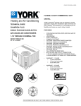
AFFINITY™ SERIES
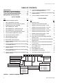
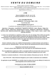
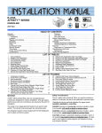
York® Affinity™ Series packaged cooling/heating air conditioners are designed for outdoor installation. Only utility and
duct connections are required at the point of installation.
SINGLE PACKAGE GAS/ELECTRIC
The gas-fired heaters have aluminized steel tubular heat
exchangers and hot surface to pilot ignition. They are available in natural gas with field conversion to propane.
AIR COOLED AIR CONDITIONERS
FEATURING
2 THRU 5 NOMINAL TON
•
•
DNP024, 030, 036, 042, 048 AND 060
13 SEER
•
•
•
•
•
•
•
•
•
•
•
FACTORY MOUNTED TXV
COOLING/GAS HEATING UNITS (NATURAL GAS OR
PROPANE)
LOW PROFILE
QUIET OPERATION
COMMON FOOTPRINT
OPTIONAL SLIDE IN MOTORIZED DAMPERS
OPTIONAL SLIDE IN ECONOMIZERS
OPTIONAL PROPANE CONVERSION KIT
OPTIONAL HIGH ALTITUDE CONVERSION KIT
(NATURAL GAS/PROPANE)
OPTIONAL LOW NOx KIT
FULL PERIMETER BASE RAILS
BOTTOM AND SIDE UTILITY CONNECTIONS
1” OR 2” CLEANABLE FILTERS STANDARD ON ALL
3 PHASE MODELS. OPTIONAL ON 1 PHASE MODELS
•
WARRANTY - 1 PHASE
•
10 year compressor
•
20 year heat exchanger
•
5 year other parts
•
WARRANTY - 3 PHASE
•
5 year compressor
•
10 year heat exchanger
•
1 year other parts
FOR DISTRIBUTION USE ONLY - NOT TO BE USED AT POINT OF RETAIL SALE
036-21366-007-A-1205
TABLE OF CONTENTS
DESCRIPTION . . . . . . . . . . . . . . . . . . . . . . . . . . . . . 1
STANDARD FEATURES/BENEFITS . . . . . . . . . . . . 3
FIELD-INSTALLED ACCESSORIES . . . . . . . . . . . . 4
TYPICAL WIRING DIAGRAM NOTES . . . . . . . . . . 32
MECHANICAL SPECIFICATIONS . . . . . . . . . . . . . 33
19
TYPICAL WIRING DIAGRAM D*NP 030-048
(460/575-3-60 POWER SUPPLY) . . . . . . . . . . . . . . . 30
20
TYPICAL WIRING DIAGRAM D*NP 060 (460/575-3-60
POWER SUPPLY) . . . . . . . . . . . . . . . . . . . . . . . . . . . 31
21
TYPICAL WIRING DIAGRAM LEGEND . . . . . . . . . . 32
LIST OF FIGURES
Fig#
LIST OF TABLES
Pg#
1
PRODUCT NOMENCLATURE . . . . . . . . . . . . . . . . . . 2
Tbl#
2
UNIT COMPONENT LOCATION . . . . . . . . . . . . . . . . . 6
1
PHYSICAL DATA . . . . . . . . . . . . . . . . . . . . . . . . . . . . . 6
3
FIELD WIRING DIAGRAM CONTROL WIRING . . . . 18
2
RATINGS COOLING/GAS HEATING . . . . . . . . . . . . . 7
4
POWER WIRING FIELD DIAGRAM . . . . . . . . . . . . . 19
3
DNP024 COOLING CAPACITIES - 2 TON . . . . . . . . . 8
5
UNIT DIMENSIONS - FRONT . . . . . . . . . . . . . . . . . . 20
4
DNP030 COOLING CAPACITIES - 2-1/2 TON . . . . . 10
6
UNIT DIMENSIONS - FRONT & BOTTOM . . . . . . . . 21
5
DNP036 COOLING CAPACITIES - 3 TON . . . . . . . . 11
7
UNIT DIMENSIONS - BACK & BOTTOM . . . . . . . . . 21
6
DNP042 COOLING CAPACITIES - 3-1/2 TON . . . . . 12
8
TYPICAL SLAB ON GROUND INSTALLATION . . . . 22
7
DNP048 COOLING CAPACITIES - 4 TON . . . . . . . . 13
9
TYPICAL ROOF CURB INSTALLATION . . . . . . . . . . 22
8
DNP060 COOLING CAPACITIES - 5 TON . . . . . . . . 14
10
TYPICAL DUCT APPLICATIONS . . . . . . . . . . . . . . . 23
9
TWO TON AIR PERFORMANCE . . . . . . . . . . . . . . . 15
11
UNIT CENTER OF GRAVITY . . . . . . . . . . . . . . . . . . 23
12
ROOF CURB DIMENSIONS . . . . . . . . . . . . . . . . . . . 24
10 SIDE SUPPLY AIR BLOWER PERFORMANCE 208/230 VOLTS . . . . . . . . . . . . . . . . . . . . . . . . . . . . . 16
13
ROOF CURB CROSS SECTION . . . . . . . . . . . . . . . . 24
14
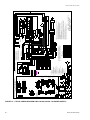
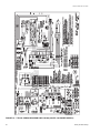
TYPICAL WIRING DIAGRAM D*NP 024 (208/230-1-60
POWER SUPPLY) . . . . . . . . . . . . . . . . . . . . . . . . . . . 25
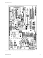
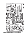
15
TYPICAL WIRING DIAGRAM D*NP 030-048 (208/2301-60 POWER SUPPLY) . . . . . . . . . . . . . . . . . . . . . . . 26
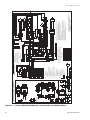
16
TYPICAL WIRING DIAGRAM D*NP 060 (208/230-1-60
POWER SUPPLY) . . . . . . . . . . . . . . . . . . . . . . . . . . . 27
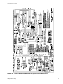
17
TYPICAL WIRING DIAGRAM D*NP 030-048 (208/2303-60 POWER SUPPLY) . . . . . . . . . . . . . . . . . . . . . . . 28
15 UNIT DIMENSIONS FRONT . . . . . . . . . . . . . . . . . . . 20
TYPICAL WIRING DIAGRAM D*NP 060 (208/230-3-60
POWER SUPPLY) . . . . . . . . . . . . . . . . . . . . . . . . . . . 29
17 UNIT WEIGHTS AND CENTER OF GRAVITY . . . . . 23
18
'
1
Pg#
11 BOTTOM SUPPLY AIR BLOWER PERFORMANCE 208/230 VOLTS . . . . . . . . . . . . . . . . . . . . . . . . . . . . . 17
12 ADDITIONAL STATIC PRESSURE RESISTANCE 2, 2-1/2, 3 TON . . . . . . . . . . . . . . . . . . . . . . . . . . . . . . 18
13 ADDITIONAL STATIC PRESSURE RESISTANCE 3-1/2, 4 AND 5 TON . . . . . . . . . . . . . . . . . . . . . . . . . . 18
14 ELECTRICAL DATA . . . . . . . . . . . . . . . . . . . . . . . . . . 19
16 UNIT MINIMUM CLEARANCES . . . . . . . . . . . . . . . . 20
3
1
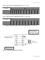
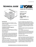
352'8&7&$7(*25<
92/7$*( &2'(
' 6LQJOH3DFNDJH$LU&RQGLWLRQHU
352'8&7*(1(5$7,21
VW*HQHUDWLRQ
QG*HQHUDWLRQ
120,1$/*$6+($7,1*
287387&$3$&,7<
352'8&7,'(17,),(5
13 6((5*DV+HDW(OHFWULF
120,1$/&22/,1*
&$3$&,7<0%+
%78+
%78+
%78+
%78+
%78+
%78+
)$&725<
,167$//('*$6+($7
1 1DWXUDO*DV+HDW,QVWDOOHG
%78+
%78+
%78+
%78+
%78+
%78+
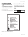
FIGURE 1 - PRODUCT NOMENCLATURE
2
Unitary Products Group
036-21366-007-A-1205
STANDARD FEATURES/BENEFITS
OPERATING EFFICIENCY - All units provide high operating
efficiencies and have a minimum AFUE of 80% and SEER of
13.0. All efficiencies exceed legislated minimum levels.
ON SITE FLEXIBILITY - All model sizes share a common,
compact design cabinet in a single footprint. The installer has
the flexibility of setting one curb and placing the proper tonnage unit on that curb after the internal load has been determined. Field convertible duct connections from side shot to
down shot allows the installer to have greater flexibility with
less inventory.
LOWER INSTALLATION COST - Installation time and costs
are reduced by easy power and control wiring connections.
The small base dimension means less space is required on
the ground or roof, plus, the installer can fit this unit between
the wheel wells of full size pick-up truck. All models are well
under 500 pounds.
All units are completely wired, charged with R-22 and tested
prior to shipment. Unique test stations using a new state of the
art computerized process system are used to insure product
quality. Refrigerant charge and component part numbers are
verified via computers at assembly. Vital run test statistics
such as system pressure, motor currents, air velocity and temperature, unit vibration, and gas system safeties are monitored
and recorded by the system to insure unit performance.
Equal size, side supply and return duct connections allows
easy hook-up of ducts to match low crawl spaces without
transition pieces.
UTILITY CONNECTIONS MADE EASY - Gas and electric
utility knockouts are provided through the bottom as well as
the side of the unit. Utility connections can be made quickly
and with a minimum amount of field labor. A field supplied
and field installed electrical disconnect switch must be
installed.
CONVERTIBLE AIRFLOW DESIGN - The bottom duct openings are covered when they leave the factory ready to be
used for a side supply / side return application. If a bottom
supply / bottom return application is desired, you simply
remove the two panels from the bottom of the unit and place
them in the side supply / side return duct openings. No panel
cutting is required and no accessory panel is necessary.
Convertible airflow design allows maximum field flexibility and
minimum inventory.
CONDENSATE PAN - A non-corrosive, long-lasting, watertight pan is positioned below the evaporator coil to collect and
drain all condensate. Less collection of stagnate condensate
Unitary Products Group
will build-up. The condensate pan conforms to ASHRAE 6289 standards (Ventilation for Acceptable Indoor Air Quality).
CONDENSATE DRAIN - The heavy duty, 3/4 inch NPTI copper connection is more durable over time. The connection is
rigidly mounted to assure proper fit and leak tight seal.
DURABLE FINISH - With a heavy duty cabinet made of powder-painted, galvanized steel the neutral color blends into
surrounding areas. The powdered paint provides a better
paint to steel bond, which resists corrosion and rust creep.
The special primer formulas and glossy finish insures less
fading when exposed to sunlight and offers a more attractive
on site appearance. This paint finish meets ASTM-B117 standards for 1000 hours salt spray rating. The highest in the
industry.
FULL PERIMETER BASE RAILS - The easily removable
base rails provide a solid foundation for the entire unit and
protects the unit during shipment. The rails provide fork lift
access from all sides, and rigging holes are also provided so
that an overhead crane can be used to place the units on a
roof. On applications where the unit is placed on a pad, the
base will keep the unit off the pad to deter corrosion. On
applications where height is limited, the inch high base rails
may be removed on location.
MORE ATTRACTIVE APPEARANCE - A single piece Water
Shed top cover containing a top discharge condenser fan
arrangement requires less square footage on installation and
provides a wider variety of installations. The one piece design
adds greater water integrity. Rounded corners with water drip
edges add to the attractive appearance. The cabinet panels
have a non-fibrous insulation that will not release insulation
fibers into conditioned area.
TOP DISCHARGE - The top discharge condenser fan does
not disrupt neighboring areas or dry-out vegetation surrounding the unit. The warm air from the top mounted fan is blown
up away from the structure and any landscaping. This allows
compact location on multi-unit applications.
CONDENSER COIL GRILLE - A multi-piece totally enclosed,
rigidly mounted condenser coil grille provides protection from
objects after installation and provides protection during transit.
LOW OPERATING SOUND LEVEL - The upward air flow
carries the normal operating noise up and away from the living area. The rigid top panel effectively isolates any motor
sound. Isolator mounted compressor and the rippled fins of
the condenser coil muffle the normal fan motor and compressor operating sounds. The unique formed base pan also aids
in sound alterations with it's Super-Structure design. This
design strategically places embossments in the pan for optimum strength and rigidity.
3
036-21366-007-A-1205
FAN SYSTEM - All 2-1/2, 3, 3-1/2 and 4 ton models operate
over a wide range of design conditions with a constant CFM,
electrically commutated (ECM) fan motor. These units easily
match all types of applications and provide greater on site
flexibility to match comfort requirement. These models have 2
cooling speeds and a single heating speed. The cooling
speed is factory set and can be field adjusted to a second
speed. The heating speed is factory set to maintain mid point
rise at the units heating input. It cannot be field adjusted. This
allows maximum comfort conditions.
LOW MAINTENANCE - Long life, permanently lubricated
condenser and evaporator fan motor bearings need no
annual maintenance adding greater reliability to the unit.
Blower assembly can be easily cleaned by the unique SlipTrack slide-out blower assembly.
Two ton models operate over a wide range of design conditions with a 3-speed direct-drive fan motor. These single
phase models have the Comfort-Match system that allows
different speed taps for heating or cooling operations.
EASY SERVICE ACCESS - A large, single panel covers the
electrical and gas controls makes servicing easy. The blower
compartment has an additional large panel with a built-in
handle tab. Removing this panel will allow the blower assembly to slide-out for easy removal for maintenance and ease of
trouble shooting.
SIMPLE CONTROL CIRCUIT - A low voltage printed circuit
board contains a diagnostic indicator light and a low voltage
terminal strip. An additional set of pin connectors is also provided to simplify the field interface of external controls. Maten-lock plug connectors are used. The electrical control box is
not located in the compressor compartment. The controls are
mounted on a Control-Tilt control panel to allow the access
cover to be removed for trouble shooting and maintenance
without affecting the normal system operating pressures. All
wiring internal to the unit is color/number coded.
PROTECTED COMPRESSOR - The compressor is internally
protected against high pressure and temperature. This is
accomplished by the simultaneous operation of high pressure
relief valve and a temperature sensor which protect the compressor if undesirable operating conditions occur.
EXCLUSIVE COIL DESIGN - Grooved copper tubes and
enhanced aluminum fin construction improves heat transfer
for maximum efficiency and durability.
HEAT EXCHANGERS - Are corrosion-resistant, aluminizedsteel tubular construction to provide long-life, trouble-free
operation. The unique blow-through design also assures that
condensate does not collect in humid areas when in the cooling cycle. This adds to longer heat exchanger life and higher
long term efficiencies.
POST PURGE INDUCED DRAFT COMBUSTION - Exhausts
combustion products from the heat exchanger upon completion of the heating cycle to prolong the heat exchanger life.
SELF DIAGNOSTIC FAN CONTROL MODULE - Due to this
self diagnostic control, less on site time is required to trouble
shoot these units.
HOT SURFACE TO PILOT IGNITION - Provides faster heat
delivery. This ignition is highly reliable, durable and eliminates nuisance lockouts. Also assures starts in damp conditions.
MULTI PORT IN-SHOT BURNERS - No field adjustment is
required to mix the air and gas. These burners are constructed of high-grade corrosion-resistant, aluminized-steel.
4
SECURED SERVICE ACCESS PORTS - Protected, externally mounted, re-usable service access ports are provided
on both the high and low lines for ease of evacuating and
charging the system. No final field mounting required.
REPLACEMENT PARTS - The installer requires no special
training to replace any of the components of these units and
does not need to maintain an inventory of unique parts.
SYSTEM INTEGRATION - Each unit has the internal ability
to integrate an electronic air cleaner or humidifier to work in
conjunction with the base unit.
FIELD-INSTALLED ACCESSORIES
LOW NOx KIT - Kit includes all the necessary hardware and
instructions to field convert units to reduce emissions to less
than 40 nanogram per Joule. California requirement on single
phase models only.
PROPANE CONVERSION KIT - Kit includes burner orifices,
gas valve conversion and installation instructions necessary
to field convert unit from natural gas to propane.
HIGH ALTITUDE CONVERSION KIT (Natural Gas/Propane)
- Kit includes all necessary labels and instructions to field
alter units with natural gas/propane for installations above
2000 feet. Burner orifices must be obtained from Source 1
Parts. Propane Conversion Kit must be obtained separately.
ECONOMIZER DOWN DISCHARGE / SUPPLY KIT - Modulating integrated economizer provides simultaneous operation between the mechanical cooling and economizer
operation. Independent blade design insures proper control
and less than 1% leak rate. Includes hood and mesh bird
screen filter integrated into the hood, dry bulb sensor and
relief damper. Separate field accessories of single enthalpy
and dual enthalpy are also available. A built-in barometric
relief of 25% is provided.
SINGLE ENTHALPY SENSOR - Sensor replaces dry bulb
sensor standard in economizer kit. Provides improved economizer operation by sensing the dry bulb temperature from
outdoors plus the enthalpy content of the outdoor air.
DUAL ENTHALPY SENSOR - Additional sensor to single
enthalpy sensor. Sensor senses both the return air temperature dry bulb and humidity in conjunction with the single
Unitary Products Group
036-21366-007-A-1205
enthalpy to determine the most economical mix. Single
Enthalpy sensor also required.
50% of outdoor air (field supplied). Closes on power loss,
includes hood and screen assembly.
PRESSURE SWITCH UPGRADE KIT - Contains screw in
type High pressure, Low Pressure/Loss of Charge switch,
freeze protection switch and lockout relay. Switches are
placed onto existing scharder ports located in the unit by furnished adapters. When abnormal conditions are sensed
through the pressure switches, the unit will lock out preventing any further operation until reset or problem is corrected.
Package agency approved.
RECTANGLE TO ROUND ADAPTERS - Kit includes one
supply and one return air rectangle to round duct adapter.
Adapters are preformed and designed to fit over current duct
openings on the base unit. Transition is from side square duct
opening to 14" round duct opening.
HAIL GUARD KIT - Kit contains protective grilles made of
expanded aluminum with full perimeter frame. Sloped hoods
are also included to assure maximum protection.
ANTI SHORT CYCLE TIMER - Automatically prevents the
compressor from restarting for 5 minutes after cycled off.Not
required if Thermostat 2ET07700224 and 2ET04700224 are
used.
FILTER / FRAME KIT (Single Phase only) - Kit contains the
necessary hardware to field install return air filters into the
base unit. Pre-cut filter racks and appropriate cleanable standard size filters are shipped in one kit. The filter rack is suitable for either 1" or 2" filters. (1" filter is supplied) This kit is
available for single phase horizontal or vertical duct application only. Standard in all 3 Phase models.
MOTORIZED FRESH AIR DAMPER - Designed for duct
mounted side supply/return and unit mounted down supply/
return applications. Damper capable of providing 0% through
Unitary Products Group
ROOF CURBS - NRCA approved curbs provide proper fit to
base unit for rooftop installations. Curbs are designed to be
assembled through hinge pins in each corner. Kit also provides seal strip to assure a water tight seal. 8 and 14 inch
high roof curbs are available.
MANUAL OUTDOOR DAMPER - Provides 0% through 50%
outdoor air capability (field adjustable). Designed for duct
mounted side supply/return applications. Includes hood and
screen assembly.
WALL THERMOSTAT - The units are designed to operate
with 24-volt electronic and electro-mechanical thermostats.
All units can operate with single stage heat / single stage cool
thermostats - with or without the economizer.
LOW AMBIENT KIT - Kit provides necessary hardware to
convert unit to operate in cooling cycle down to 0º F. Standard unit operation 45º F.
TRANSFORMER KIT - Kit provides necessary hardware to
provide single phase models from factory furnished 40 VA
transformer capability to 75 VA transformer capability.
(Required on installations with economizer or motorized
damper.)
5
036-21366-007-A-1205
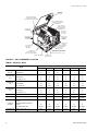
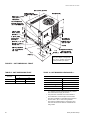
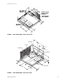
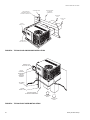
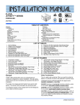
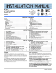
DIRECT DRIVE
CONDENSER
FAN MOTOR
BLOW-THROUGH DESIGN
WITH RELIABLE ALUMINIZED
STEEL TUBULAR HEAT EXC HANGERS
HIGHLY EFFICIENT E NHANCE D
COPPER TUBE/ALUMINUM FIN
EVAPORATOR COIL
HIGHLY EFFICIENT
ENHANCED COPPER
TUBE/ALUMINUM FIN
CONDENSER COIL
LONG LASTING
POWDER PAINT
FINISH
DECORATIVE
PROTECTIVE
COIL GAURD
REAR AND BOTTOM
RETU RN AIR
AND SUPPLY AIR
DUCT OPENINGS
HIGH EFFICIENCY
COMPRESSOR
RIGIDLY
MOUNTED
HOT SURFACE PILOT
ASSEMBLY
HIGH GRADE ALUMINIZED
IN-SHOT BURNERS
HEAVY GAUGE
REMOVABLE
BASE RAILS
LOW VOLTAGE
TERMINAL BLOCK
SELF-DIAGNOSTIC CONTROLS WITH
"COMFORT-MATCH" SPEED CONTROL
DIRECT DRIVE
BLOWER MOTOR WITH
SLIDE-OUT BLOWER ASSEMBLY
AUTOMATIC GAS VALVE (1/2" - 14 NPTI)
POWER VENTER MOTOR
HIGH VOLTAGE
TERMINAL BLOCK
FIGURE 2 - UNIT COMPONENT LOCATION
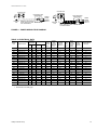
TABLE 1: PHYSICAL DATA
DNP
MODEL
EVAPORATOR CENTRIFUGAL BLOWER (Dia. x W. in.)
BLOWER
FAN MOTOR HP
ROWS DEEP
EVAPORATOR
FINS PER INCH
COIL
FACE AREA (Sq. Ft.)
CONDENSER
FAN
CHARGE
FILTER
FURNACE
SECTION
036
042
048
060
10 x 8
10 x 8
11 x 10
12 x 11
12 x 11
12 x 11
1/2
3/4
3/4
1
1
1
2
3
3
3
3
3
15
13
13
13
16
16
4.5
3.5
3.5
3.5
4.5
4.5
22
22
22
22
22
22
FAN MOTOR HP
1/4
1/4
1/4
1/4
1/3
1/3
2,200
2,400
2,400
2,400
3,000
3,500
ROWS DEEP
2
1
2
2
2
2
FINS PER INCH
20
20
20
20
20
20
FACE AREA (Sq. Ft.)
11.7
11.7
11.7
14.7
14.7
14.7
REFRIGERANT 22 (lbs./oz.)
6/4
4/9
6 / 12
9/6
8/4
8/8
2.6 / 19 x 19.5
2.6 / 19 x 19.5
2.6 / 19 x 19.5
NATURAL GAS BURNER ORIFICE NO.
(Drill Size)
43
43
43
40
40
40
PROPANE BURNER ORIFICE NO.
(Drill Size)
55
55
55
53
53
53
1/2 NPTI
1/2 NPTI
1/2 NPTI
1/2 NPTI
1/2 NPTI
1/2 NPTI
Recip
Scroll
Scroll
Scroll
Scroll
Scroll
FACE AREA (Sq. Ft.) Size (Actual)
GAS CONNECTION SIZE
COMPRESSOR HERMETIC TYPE, (Qty. = 1)
6
030
PROPELLER DIA. (in.)
NOM. CFM TOTAL
CONDENSER
COIL
024
3.1 / 19.5 x 11.5 3.1 / 19.5 x 11.5 3.1 / 19.5 x11.5
(2 Reqd.)
(2 Reqd.)
(2 Reqd.)
Unitary Products Group
036-21366-007-A-1205
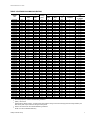
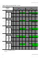
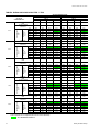
TABLE 2: RATINGS COOLING/GAS HEATING
NET COOLING CAPACITY1
MODEL
DNP
MBH
SEER3
024N03606
024N05606
030N03606
030N03625
030N03646
030N05606
030N05625
030N05646
036N03606
036N03625
036N03646
036N03658
036N05606
036N05625
036N05646
036N05658
036N07206
036N07225
036N07246
036N07258
042N06506
042N06525
042N06546
042N06558
042N09006
042N09025
042N09046
042N09058
048N06506
048N06525
048N06546
048N06558
048N09006
048N09025
048N09046
048N09058
048N11006
048N11025
048N11046
048N11058
060N06506
060N06525
060N06546
060N06558
060N09006
060N09025
060N09046
060N09058
060N11006
060N11025
060N11046
060N11058
25.4
25.4
30.6
30.6
30.6
30.6
30.6
30.6
37.4
37.4
37.4
37.4
37.4
37.4
37.4
37.4
37.4
37.4
37.4
37.4
44
44
44
44
44
44
44
44
48
48
48
48
48
48
48
48
48
48
48
48
55.5
55.5
55.5
55.5
55.5
55.5
55.5
55.5
55.5
55.5
55.5
55.5
13.3
13.3
13.4
13.4
13.4
13.4
13.4
13.4
13.65
13.65
13.65
13.65
13.65
13.65
13.65
13.65
13.65
13.65
13.65
13.65
13.7
13.7
13.7
13.7
13.7
13.7
13.7
13.7
13.2
13.2
13.2
13.2
13.2
13.2
13.2
13.2
13.2
13.2
13.2
13.2
13.0
13.0
13.0
13.0
13.0
13.0
13.0
13.0
13.0
13.0
13.0
13.0
GAS HEAT CAPACITY / EFFICIENCIES
EER4
SOUND
RATING
(dbels)2
INPUT
(MBH)
OUTPUT
(MBH)
AFUE5
(%)
NUMBER OF
BURNERS
11.6
11.6
11.75
11.75
11.75
11.75
11.75
11.75
11.75
11.75
11.75
11.75
11.75
11.75
11.75
11.75
11.75
11.75
11.75
11.75
10.65
10.65
10.65
10.65
10.65
10.65
10.65
10.65
11.7
11.7
11.7
11.7
11.7
11.7
11.7
11.7
11.7
11.7
11.7
11.7
11.2
11.2
11.2
11.2
11.2
11.2
11.2
11.2
11.2
11.2
11.2
11.2
81
81
80
80
80
80
80
80
81
81
81
81
81
81
81
81
81
81
81
81
80
80
80
80
80
80
80
80
84
84
84
84
84
84
84
84
84
84
84
84
84
84
84
84
84
84
84
84
84
84
84
84
45
70
45
45
45
70
70
70
45
45
45
45
70
70
70
70
90
90
90
90
80
80
80
80
108
108
108
108
80
80
80
80
108
108
108
108
135
135
135
135
80
80
80
80
108
108
108
108
135
135
135
135
36
56
36
36
36
56
56
56
36
36
36
36
56
56
56
56
72
72
72
72
64
64
64
64
86
86
86
86
64
64
64
64
86
86
86
86
107
107
107
107
64
64
64
64
86
86
86
86
107
107
107
107
80.2
80.2
80.2
80.2
80.2
80.2
80.2
80.2
80.4
80.4
80.4
80.4
80.2
80.2
80.2
80.2
80.1
80.1
80.1
80.1
80.6
80.6
80.6
80.6
80.8
80.8
80.8
80.8
80.8
80.8
80.8
80.8
80.6
80.6
80.6
80.6
80.5
80.5
80.5
80.5
80.8
80.8
80.8
80.8
80.6
80.6
80.6
80.6
80.5
80.5
80.5
80.5
2
3
2
2
2
3
3
3
2
2
2
2
3
3
3
3
4
4
4
4
3
3
3
3
4
4
4
4
3
3
3
3
4
4
4
4
5
5
5
5
3
3
3
3
4
4
4
4
5
5
5
5
TEMP.
RISE
(°F) RANGE
25 - 55
30 - 60
25 - 55
25 - 55
25 - 55
30 - 60
30 - 60
30 - 60
25 - 55
25 - 55
25 - 55
25 - 55
25 - 55
25 - 55
25 - 55
25 - 55
30 - 60
30 - 60
30 - 60
30 - 60
25 - 55
25 - 55
25 - 55
25 - 55
45 - 75
45 - 75
45 - 75
45 - 75
25 - 55
25 - 55
25 - 55
25 - 55
35 - 65
35 - 65
35 - 65
35 - 65
45 - 75
45 - 75
45 - 75
45 - 75
25 - 55
25 - 55
25 - 55
25 - 55
35 - 65
35 - 65
35 - 65
35 - 65
45 - 75
45 - 75
45 - 75
45 - 75
1.
Net Cooling Capacity = ARI 210 standard rating conditions.
2.
(dbels) = ARI 270-95
3.
Seasonal Energy Efficiency Ratio - the total cooling output in BTU’s during a normal annual usage period for cooling divided by the
total electric power input in watt-hours during the same period.
4.
Tested in accordance with ARI 210 Standard Rating Conditions.
5.
AFUE = Annual Fuel Utilization Efficiency.
Unitary Products Group
7
036-21366-007-A-1205
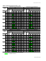
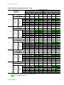
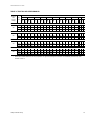
TABLE 3: DNP024 COOLING CAPACITIES - 2 TON
AIR ON
EVAPORATOR
COIL
CFM
600
700
800
900
1000
600
700
800
900
1000
1.
TEMPERATURE OF AIR ON CONDENSER COIL
85°F
95°F
SENSIBLE CAPACITY1
NET
CAP.
MBH
POWER
INPUT
KW
72
24.7
1.90
15.0
13.3
11.6
67
22.6
1.91
18.4
16.7
14.9
62
20.9
1.89
20.9
19.5
17.8
57
20.6
1.88
20.6
20.2
72
26.4
1.94
17.0
14.9
67
24.1
1.94
20.7
18.7
62
22.3
1.93
22.3
21.6
57
22.0
1.92
22.0
21.8
72
28.0
1.97
19.0
16.6
WB
°F
ENTERING DRY BULB, °F
86
83
80
77
NET
CAP.
MBH
POWER
INPUT
KW
SENSIBLE CAPACITY1
ENTERING DRY BULB, °F
74
71
68
86
83
80
9.9
8.1
#N/A
#N/A
23.1
2.03
15.0
13.3
11.6
13.2
11.5
9.8
8.1
21.0
2.03
18.1
16.4
14.7
16.1
14.4
12.7
11.0
19.5
2.00
19.5
19.4
17.7
18.5
16.8
15.1
13.4
11.7
19.5
1.99
19.5
19.5
12.9
10.9
8.9
#N/A
#N/A
24.6
2.08
16.7
14.7
16.7
14.7
12.7
10.6
8.6
22.3
2.08
20.1
18.1
19.9
17.9
15.9
13.9
11.8
20.7
2.05
20.7
20.7
20.7
18.7
16.7
14.6
12.6
20.7
2.04
20.7
14.3
12.0
9.6
#N/A
#N/A
26.0
2.13
18.5
77
74
71
68
9.9
8.1
#N/A
#N/A
13.0
11.3
9.5
7.8
16.0
14.3
12.5
10.8
17.9
16.2
14.5
12.7
11.0
12.7
10.7
8.6
#N/A
#N/A
16.1
14.1
12.1
10.0
8.0
19.4
17.4
15.3
13.3
11.3
20.7
19.6
17.6
15.6
13.5
11.5
16.1
13.8
11.5
9.1
#N/A
#N/A
67
25.6
1.98
23.1
20.8
18.5
16.1
13.8
11.5
9.1
23.7
2.13
22.2
19.8
17.5
15.2
12.8
10.5
8.2
62
23.7
1.96
23.7
23.7
22.0
19.7
17.4
15.0
12.7
22.0
2.09
22.0
22.0
21.1
18.8
16.4
14.1
11.8
57
23.3
1.95
23.3
23.3
22.9
20.5
18.2
15.9
13.5
22.0
2.09
22.0
22.0
21.3
19.0
16.7
14.3
12.0
72
28.2
2.01
20.4
17.7
15.1
12.4
9.8
#N/A
#N/A
26.2
2.15
19.9
17.2
14.6
11.9
9.3
#N/A
#N/A
67
25.8
2.01
24.5
22.1
19.5
16.8
14.2
11.5
8.8
23.9
2.15
23.1
21.2
18.5
15.8
13.2
10.5
7.9
62
23.8
1.99
23.8
23.8
23.0
20.3
17.7
15.0
12.4
22.1
2.12
22.1
22.1
21.7
19.1
16.4
13.7
11.1
57
23.5
1.98
23.5
23.5
23.2
20.6
17.9
15.3
12.6
22.2
2.11
22.2
22.2
21.8
19.2
16.5
13.9
11.2
72
28.3
2.04
21.8
18.8
15.9
12.9
9.9
#N/A
#N/A
26.5
2.18
21.3
18.3
15.4
12.4
9.4
#N/A
#N/A
67
25.9
2.04
25.9
23.5
20.5
17.5
14.5
11.5
8.6
24.1
2.18
24.1
22.5
19.5
16.5
13.5
10.5
7.6
62
24.0
2.02
24.0
24.0
24.0
21.0
18.0
15.0
12.0
22.3
2.14
22.3
22.3
22.3
19.3
16.4
13.4
10.4
57
23.6
2.01
23.6
23.6
23.6
20.6
17.6
14.7
11.7
22.3
2.14
22.3
22.3
22.3
19.4
16.4
13.4
10.4
AIR ON
EVAPORATOR
COIL
CFM
TEMPERATURE OF AIR ON CONDENSER COIL
TEMPERATURE OF AIR ON CONDENSER COIL
TEMPERATURE OF AIR ON CONDENSER COIL
105°F
115°F
NET
CAP.
MBH
POWER
INPUT
KW
72
21.5
67
19.5
62
WB
°F
SENSIBLE CAPACITY1
ENTERING DRY BULB, °F
86
83
80
2.20
14.4
12.7
10.9
2.17
17.6
15.9
14.2
18.4
2.15
18.4
18.3
16.7
57
18.5
2.15
18.5
18.5
72
22.8
2.24
16.0
14.0
77
NET
CAP.
MBH
POWER
INPUT
KW
SENSIBLE CAPACITY1
ENTERING DRY BULB, °F
74
71
68
86
83
80
9.2
7.5
#N/A
#N/A
20.0
2.36
13.7
12.0
10.3
12.5
10.8
9.1
7.4
18.1
2.30
17.2
15.4
13.7
15.0
13.3
11.6
9.9
17.3
2.30
17.3
17.3
15.7
16.9
15.2
13.5
11.8
10.0
17.5
2.31
17.5
17.5
12.0
9.9
7.9
#N/A
#N/A
21.0
2.40
15.3
13.3
77
74
71
68
8.6
6.9
#N/A
#N/A
12.0
10.3
8.6
6.9
14.0
12.3
10.6
8.9
15.9
14.2
12.5
10.8
9.1
11.2
9.2
7.2
#N/A
#N/A
67
20.7
2.21
19.4
17.6
15.5
13.5
11.5
9.5
7.4
19.0
2.34
18.6
17.0
15.0
12.9
10.9
8.9
6.9
62
19.5
2.19
19.5
19.4
18.3
16.2
14.2
12.2
10.2
18.2
2.34
18.2
18.2
17.2
15.1
13.1
11.1
9.1
57
19.6
2.19
19.6
19.6
18.5
16.4
14.4
12.4
10.4
18.4
2.35
18.4
18.4
17.3
15.3
13.3
11.3
9.2
72
24.1
2.28
17.6
15.3
13.0
10.6
8.3
#N/A
#N/A
22.1
2.43
16.8
14.5
12.2
9.8
7.5
#N/A
#N/A
67
21.8
2.25
21.1
19.2
16.9
14.5
12.2
9.9
7.5
20.0
2.38
20.0
18.5
16.2
13.9
11.5
9.2
6.9
62
20.5
2.24
20.5
20.5
19.8
17.5
15.2
12.8
10.5
19.1
2.38
19.1
19.1
18.6
16.2
13.9
11.6
9.2
57
20.7
2.24
20.7
20.7
20.0
17.7
15.4
13.0
10.7
19.3
2.38
19.3
19.3
18.7
16.4
14.1
11.7
9.4
72
24.3
2.32
19.0
16.3
13.7
11.0
8.3
#N/A
#N/A
22.3
2.48
18.1
15.4
12.7
10.1
7.4
#N/A
#N/A
67
22.0
2.29
21.6
20.3
17.7
15.1
12.4
9.8
7.1
20.2
2.43
20.2
19.5
17.0
14.3
11.6
9.0
6.3
62
20.7
2.27
20.7
20.7
20.4
17.7
15.1
12.4
9.7
19.3
2.43
19.3
19.3
19.0
16.4
13.7
11.1
8.4
57
20.8
2.27
20.8
20.8
20.5
17.9
15.2
12.6
9.9
19.5
2.43
19.5
19.5
19.2
16.6
13.9
11.3
8.6
72
24.5
2.36
20.3
17.3
14.3
11.4
8.4
#N/A
#N/A
22.5
2.53
19.3
16.3
13.3
10.3
7.4
#N/A
#N/A
67
22.2
2.33
22.2
21.4
18.6
15.6
12.6
9.7
6.7
20.4
2.47
20.4
20.4
17.7
14.8
11.8
8.8
5.8
62
20.9
2.31
20.9
20.9
20.9
17.9
15.0
12.0
9.0
19.5
2.47
19.5
19.5
19.5
16.5
13.5
10.6
7.6
57
21.0
2.31
21.0
21.0
21.0
18.0
15.1
12.1
9.1
19.7
2.48
19.7
19.7
19.7
16.7
13.7
10.8
7.8
These capacities are net capacities (the indoor fan heat is deducted).
ALL SENSIBLE CAPACITY
8
Unitary Products Group
036-21366-007-A-1205
TABLE 3: DNP024 COOLING CAPACITIES - 2 TON (CONT’D)
TEMPERATURE OF AIR ON CONDENSER COIL
AIR ON
EVAPORATOR
COIL
CFM
600
700
800
900
1000
1.
125°F
WB
°F
NET
CAP.
MBH
POWER
INPUT
KW
SENSIBLE CAPACITY1
ENTERING DRY BULB, °F
86
83
80
77
74
71
68
#N/A
72
18.4
2.5
13.1
11.4
9.7
8.0
6.3
#N/A
67
16.6
2.4
16.7
15.0
13.3
11.5
9.8
8.1
6.4
62
16.2
2.5
16.2
16.2
14.8
13.1
11.4
9.6
7.9
57
16.5
2.5
16.5
16.5
14.9
13.2
11.5
9.8
8.1
72
19.3
2.6
14.6
12.5
10.5
8.5
6.5
#N/A
#N/A
67
17.4
2.5
17.8
16.4
14.4
12.4
10.3
8.3
6.3
62
17.0
2.5
17.0
17.0
16.0
14.0
12.0
10.0
7.9
57
17.2
2.5
17.2
17.2
16.2
14.2
12.1
10.1
8.1
72
20.1
2.6
16.0
13.7
11.3
9.0
6.7
#N/A
#N/A
67
18.1
2.5
18.9
17.9
15.5
13.2
10.9
8.5
6.2
62
17.7
2.5
17.7
17.7
17.3
15.0
12.6
10.3
8.0
57
18.0
2.5
18.0
18.0
17.5
15.1
12.8
10.5
8.1
72
20.4
2.6
17.1
14.5
11.8
9.2
6.5
#N/A
#N/A
67
18.3
2.6
18.7
18.6
16.2
13.5
10.9
8.2
5.6
62
17.9
2.6
17.9
17.9
17.7
15.0
12.4
9.7
7.1
57
18.2
2.6
18.2
18.2
17.9
15.3
12.6
9.9
7.3
72
20.6
2.7
18.3
15.3
12.3
9.3
6.3
#N/A
#N/A
67
18.5
2.6
18.5
19.3
16.9
13.9
10.9
7.9
4.9
62
18.1
2.6
18.1
18.1
18.1
15.1
12.1
9.2
6.2
57
18.4
2.7
18.4
18.4
18.4
15.4
12.4
9.4
6.5
These capacities are net capacities (the indoor fan heat is deducted).
ALL SENSIBLE CAPACITY
Unitary Products Group
9
036-21366-007-A-1205
TABLE 4: DNP030 COOLING CAPACITIES - 2-1/2 TON
AIR ON EVAPORATOR COIL
TEMPERATURE
OF AIR ON
CONDENSER COIL
57
72
67
62
57
NET CAP.MBH
33.6
31.6
30.3
30.2
34.5
32.4
31.1
31.0
TOTAL POWER INPUT kW
2.4
2.4
2.3
2.3
2.6
2.6
2.5
2.5
86
23.6
29.2
30.3
30.2
27.2
32.4
31.1
31.0
83
20.7
26.3
30.3
30.2
23.5
29.7
31.1
31.0
80
17.8
23.4
28.4
29.6
19.7
25.9
31.1
31.0
77
14.9
20.5
25.5
26.7
16.0
22.2
27.3
27.3
74
12.0
17.5
22.6
23.8
12.3
18.5
23.6
23.5
71
N/A
14.6
19.7
20.8
N/A
14.8
19.9
19.8
68
N/A
11.7
16.8
17.9
N/A
11.0
16.2
16.1
32.7
30.5
28.8
28.9
33.5
31.3
29.6
29.7
Entering Dry
Bulb °F
62
Entering Dry
Bulb °F
MBH1
Sensible Capacity
TOTAL POWER INPUT kW
2.6
2.6
2.6
2.5
2.8
2.8
2.8
2.7
86
23.1
29.0
28.8
28.9
26.9
31.3
29.6
29.7
83
20.2
26.1
28.8
28.9
23.1
29.7
29.6
29.7
80
17.3
23.2
27.9
28.4
19.4
26.0
29.6
29.7
77
14.4
20.3
25.0
25.4
15.7
22.3
25.9
26.0
74
11.5
17.3
22.1
22.5
12.0
18.5
22.1
22.2
71
N/A
14.4
19.2
19.6
N/A
14.8
18.4
18.5
68
N/A
11.5
16.3
16.7
N/A
11.1
14.7
14.8
31.0
28.3
27.3
27.3
32.2
29.4
28.3
28.3
NET CAP.MBH
2.9
2.9
2.9
3.1
3.1
3.0
3.0
22.6
27.6
27.3
27.3
26.4
29.4
28.3
28.3
83
19.6
25.1
27.3
27.3
22.6
28.6
28.3
28.3
80
16.7
22.2
26.4
26.8
18.9
25.1
28.3
28.3
77
13.8
19.3
23.5
23.8
15.2
21.4
24.6
24.6
74
10.9
16.4
20.6
20.9
11.5
17.6
20.8
20.9
71
N/A
13.5
17.7
18.0
N/A
13.9
17.1
17.2
68
N/A
10.5
14.8
15.1
N/A
10.2
13.4
13.4
29.3
26.2
25.7
25.7
30.8
27.5
27.0
27.0
Entering Dry
Bulb °F
2.9
86
MBH1
TOTAL POWERINPUT kW
Sensible Capacity
105 °F
NET CAP.MBH
1.
3.2
3.4
3.4
3.3
3.3
25.7
25.7
25.8
27.5
27.0
27.0
83
19.0
24.1
25.7
25.7
22.1
27.5
27.0
27.0
80
16.1
21.2
24.9
25.2
18.4
24.2
27.0
27.0
77
13.2
18.3
22.0
22.2
14.7
20.5
23.3
23.2
74
10.3
15.4
19.1
19.3
10.9
16.8
19.5
19.5
71
N/A
12.5
16.2
16.4
N/A
13.0
15.8
15.8
68
N/A
9.6
13.3
13.5
N/A
9.3
12.1
12.1
NET CAP. MBH
27.6
24.1
24.2
24.0
29.4
25.6
25.7
25.6
TOTAL POWER INPUT kW
3.5
3.6
3.5
3.5
3.6
3.7
3.6
3.6
86
21.4
24.8
24.2
24.0
25.3
25.6
25.7
25.6
83
18.4
23.2
24.2
24.0
21.6
26.4
25.7
25.6
80
15.5
20.2
23.4
23.6
17.9
23.3
25.7
25.6
77
12.6
17.3
20.5
20.7
14.2
19.6
22.0
21.9
74
9.7
14.4
17.6
17.7
10.4
15.9
18.3
18.1
71
N/A
11.5
14.7
14.8
N/A
12.1
14.5
14.4
68
N/A
8.6
11.8
11.9
N/A
8.4
10.8
10.7
Entering Dry
Bulb °F
Entering Dry
Bulb °F
3.2
26.2
MBH1
3.3
22.0
Sensible Capacity
3.2
86
MBH1
125 °F
TOTAL POWER NPUT kW
Sensible Capacity
115 °F
WB °F
67
NET CAP. MBH
95 °F
1,250 CFM
WB °F
72
Sensible Capacity
MBH1
85 °F
1,000 CFM
These capacities are net capacities (the indoor fan heat is deducted)
ALL SENSIBLE CAPACITY
10
Unitary Products Group
036-21366-007-A-1205
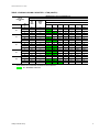
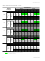
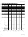
TABLE 5: DNP036 COOLING CAPACITIES - 3 TON
AIR ON EVAPORATOR COIL
TEMPERATURE
OF AIR ON
CONDENSER COIL
72
Entering Dry
Bulb °F
85 °F
Sensible Capacity
MBH1
NET CAP.
MBH
TOTAL POWER
INPUT kW
86
83
80
77
74
71
68
Entering Dry
Bulb °F
MBH1
95 °F
Sensible Capacity
NET CAP.
MBH
TOTAL POWER
INPUT kW
86
83
80
77
74
71
68
Entering Dry
Bulb °F
MBH1
105 °F
Sensible Capacity
NET CAP.
MBH
TOTAL POWER
INPUT kW
86
83
80
77
74
71
68
Entering Dry
Bulb °F
MBH1
115 °F
Sensible Capacity
NET CAP.
MBH
TOTAL POWER
INPUT kW
86
83
80
77
74
71
68
1.
Entering Dry
Bulb °F
MBH1
125 °F
Sensible Capacity
NET CAP.
MBH
TOTAL POWER
INPUT kW
86
83
80
77
74
71
68
1,200 CFM
WB °F
67
62
57
72
1,350 CFM
WB °F
67
62
57
43.3
39.9
37.4
36.7
44
40.5
38
37.2
2.93
2.89
2.9
2.88
3.08
3.05
3.06
3.04
29.5
26
22.5
19
15.5
-
35.8
32.3
28.8
25.3
21.8
18.3
14.8
37.4
37.4
36.7
36.7
31.8
27.8
38.4
34.4
38
38
37.2
37.2
34.8
31.3
27.8
24.3
20.8
35.6
32.1
28.6
25.1
21.6
23.8
19.9
15.9
-
30.4
26.4
22.5
18.5
14.5
36.7
32.7
28.7
24.7
20.7
36.7
32.7
28.7
24.7
20.7
41.4
37.1
35.7
35.3
42.5
38
36.6
36.2
3.22
3.27
3.18
3.15
3.32
3.37
3.28
3.25
28.5
25
21.5
18
14.5
-
34.8
31.3
27.8
24.3
20.8
17.3
13.8
35.7
35.7
33.5
30
26.5
23
19.5
35.3
35.3
33.9
30.4
26.9
23.4
19.9
31
27
23
19
15
-
36.9
33.7
29.7
25.7
21.7
17.7
13.8
36.6
36.6
25.5
31.5
17.6
23.6
19.6
36.2
36.2
35.5
31.5
27.5
23.5
19.5
38.5
34.8
33.9
33.6
39.6
35.8
34.8
34.5
3.61
3.61
3.5
3.48
3.73
3.72
3.61
3.59
27.6
24.1
20.6
17.1
13.6
-
33.6
30.1
26.6
23.1
19.6
16.1
12.6
33.9
33.9
32
28.5
25
21.5
18
33.6
33.6
32.2
28.7
25.2
21.7
18.2
29.9
26
22
18
14
-
35.1
32.4
28.4
24.4
20.5
16.5
12.5
34.8
34.8
33.9
29.9
25.9
21.9
18
34. 5
34.5
33.8
29.8
25.8
21.8
17.9
35.6
32.6
32.2
31.9
36.7
33.5
33.1
32.8
4.01
3.95
3.82
3.8
4.14
4.07
3.93
3.92
26.6
23.1
19.6
16.1
12.6
-
32.4
28.9
25.4
21.9
18.4
14.9
11.4
32.2
32.2
30.6
27.1
23.6
20.1
16.6
31.9
31.9
30.6
27.1
23.6
20.1
16.6
28.9
24.9
21
17
13
-
33.4
31.1
27.1
23.2
19.2
15.2
11.2
33.1
33.1
32.3
28.3
24.3
20.3
16.3
32.8
32.8
32.1
28.1
24.1
20.2
16.2
32.8
30.2
30.4
30.1
33.7
31.2
31.3
30
4.4
4.3
4.1
4.1
4.5
4.4
4.3
4.2
25.6
22.1
18.6
15.1
11.6
-
31.2
27.7
24.2
20.7
17.2
13.7
10.2
30.4
30.4
19.1
25.6
22.1
18.6
15.1
30.1
30.1
28.9
25.4
21.9
18.4
14.9
27.9
23.9
19.9
15.9
12
-
31.6
29.9
25.9
21.9
17.9
13.9
9.9
31.3
31.3
30.6
26.6
22.7
18.7
14.7
31
31
30.4
26.4
22.5
18.5
14.5
These capacities are net capacities (the indoor fan heat is deducted).
ALL SENSIBLE CAPACITY
Unitary Products Group
11
036-21366-007-A-1205
TABLE 6: DNP042 COOLING CAPACITIES - 3-1/2 TON
AIR ON EVAPORATOR COIL
TEMPERATURE
OF AIR ON
CONDENSER COIL
1,350 CFM
NET CAP.
Entering Dry
Bulb °F
Sensible Capacity
MBH1
TOTAL POWER
85 °F
Entering Dry
Bulb °F
MBH1
Sensible Capacity
Entering Dry
Bulb °F
Sensible Capacity
MBH1
Entering Dry
Bulb °F
MBH1
Sensible Capacity
57
44.5
40.9
41.2
54.0
49.6
45.6
46.0
3.3
3.8
3.7
3.6
3.7
41.2
36.8
44.4
45.6
46.0
83
29.1
36.0
40.9
41.2
32.4
40.1
45.6
46.0
80
25.2
32.0
38.1
40.4
28.1
35.7
42.4
45.0
77
21.3
28.1
34.2
36.5
23.7
31.3
38.1
40.7
74
17.3
24.2
30.2
32.6
19.3
27.0
33.7
36.3
71
N/A
20.3
26.3
28.7
N/A
22.6
29.3
31.9
68
N/A
16.4
22.4
24.7
N/A
18.2
25.0
27.6
46.1
42.4
39.6
39.1
51.3
47.3
44.1
43.5
3.8
3.6
3.8
3.6
4.2
4.0
4.2
4.0
86
32.2
38.8
39.6
39.1
35.9
43.3
44.1
43.5
83
28.3
34.9
39.6
39.1
31.6
38.9
44.1
43.5
80
24.4
31.0
37.6
38.7
27.2
34.5
41.9
43.1
77
20.5
27.1
33.7
34.8
22.8
30.2
37.6
38.7
74
16.6
23.1
29.8
30.8
18.5
25.8
33.2
34.4
71
N/A
19.2
25.9
26.9
N/A
21.4
28.8
30.0
68
N/A
15.3
21.9
23.0
N/A
17.1
24.5
25.6
43.5
40.0
37.2
37.2
48.5
44.6
41.4
41.5
4.2
4.1
4.1
4.0
4.6
4.5
4.6
4.5
86
31.3
38.0
37.2
37.2
34.9
42.3
41.4
41.5
83
27.4
34.1
37.2
37.2
30.6
38.0
41.4
41.5
80
23.5
30.2
36.2
36.7
26.2
33.6
40.3
40.9
77
19.6
26.2
32.3
32.8
21.8
29.2
36.0
36.5
74
15.7
22.3
28.3
28.8
17.4
24.9
31.6
32.2
71
N/A
18.4
24.4
24.9
N/A
20.5
27.2
27.8
68
N/A
14.5
20.5
21.0
N/A
16.1
22.8
23.4
41.0
37.6
34.7
35.4
45.7
41.9
38.7
39.4
4.6
4.5
4.5
4.5
5.1
5.0
5.1
5.0
86
30.4
37.2
34.7
35.4
33.9
41.4
38.7
39.4
83
26.5
33.3
34.7
35.4
29.5
37.1
38.7
39.4
80
22.6
29.3
34.7
34.7
25.2
32.7
38.7
38.7
77
18.7
25.4
30.8
30.8
20.8
28.3
34.3
34.3
74
14.7
21.5
26.9
26.8
16.4
24.0
30.0
29.9
71
N/A
17.6
23.0
22.9
N/A
19.6
25.6
25.6
68
N/A
13.7
19.0
19.0
N/A
15.2
21.2
21.2
38.5
35.2
32.3
33.6
43.0
39.2
36.0
37.4
TOTAL POWER
Entering Dry
Bulb °F
62
48.4
3.3
NET CAP.
MBH1
67
40.9
TOTAL POWER
Sensible Capacity
72
3.3
NET CAP.
1.
57
39.9
TOTAL POWER
125 °F
62
3.4
NET CAP.
115 °F
67
33.0
TOTAL POWER
105 °F
WB °F
72
86
NET CAP.
95 °F
1,500 CFM
WB °F
5.0
5.0
4.9
4.9
5.6
5.5
5.5
5.5
86
29.5
36.3
32.3
33.6
32.9
40.5
36.0
37.4
83
25.6
32.4
32.3
33.6
28.5
36.1
36.0
37.4
80
21.7
28.5
33.3
32.7
24.1
31.8
37.1
36.4
77
17.7
24.6
29.4
28.8
19.8
27.4
32.7
32.1
74
13.8
20.7
25.4
24.9
15.4
23.0
28.3
27.7
71
N/A
16.7
21.5
20.9
N/A
18.7
24.0
23.3
68
N/A
12.8
17.6
17.0
N/A
14.3
19.6
19.0
These capacities are net capacities (the indoor fan heat is deducted)
ALL SENSIBLE CAPACITY
12
Unitary Products Group
036-21366-007-A-1205
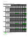
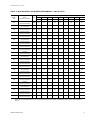
TABLE 7: DNP048 COOLING CAPACITIES - 4 TON
AIR ON EVAPORATOR COIL
TEMPERATURE
OF AIR ON
CONDENSER COIL
1,400 CFM
WB °F
Entering Dry
Bulb °F
85 °F
Sensible Capacity
MBH1
NET CAP.
MBH
TOTAL POWER
INPUT kW
1.
Entering Dry
Bulb °F
Sensible Capacity
MBH1
Entering Dry
Bulb °F
MBH1
Sensible Capacity
Entering Dry
Bulb °F
Sensible Capacity
MBH1
Entering Dry
Bulb °F
MBH1
Sensible Capacity
57
72
67
62
57
45.9
55.2
50.4
46.6
46.9
3.66
3.62
3.57
3.85
3.83
3.79
3.73
43.7
45.6
45.9
39.1
47.7
46.6
46.9
83
80
77
31.7
27.7
23.6
39.6
35.6
31.6
44.6
42.4
38.4
45.3
43.6
39.5
34.5
29.8
25.1
43
38.3
33.7
46.6
45.7
41
46.9
46.9
42.3
74
71
68
19.6
-
27.5
23.5
19.4
34.3
30.3
26.2
35.5
31.4
27.4
20.5
-
29
24.3
19.7
36.3
31.7
27
37.6
32.9
28.3
51.8
46.8
43.8
44.0
51.9
46.9
43.9
44.2
4.07
4.04
4.01
3.99
4.21
4.18
4.15
4.12
35.4
31.4
27.4
23.3
19.3
-
42.9
38.9
34.9
30.8
26.8
22.7
18.7
43.8
42.8
40.9
36.8
32.8
28.7
24.7
44.0
43.2
41.5
37.5
33.4
29.4
25.4
38.4
33.8
29.1
24.4
19.8
-
46.4
41.7
37.1
32.4
27.7
23.1
18.4
43.9
43.9
43.5
38.8
34.1
29.5
24.8
44.2
44.2
44.2
39.5
34.8
30.2
25.5
48.7
44.3
41.4
41.7
49.2
44.7
41.8
42.1
4.49
4.45
4.38
4.34
4.63
4.59
4.51
4.48
34.1
30.0
26.0
22.0
17.8
-
41.3
37.7
33.6
29.6
25.6
21.5
17.5
41.4
40.7
38.9
34.9
30.8
26.8
22.8
41.7
41.1
39.4
35.3
31.3
27.3
23.2
37.1
32.4
27.8
23.1
18.4
-
4.44
40.6
35.9
31.3
26.6
21.9
17.3
41.8
41.8
41.6
36.9
32.3
27.6
22.9
42.1
42.1
42.1
37.4
32.7
28.1
23.4
45.7
41.8
39.1
39.4
46.4
42.5
39.7
40
4.91
4.86
4.74
4.70
5.05
5
4.87
4.83
32.7
28.7
24.6
20.6
16.6
-
39.7
36.5
32.4
28.4
24.4
20.3
16.3
39.1
38.7
37.0
32.9
28.9
24.9
20.8
39.4
38.9
37.2
33.2
29.1
25.1
21.1
35.8
31.1
26.4
21.8
17.1
-
42.5
39.5
34.8
30.1
25.5
20.8
16.2
39.7
39.7
39.7
35
30.4
25.7
21
40
40
40
35.3
30.6
26
21.3
42.7
39.3
36.8
37.0
43.6
40.2
37.6
37.9
4.3
5.3
5.1
5.0
5.5
5.4
5.2
5.2
31.4
27.3
23.3
19.2
15.2
-
38.0
35.3
31.2
27.2
23.1
19.1
15.1
36.8
36.7
35.1
31.0
27.0
22.9
18.9
37.0
36.8
35.1
31.0
27.0
23.0
18.9
34.5
29.8
25.1
20.5
15.8
-
40.5
38.4
33.7
29
24.4
19.7
15
37.6
37.6
37.6
33.2
28.5
23.8
19.2
37.9
37.9
37.9
33.2
28.5
23.9
19.2
86
83
80
77
74
71
68
86
83
80
77
74
71
68
86
83
80
77
74
71
68
NET CAP.
MBH
TOTAL POWER
INPUT kW
125 °F
62
45.6
35.8
NET CAP.
MBH
TOTAL POWER
INPUT kW
115 °F
67
49.2
3.69
NET CAP.
MBH
TOTAL POWER
INPUT kW
105 °F
72
54.0
86
NET CAP.
MBH
TOTAL POWER
INPUT kW
95 °F
1,600 CFM
WB °F
86
83
80
77
74
71
68
These capacities are net capacities (the indoor fan heat is deducted).
ALL SENSIBLE CAPACITY
Unitary Products Group
13
036-21366-007-A-1205
TABLE 8: DNP060 COOLING CAPACITIES - 5 TON
AIR ON EVAPORATOR COIL
TEMPERATURE
OF AIR ON
CONDENSER COIL
1,500 CFM
WB °F
Entering Dry
Bulb °F
85 °F
Sensible Capacity
MBH1
NET CAP.
MBH
TOTAL POWER
INPUT kW
1.
Entering Dry
Bulb °F
Sensible Capacity
MBH1
Entering Dry
Bulb °F
MBH1
Sensible Capacity
Entering Dry
Bulb °F
Sensible Capacity
MBH1
Entering Dry
Bulb °F
MBH1
Sensible Capacity
57
72
67
62
57
53.1
64.3
58.3
53.3
53.7
4.44
4.38
4.27
4.68
4.63
4.57
4.45
47.5
52.7
53.1
41.4
49.6
53.3
53.7
83
80
77
35.0
30.6
26.3
43.2
38.8
34.4
50.9
46.5
42.1
53.1
50.5
46.2
36.1
30.7
25.4
44.3
38.9
33.5
52.0
46.6
41.2
53.7
50.7
45.3
74
71
68
21.9
---
30.0
25.7
21.3
37.7
33.4
29.0
41.8
37.4
33.1
20.0
---
28.2
22.8
17.4
35.9
30.5
25.1
39.9
34.6
29.2
60.6
56.0
52.1
51.5
61.2
56.6
52.6
52.0
4.96
4.90
4.80
4.73
5.12
5.05
4.95
4.88
38.2
33.9
29.5
25.1
20.7
---
46.6
42.2
37.8
33.5
29.1
24.7
20.3
52.1
49.8
45.4
41.1
36.7
32.3
27.9
51.5
51.5
48.7
44.4
40.0
35.6
31.2
43.3
38.0
32.6
27.3
21.9
---
52.6
47.2
41.9
36.5
31.1
25.8
20.4
52.6
52.6
50.3
44.9
39.5
34.2
28.8
52.0
52.0
52.0
46.7
41.3
35.9
30.6
57.6
53.3
49.5
49.3
58.4
54.1
50.2
50.0
5.52
5.43
5.34
5.27
5.69
5.60
5.51
5.43
37.1
32.7
28.4
24.0
19.6
---
45.3
40.9
36.6
32.2
27.8
23.4
19.1
49.5
48.4
44.1
39.8
35.4
31.0
26.6
49.3
49.3
46.4
42.1
37.7
33.3
29.0
42.6
37.2
31.8
26.5
21.1
---
51.8
46.4
41.1
35.7
30.3
25.0
19.6
50.2
50.2
49.1
43.7
38.3
33.0
27.6
50.0
50.0
50.0
44.7
39.3
33.9
28.6
54.6
50.6
46.9
47.1
55.7
51.6
47.9
48.0
6.07
5.97
5.89
5.81
6.26
6.16
6.07
5.99
36.0
31.6
27.2
22.8
18.5
---
44.0
39.7
35.3
30.9
26.5
22.2
17.8
46.9
46.9
42.9
38.5
34.1
29.7
25.4
47.1
47.1
44.2
39.8
35.4
31.0
26.7
41.8
36.4
31.1
25.7
20.3
---
51.0
45.6
40.3
34.9
29.5
24.2
18.8
47.9
47.9
47.9
42.5
37.1
31.8
26.4
48.0
48.0
48.0
42.7
37.3
31.9
26.6
51.6
47.9
44.4
44.9
52.9
49.1
45.5
46.0
6.62
6.51
6.43
6.35
6.82
6.71
6.62
6.54
34.8
30.5
26.1
21.7
17.3
---
42.8
38.4
34.0
29.6
25.3
20.9
16.5
44.4
45.5
41.6
37.2
32.8
28.4
24.1
44.9
44.9
41.9
37.5
33.1
28.7
24.4
41.0
35.6
30.3
24.9
19.6
---
50.2
44.8
39.5
34.1
28.7
23.4
18.0
45.5
45.5
46.7
41.3
35.9
30.6
25.2
46.0
46.0
46.0
40.7
35.3
29.9
24.6
86
83
80
77
74
71
68
86
83
80
77
74
71
68
86
83
80
77
74
71
68
NET CAP.
MBH
TOTAL POWER
INPUT kW
125 °F
62
52.7
39.4
NET CAP.
MBH
TOTAL POWER
INPUT kW
115 °F
67
57.6
4.49
NET CAP.
MBH
TOTAL POWER
INPUT kW
105 °F
72
63.5
86
NET CAP.
MBH
TOTAL POWER
INPUT kW
95 °F
1,800 CFM
WB °F
86
83
80
77
74
71
68
These capacities are net capacities (the indoor fan heat is deducted).
ALL SENSIBLE CAPACITY
14
Unitary Products Group
036-21366-007-A-1205
TABLE 9: TWO TON AIR PERFORMANCE 1
EXTERNAL STAIC PRESSURE - IWG
-
-
-
-
984
443
894
422
751
390
608
358
-
-
-
-
854
297
774
280
695
263
615
246
-
-
-
-
-
-
-
-
LOW
743
243
700
235
657
226
614
218
-
-
-
-
-
-
-
-
-
-
-
-
-
-
CFM
WATTS
309
CFM
WATTS
901
CFM
321
CFM
947
CFM
333
CFM
994
CFM
HI
MED
CFM
WATTS
1.10
CFM
1.00
WATTS
.90
CFM
.80
WATTS
.70
WATTS
.60
WATTS
.50
WATTS
.40
WATTS
.30
WATTS
.20
WATTS
MTR
SPD
.10
CFM
MODEL #
DNP
(Cooling/
Heating)
SIDE SUPPLY AIR PERFORMANCE - 208 VOLT
024
SIDE SUPPLY AIR BLOWER PERFORMANCE - 230 VOLT
024
HI
-
-
-
-
-
-
-
-
-
-
-
-
929
491
809
473
688
454
-
-
-
-
MED
-
-
-
-
999
353
944
338
865
319
785
299
706
280
-
-
-
-
-
-
-
-
LOW
998
372
906
333
813
294
721
255
651
241
-
-
-
-
-
-
-
-
-
-
-
-
BOTTOM SUPPLY AIR BLOWER PERFORMANCE - 208 VOLT
024
HI
-
-
-
-
-
-
-
-
-
-
886
398
805
380
676
351
547
322
-
-
-
-
MED
895
300
853
289
811
278
769
267
697
252
625
237
554
221
-
-
-
-
-
-
-
-
LOW
669
219
630
211
591
204
553
196
-
-
-
-
-
-
-
-
-
-
-
-
-
-
-
-
-
-
836
442
728
425
620
409
-
-
-
-
BOTTOM SUPPLY AIR BLOWER PERFORMANCE - 230 VOLTS
HI
024
1.
-
-
-
-
-
-
-
-
MED
-
-
-
-
899
318
850
304
778
287
707
269
635
252
-
-
-
-
-
-
-
-
LOW
898
335
815
300
732
265
649
230
586
217
-
-
-
-
-
-
-
-
-
-
-
-
Above data includes allowances for a dry evaporator coil, gas heat exchanger and no filters. For additional pressure drops, refer
to Table 12 and 13.
Unitary Products Group
15
036-21366-007-A-1205
TABLE 10: SIDE SUPPLY AIR BLOWER PERFORMANCE - 208/230 VOLTS1
EXTERNAL STATIC PRESSURE - IWG
MODEL #
DNP
CFM
.20
.30
.40
.50
.60
.70
.80
.90
1.0
WATTS
WATTS
WATTS
WATTS
WATTS
WATTS
WATTS
WATTS
WATTS
030
COOLING
(FACTORY SETTING)
1000
248
298
325
365
385
411
470
498
500
030
COOLING
(FIELD SETTING)
1250
342
385
431
474
510
562
614
657
694
030
HEATING (2 TUBE)
(FACTORY SETTING)
850
169
217
237
278
302
334
374
401
431
030
HEATING (3 TUBE)
(FACTORY SETTING)
1100
300
338
378
416
447
493
539
576
609
036
COOLING
(FACTORY SETTING)
1200
354
396
436
511
548
599
641
677
721
036
COOLING
(FIELD SETTING)
1350
442
503
563
606
648
685
721
774
826
036
HEATING (2 TUBE)
(FACTORY SETTING)
700
207
231
254
298
320
349
-
-
-
036
HEATING (3 TUBE)
(FACTORY SETTING)
1250
383
432
478
543
581
628
-
-
-
036
HEATING (4 TUBE)
(FACTORY SETTING)
1350
442
503
563
606
648
685
-
-
-
042
COOLING
(FACTORY SETTING)
1350
410
457
504
575
646
687
729
780
830
042
COOLING
(FIELD SETTING)
1500
450
500
553
641
729
798
830
872
939
042
HEATING (3 TUBE)
(FACTORY SETTING)
1500
450
500
553
641
729
798
830
872
939
042
HEATING (4 TUBE)
(FACTORY SETTING)
1275
388
433
478
545
612
652
691
739
787
048
COOLING
(FACTORY SETTING)
1400
427
476
525
599
673
716
759
812
865
048
COOLING
(FIELD SETTING)
1600
476
532
587
687
786
872
958
994
1030
048
HEATING (3 TUBE)
(FACTORY SETTING)
1525
458
511
564
654
744
814
-
-
-
048
HEATING (4 TUBE)
(FACTORY SETTING)
1600
476
532
587
687
786
872
-
-
-
048
HEATING (5 TUBE)
(FACTORY SETTING)
1600
476
532
587
687
786
872
-
-
-
060
COOLING
(FACTORY SETTING)
1500
439
526
559
636
716
748
816
884
941
060
COOLING
(FIELD SETTING)
1800
659
809
814
946
1001
1053
1124
1176
1180
060
HEATING (3 TUBE)
(FACTORY SETTING)
1500
439
526
559
636
716
748
816
884
941
060
HEATING (4 TUBE)
(FACTORY SETTING)
1700
576
757
788
872
929
979
1000
1121
1188
060
HEATING (5 TUBE)
(FACTORY SETTING)
1700
576
757
788
872
929
979
1000
1121
1188
1.
16
MODE
(COOLING / HEATING)
Above data includes allowances for a dry coil, gas heat exchanger and no filters. For additional pressure drops, refer to Tables 11
and 12.
Unitary Products Group
036-21366-007-A-1205
TABLE 11: BOTTOM SUPPLY AIR BLOWER PERFORMANCE - 208/230 VOLTS1
EXTERNAL STATIC PRESSURE - IWG
MODEL #
DNP
MODE
(COOLING / HEATING)
030
COOLING
(FACTORY SETTING)
030
.20
.30
.40
.50
.60
.70
.80
.90
1.0
WATTS
WATTS
WATTS
WATTS
WATTS
WATTS
WATTS
WATTS
WATTS
1000
248
298
325
365
385
411
470
498
500
COOLING
(FIELD SETTING)
1250
342
385
431
474
510
562
614
657
694
030
HEATING (2 TUBE)
(FACTORY SETTING)
850
169
217
237
278
302
334
374
401
431
030
HEATING (3 TUBE)
(FACTORY SETTING)
1100
300
338
378
416
447
493
539
576
609
036
COOLING
(FACTORY SETTING)
1200
354
396
436
511
548
599
641
677
721
036
COOLING
(FIELD SETTING)
1350
442
503
563
606
648
685
721
774
826
036
HEATING (2 TUBE)
(FACTORY SETTING)
700
207
231
254
298
320
349
-
-
-
036
HEATING (3 TUBE)
(FACTORY SETTING)
1250
383
432
478
543
581
628
-
-
-
036
HEATING (4 TUBE)
(FACTORY SETTING)
1350
442
503
563
606
648
685
-
-
-
042
COOLING
(FACTORY SETTING)
1350
410
457
504
575
646
687
729
780
830
042
COOLING
(FIELD SETTING)
1500
450
500
553
641
729
798
830
872
939
042
HEATING (3 TUBE)
(FACTORY SETTING)
1500
450
500
553
641
729
798
830
872
939
042
HEATING (4 TUBE)
(FACTORY SETTING)
1275
388
433
478
545
612
652
691
739
787
048
COOLING
(FACTORY SETTING)
1400
427
476
525
599
673
716
759
812
865
048
COOLING
(FIELD SETTING)
1600
476
532
587
687
786
872
958
994
1030
048
HEATING (3 TUBE)
(FACTORY SETTING)
1525
458
511
564
654
744
814
-
-
-
048
HEATING (4 TUBE)
(FACTORY SETTING)
1600
476
532
587
687
786
872
-
-
-
048
HEATING (5 TUBE)
(FACTORY SETTING)
1600
476
532
587
687
786
872
-
-
-
060
COOLING
(FACTORY SETTING)
1500
345
487
554
569
654
745
784
835
896
060
COOLING
(FIELD SETTING)
1800
567
663
794
917
948
1015
1048
1155
1175
060
HEATING (3 TUBE)
(FACTORY SETTING)
1500
345
487
554
569
654
745
784
835
896
060
HEATING (4 TUBE)
(FACTORY SETTING)
1700
504
603
698
771
831
1043
1102
1155
1202
060
HEATING (5 TUBE)
(FACTORY SETTING)
1700
504
603
698
771
831
1043
1102
1155
1202
1.
CFM
Above data includes allowances for a dry coil, gas heat exchanger and no filters. For additional pressure drops, refer to Tables 11
and 12.
Unitary Products Group
17
036-21366-007-A-1205
TABLE 12: ADDITIONAL STATIC PRESSURE RESISTANCE - 2, 2-1/2, 3 TON
RESISTANCE, IWG
DESCRIPTION
CFM
500
600
700
800
900
1,000
1,100
1,200
1,300
1,400
1,500
1,600
WET EVAPORATOR COIL
.01
.01
.01
.02
.03
.04
.05
.06
.07
.08
.09
.09
ECONOMIZER1
.00
.00
.00
.01
.01
.01
.01
.02
.03
.04
.05
.06
FILTER FRAME KIT
.01
.02
.04
.06
.08
.10
.13
.16
.17
.18
.19
.20
1.
The pressure through the economizer is greater for 100% outdoor air than for 100% return air. If the resistance of the return air
duct system is less than 0.25 IWG, the unit will deliver less CFM during full economizer operation.
TABLE 13: ADDITIONAL STATIC PRESSURE RESISTANCE - 3-1/2, 4 AND 5 TON
RESISTANCE, IWG
DESCRIPTION
WET EVAPORATOR COIL
ECONOMIZER
1
FILTER FRAME KIT
1.
CFM
1,100
1,200
1,300
1,400
1,500
1,600
1,700
1,800
1,900
2,000
.02
.03
.04
.05
.06
.07
.07
.08
.09
.09
.02
.02
.02
.03
.03
.04
.04
.04
.05
.05
.04
.04
.05
.05
.06
.07
.08
.09
.10
.11
The pressure through the economizer is greater for 100% outdoor air than for 100% return air. If the resistance of the return air
duct system is less than 0.25 IWG, the unit will deliver less CFM during full economizer operation.
NOTE:
HEAT ANTICIPATOR
SHOULD BE SET AT 0.35
AMPS FOR ALL MODELS.
THERMOSTAT
** = Minimum wire size of 18 AWG
wire should be used for all
field installed 24 volt wire.
R
UNIT TERMINAL STRIP
**
R
G
G
Y
Y
W
W
C
C
24 VOLT
TRANSFORMER
PROGRAMMABLE
THERMOSTAT ONLY
FIGURE 3 - FIELD WIRING DIAGRAM CONTROL WIRING
18
Unitary Products Group
036-21366-007-A-1205
C O N T A C T O R
C O N T A C T O R
F IE L D -S U P P L IE D
D IS C O N N E C T
G R O U N D
L U G
R E F E R T O E L E C T R IC A L
D A T A T A B L E S T O S IZ E
T H E D IS C O N N E C T
S IN
P H
P O
S U
G L E
A S E
W E R
P P L Y
F IE L D -S U P P L IE D
D IS C O N N E C T
G R O U N D
L U G
T H R
P H A
P O W
S U P
R E F E R T O E L E C T R IC A L
D A T A T A B L E S T O S IZ E
T H E D IS C O N N E C T
E E
S E
E R
P L Y
FIGURE 4 - POWER WIRING FIELD DIAGRAM
TABLE 14: ELECTRICAL DATA
VOLTAGE
LIMITATIONS1
SUPPLY
AIR
BLOWER
MOTOR
FLA
MINIMUM
CIRCUIT
AMPACITY
MAX.
FUSE
SIZE,
AMPS2
MAX.
HACR
BREAKER
SIZE,
AMPS
RLA
LRA
COND.
FAN
MOTOR,
FLA
253
8.0
53.5
1.1
2.6
16.5
20
20
0.96
40
253
13.6
67
1.1
6.8
24.9
35
35
0.96
40
187
253
8.6
55
1.1
6.8
18.7
25
25
0.96
75
432
504
5.7
39
0.6
6.8
13.4
20
20
0.96
75
208/230-1-60
187
253
17.2
88
1.1
6.8
29.4
45
45
0.96
40
036
208/230-3-60
187
253
11.4
77
1.1
6.8
22.2
30
30
0.96
75
036
460-3-60
432
504
5.7
39
0.6
6.8
14.8
20
20
0.96
75
036
575-3-60
540
630
4.7
31
0.6
6.8
13.3
20
20
0.96
75
042
208/230-1-60
187
253
20
104
1.3
9.1
35.4
50
50
0.96
40
042
208/230-3-60
187
253
13.9
88
1.3
9.1
27.8
40
40
0.96
75
042
460-3-60
432
504
6.4
44
0.7
9.1
18.5
25
25
0.96
75
042
575-3-60
540
630
5.4
34
0.6
9.1
16.8
25
25
0.96
75
048
208/230-1-60
187
253
23.4
126
1.9
9.1
39.5
60
60
0.96
40
048
208/230-3-60
187
253
13
93
1.9
9.1
26.5
35
35
0.96
75
048
460-3-60
432
504
6.4
46.5
1.0
9.1
18.4
25
25
0.96
75
048
575-3-60
540
630
5.1
37.2
0.8
9.1
17.3
25
25
0.96
75
060
208/230-1-60
187
253
25
150
2.8
9.1
43.2
60
60
0.96
40
060
208/230-3-60
187
253
17.3
123
2.8
9.1
33.5
45
45
0.96
75
060
460-3-60
432
504
8.4
70
2.8
9.1
22.6
30
30
0.96
75
060
575-3-60
540
630
7.0
53
2.8
9.1
21.2
30
30
0.96
75
MODEL
DNP
POWER SUPPLY
024
030
MIN.
MAX.
208/230-1-60
187
208/230-1-60
187
030
208/230-3-60
030
460-3-60
036
COMPRESSOR
1.
Rated in accordance with ARI Standard 110, utilization range “A”.
2.
Dual element, time delay type.
Unitary Products Group
UNIT
POWER
FACTOR
TRANSFORMER
SIZE (VA)
19
036-21366-007-A-1205
VENTAIROUTLETHOOD
BLOWERSERVICE
ACCESSCOMPA RTMENT
GAS SUPPLY1-1/4"DIA.PANEL
HOLE(1/2"N PTI
CONNECTION)
CONDENSERCOIL
UNITCONDENSATE
CONNECTION3/4"NPTI
(TRAPRECOMMENDED)
A
2-3/8
HIGHVOLTAGE
CONN.1-3/8"DIA.
KNOCKOUT
HIGHVOLTAGE
CONN.7/8"DIA.
KNOCKOUT
B
3-3/4
REFRIGERAN T
CONNECTIONS
COMBU STIONAIR
INLETLOUVERS
FRONT
2-1/2
GAS SUPPLY1-1/4"DIA.
KNOCKOUT(1/2"NPTI
CONNECTION)
LOWVOLTAGECONN.
1-3/8"DIA.KNOCKOUT
X7/8"HOLE
5-3/8
1-1/2
11
12-3/4
47-1/4
(OVERALL)
3-1/3
2-5/8
GAS /ELECTRICC ONTROL
SERVICEACCESS
(OVERALL) COMPA RTMENTPA NEL
49-1/8
All dimensions are in inches.
They are subject to change without notice. Certified dimensions
will be provided upon request.
FIGURE 5 - UNIT DIMENSIONS - FRONT
TABLE 15: UNIT DIMENSIONS FRONT
TABLE 16: UNIT MINIMUM CLEARANCES1 2
DIMENSION
CLEARANCES
UNIT SIZE
“A”
“B”
FRONT
36”
024, 030, 036
33-1/2
18-1/4
BACK
0”
042, 048, 060
41-1/2
23-1/8
LEFT SIDE (Filter-Access)
24”
RIGHT SIDE
12”
BELOW
UNIT3
ABOVE UNIT 4
20
0”
36” (For Condenser Air Discharge)
1.
A 1” clearance must be provided between any combustible material and the supply air ductwork.
2.
The products of combustion must not be allowed to
accumulate within a confined space and recirculate.
3.
Units may be installed on combustible floors made from
wood or class A, B, or C roof covering material.
4.
Units must be installed outdoors. Overhanging structures or shrubs should not obstruct condenser air discharge outlet.
Unitary Products Group
036-21366-007-A-1205
HIGH VOLTAGE
CONN. 1-3/32" DIA.
KNOCKOUT
8-7/8
11-7/8
19-1/4
FRONT
GAS SUPPLY 1-5/8" DIA.
KNOCKOUT (1/2" NPTI
CONNECTION)
LOW VOLTAGE CONN.
7/8 " DIA. KNOCKOUT
4-5/8
CONDENSATE
DRAIN 3/4"' NPTI
26-3/4
6
FIGURE 6 - UNIT DIMENSIONS - FRONT & BOTTOM
S ID E S U P P L Y
A IR O P E N IN G
1 4 -1 /2
2 8 -3 /8
C O N D E N S E R
C O IL
1 4 -1 /2
B A C K
B O T T O M S U P P L Y
A IR O P E N IN G
3 -3 /8
S ID E R E T U R N
A IR O P E N IN G
1 4 -1 /2
4
1 -3 /4
3 -1 /2
1 5
1 5
1 -3 /4
1 5
2 9 -9 /1 6
B O T T O M R E T U R N
A IR O P E N IN G
3 -1 /2
1 -3 /4
FIGURE 7 - UNIT DIMENSIONS - BACK & BOTTOM
Unitary Products Group
21
036-21366-007-A-1205
F IE L D S U P P L IE D
D IS C O N N E C T S W IT C H
L O C A T E D T O R E A R O F U N IT
T O
P O W E R
C O N T R O L W IR IN G
T O IN D O O R
T H E R M O S T A T
S U P P Y
R E T U R N A IR
D U C T
S U P P L Y A IR
D U C T
T O G A S
S U P P L Y L IN E
M A N U A L G A S
S H U T -O F F V A L V E
FIGURE 8 - TYPICAL SLAB ON GROUND INSTALLATION
M A N U A L G A S
S H U T -O F F V A L V E
S U
D IS C
S
M O
O
T O
F IE L D
P P L IE D
O N N E C T
W IT C H
U N T E D
N U N IT
P O W E R
S U P P L Y
T O G A S
S U P P L Y L IN E
T O
C O N T R O L W IR IN G
IN D O O R T H E R M O S T A T
R E T U R N A IR
D U C T
S U P P L Y A IR
D U C T
FIGURE 9 - TYPICAL ROOF CURB INSTALLATION
22
Unitary Products Group
036-21366-007-A-1205
R O O F C U R B
IN S T A L L A T IO N
R E A R D U C T
R O O F C U R B
IN S T A L L A T IO N
B O T T O M D U C T
S L A B O N G R O U N D
IN S T A L L A T IO N
FIGURE 10 - TYPICAL DUCT APPLICATIONS
TABLE 17: UNIT WEIGHTS AND CENTER OF GRAVITY
UNIT
SIZE
SHIPPING
WEIGHT
(lbs.)
CORNER WEIGHTS
(location, lbs.)
OPERATING
WEIGHT
(lbs.)
“A”
ECONOMIZER
(lbs.)
“B”
“C”
024, 030, 036
400
395
100
96
98
101
“D”
042, 048, 060
475
470
133
130
102
104
40
ROOF
CURB
(lbs.)
8” - 70
14” - 75
"D"
CENTER OF
GRAVITY
FRONT
OF
UNIT
"C"
"A"
49-1/8
25
"B"
25
47-1/4
FIGURE 11 - UNIT CENTER OF GRAVITY
Unitary Products Group
23
036-21366-007-A-1205
R E C O M M E N D E D
D U C T S IZ E
1 7 -1 /2 " X 1 6 -3 /4 "
4 2 -2 /3
4 0 -3 /4
1 7 -5 /8
3 -1 /2
1 7 -1 /4
4 5 -1 /8
4 3 -1 /4
O P E N IN G F O R
R E T U R N A IR D U C T
2 2
1
O P E N IN G F O R
S U P P L Y A IR D U C T
R E C O M M E N D E D
D U C T S IZ E
1 7 -1 /8 " X 2 1 -1 /2 "
1 4
FIGURE 12 - ROOF CURB DIMENSIONS1
1 "
3 /4 " X 1 " W ID E G A S K E T IN G F O R C U R B F R A M E
A N D A L L D U C T S U P P O R T S U R F A C E S
U N IT B A S E
U N IT B A S E R A IL
W O O D N A IL E R
C O U N T E R F L A S H IN G
8 " M IN . A B O V E F IN IS H E D R O O F
1 4 "
C A N T S T R IP
C U R B F R A M E
IN S U L A T IO N A N D R O O F IN G
M A T E R IA L
IN S U L A T IO N
R O O F D E C T A N D R O O F IN G
M A T E R IA L
FIGURE 13 - ROOF CURB CROSS SECTION
1. 8” Roof curb also available
24
Unitary Products Group
036-21366-007-A-1205
FIGURE 14 - TYPICAL WIRING DIAGRAM D*NP 024 (208/230-1-60 POWER SUPPLY)
Unitary Products Group
25
26
FAN
RC1/RC2
BRN
205/R
206/R
LS
C
101/BK
102/Y
R
COMPR
S
103/BR
LP
HP
FS
211/PR
208/PR
213/R
204/O
RS
PS
205/R
213/R
ALS
805/BL
801/BL
806/BR
G
C
B
A
TB2
200/R
230
107/PR
A
M1
B
A
M2
B
B
801/BL
7
2
209/BK
1
804/BK
805/BL
803/BK
802/BK
803/BK
804/BK
S2
210/BL
207/Y
3
2
211/PR
4
GAS VALVE
2
5
3
6
CN1
EAC
4
1
204/O
N
N
OUTDOOR
FAN
MOTOR
2
W1/
WHT
DRAFT
MOTOR
PRP
BLU
CLEAR
BLU
3
4
5
9
11
HEAT
/BLK
10
13
R/RED
12
14
6
Y1/
YEL
HSP
200/R
201/BR
C1/BRN
214/BR
221/BR
220/O
224/R
213/R
C2/ COOL
BRN /BLU
BLK
C
XFMR
X
4
3
2
1
LEADS
MOTOR
UNUSED
DI
214/BR
GRN
ID MOTOR CONTROLLER
1
C1/
BLK BRN
BLK
BLU
BLU
CLEAR
202/Y
800/Y
C
BLK
101/BK
104/R
102/Y
BLK
PRP
CONTROL BOX
201/BR
HUM
S
802/BK
BLK BRN PRP
CCH
2
1
SEC
T1
208
100/BK
C2/BRN
207/Y
HEAT
COOL
T1
T2
T1
T2
206/R
209/BK
210/BL
S3
1
2
3
4
GAS HEAT SECTION
A
LR
(SEE NOTE 5)
208/PR
W1/WHT
Y1/YEL
CONTROL BOARD
224/R
PRP
103/BR
800/Y
R
W
Y
L1
L2
L1
L2
15
7
BLK
BLK
BLK
M1-2
16
S4
8
30
29
28
27
ALS
ASCT
LEGEND:
LOCK OUT RELAY (OPTIONAL ACCESSORY)
150
175
160
270
160
160
LS
ALS
RS
LS
ALS
160
200
ALS
RS
160
270
270
140
RS
LS
LS
140
160
LS
ALS
ALS
RS
160
200
160
LS
ALS
RS
160
270
ALS
RS
270
160
160
200
140
160
160
ALS
RS
LS
160
270
LS
RS
LS
ALS
200
140
ALS
RS
CCH
T1
TB2
5
4
3
2
1
S5
240V/BLK
240V/PRP
GND/GRN
OPTIONAL WIRING AND DEVICES
FIELD WIRING
CRANKASE HEATER (OPTIONAL)
FACTORY WIRING AND DEVICES
ROOM THERMOSTAT 24V CONNECTIONS
TB1 ON CONTROL BOARD
TRANSFORMER, 24V, 40 VA
TERMINAL BLOCK, 24V, ID
MOTOR "SPEED" CONNECTIONS
IDENTIFIED TERMINAL ON CAPACITOR
OPEN
130
---
---
145
---
-----
120
-----
--110
110
---
-----
130
-----
--130
--110
---
---
130
-----
--110
CLOSE
MOTOR
ID FAN
12
12
6
12
12
12
6
12
12
6
12
6
12
12
12
6
12
12
6
12
6
12
12
6
12
12
12
6
12
6
+/-
C
D
INDOOR BLOWER COOL ON DELAY: 3 SEC
INDOOR BLOWER COOL OFF DELAY: 30 SEC
CONTROL BOARD SETTINGS:
COMBUSTION BLOWER POSTPURGE: 5 SEC
4
1
204/O
2
213/R
R/RED
Y
C
3
RS
2
1
S
5
P1
206/R
ALS
209/BK
207/Y
208/PR
210/BL
X
C
XFMR
4
3
2
1
LEADS
MOTOR
UNUSED
DI
202/Y
203/BR
HEAT/BK
120 SEC
FACTORY
SETTING
60 SEC
205/R
200/R
201/BR
221/BR
M2
220/O
224/R
COOL/BLU
CONTROL
BOARD
CN1
213/R
6
HEAT
COOL
N
N
EAC
HUM
SEE TABLE 1
FOR COOLING BLOWER
"SPEED" CONNECTIONS
E
S3/P3
S4/P4
S5/P5
-042
-042
-048
-048
-030
-030
-036
-036
UNIT SIZE
1400 (ARI RATING)
1600
1350 (ARI RATING)
1500
1200 (ARI RATING)
1350
1000 (ARI RATING)
1250
FOR COOLING
AIRFLOW
(CFM)
TABLE 1
BLOWER CONNECTIONS
FOR COOLING AIRFLOW
TB2-B
TB2-A
TB2-B
TB2-B
TB2-A
TB2-B
TB2-A
CONNECT
WIRE
COOL/BLU TO:
TB2-A
SOCKET/PLUG CONNECTION, 24V, 4 PIN ON GAS VALVE
SOCKET/PLUG CONNECTION, 24V, 16 PIN ON ID MOTOR CONTROL
SOCKET/PLUG CONNECTION, 230V, 5 PIN ON ID MOTOR CONTROL
CN1/P1 SOCKET/PLUG CONNECTION, 24V, 6 PIN ON CONTROL BOARD
S2/P2 SOCKET/PLUG CONNECTION, 24V, 4 PIN ON GAS VALVE
9
---
---
9
---
-----
9
-----
--9
9
---
-----
9
-----
--9
--9
---
---
9
-----
--9
+/-
R
W
Y
G
C
TB1
B
A
TB2
INDOOR BLOWER HEAT ON DELAY: 30 SEC
INDOOR BLOWER HEAT OFF DELAY: (SEE RIGHT)*
* BLACK SQUARE INDICATES SWITCH POSITION
CONTROL SETPOINT (DEG F)
RS
LS
DEVICE
LIMIT SWITCH
CONTACTOR, COMPR & OD FAN
CONTACTOR, DRAFT INDUCER MOTOR
PRESSURE SWITCH - MAKES @
.193 IWC NOM (.33 IWC MAX)
RC1/RC2 COMP. START & OUTDOOR FAN RUN CAPACITOR
RS
ROLLOUT SWITCH
LS
M1
M2
PS
LR
HEAT
OFF
COOL
Y
AUTO
ON
B
TEMPERATURE CONTROLS
COMPR COMPRESSOR
EAC
ELECTRONIC AIR CLEANER RELAY OUTPUT
ON CONTROL BOARD, 24-1-60, 18VA MAX
FS
FREEZESTAT SWITCH (OPTIONAL ACCESSORY)
OPEN @ 26 DEGREE F
HP
HIGH PRESSURE SWITCH (OPTIONAL
ACCESSORY) OPENS @ 380 PSIG
HSP
HOT SURFACE TO PILOT
HUM
HUMIDIFIER RELAY OUTPUT ON CONTROL
BOARD, 24-1-60, 18VA MAX
LP
LOW PRESSURE SWITCH (OPTIONAL ACCESSORY)
OPEN @ 7 PSIG
AUXILARY LIMIT SWITCH
ANTI-SHORT CYCLE TIMER
(OPTIONAL ACCESSORY)
5 TUBE
048
3 TUBE
048
4 TUBE
042
3 TUBE
042
4 TUBE
036
3 TUBE
036
2 TUBE
036
3 TUBE
030
2 TUBE
030
UNIT SIZE
4 TUBE
048
L2
L1
T1
L1
W
G
26
7
T2
BLK
DETAIL "A"
L2
CCH
D/P CONFIGURATION
CCH
S/P CONFIGURATION
OPTIONAL CCH
R
ROOM
THERMOSTAT
25
24
23
22
21
20
19
18
17
16
15
14
13
12
11
10
9
8
7
6
5
4
3
2
1
A
ELEMENTARY DIAGRAM
OFF
807/BL
2
3
ASCT
(SEE NOTE 5)
G/GRA
Y
TB1
C
202/Y
OFF
1
HERM
203/BR
220/O
221/BR
202/Y
(SEE NOTE 5)
DELAY
203/BR
213/R
R/RED
SEE TABLES 1 AND 2
FOR HEATING AND
COOLING BLOWER
"SPEED" CONNECTIONS
C
100/BK
110/BK
107/PR
108/PR
110/BK
240V/BLK
108/PR
240V/PRP
104/R
GND
LUG
CONNECTION DIAGRAM
DELAY
ON
NEUTRAL
COOLING UNIT WITH GAS HEAT
LS
6
12
2
3
1
11
5
P4/S4
PS
2
1
3
4
T1
T2
T2
T1
M2-1
M2-2
B
P2
GAS
2
S3
1
3
3
VALVE
4
1
4
S2
2
RC1
RC2
FS
100/BK
PRP
BRN
BLK
102/Y
103/BR
101/BK
110/BK
107/PR
P3
BLU
BLU
1
S
K
230V
LP
201/BR
ID FAN
MOTOR
230-1-60
110/BK
804/BK
801/BL (SEE NOTE 5)
806/BR
ID MOTOR CONTROLLER
240V/PR
L1
L2
A LR
HP
J
C
T1
1
L
100/BK
CAUTION - OPEN ALL DISCONNECTS
BEFORE SERVICING THIS UNIT
035-18578D000
REV. C
7. SHUNT CONTACT ALSO USED WITH CRANKCASE HEATER. (OPTIONAL)
6. UNIT FACTORY WIRED FOR 230 VOLT OPERATION. FOR 208 VOLT OPERATION
MOVE '108/PR' WIRE FROM 230V TO 208V ON TRANFORMER T1.
PRI
208V
SEC 24V
75 VA
5. IF BOTH LR AND ASCT ARE PRESENT, WIRE 801/BL AND 805/BL ARE CONNECTED TO ASCT-3.
IF LR ONLY IS PRESENT, WIRE 801/BL AND 805/BL ARE CONNECTED TO M1 COIL. IF ASCT
ONLY IS PRESENT WIRE 202/Y IS CONNECTED TO ASCT-3. IF NEITHER LR OR ASCT ARE
PRESENT, WIRE 202/Y IS CONNECTED TO M1 COIL.
3. MOTORS ARE INHERENTLY PROTECTED.
4. SEE UNIT NAMEPLATE FOR MAXIMUM FUSE SIZE AND MINIMUM CIRCUIT AMPACITY.
2
ASCT
107/PR
3
805/BL
(SEE NOTE 5)
1
OD FAN
MOTOR
230-1-60
1
COMPR
230-1-60
HSP
R
C
(OPTIONAL ACCESSORIES - SEE NOTE 5)
803/BK
104/R
807/BL
H
240V/BK
BLK
PRP
802/BK
M1
M1-2
M1-1
GRN
211/PR
S5/P5
5
L2
L1
108/PR
800/Y
LR
DRAFT
MOTOR
230-1-60
G
NOTES:
1. ALL FIELD WIRING TO BE ACCOMPLISHED FOLLOWING CITY, LOCAL AND/OR NATIONAL
CODES IN EFFECT AT TIME OF INSTALLATION OF THIS UNIT.
2. CAUTION: LABEL ALL WIRES PRIOR TO DISCONNECTION WHEN SERVICING
CONTROLS. WIRING ERRORS CAN CAUSE IMPROPER AND DANGEROUS OPERATION.
IF ANY OF THE WIRE AS SUPPLIED WITH THIS UNIT MUST BE REMOVED,
IT MUST BE REPLACED WITH TYPE 105 DEGREE C, 600V WIRE OR EQUIVALENT
CLEARLY RENUMBERED FOR IDENTIFICATION. VERIFY PROPER OPERATION
AFTER SERVICING.
224/R
214/BR
Y1/YEL
R/RED
W1/WHT
C2/BRN
C1/BRN
HEAT/BLK
COOL/BLU
7
GND
LUG
108/PR
SEE DETAIL "A"
POWER SUPPLY
208/230-1-60
180 SEC
90 SEC
F
17H
15H
10G
3H,5H
036-21366-007-A-1205
FIGURE 15 - TYPICAL WIRING DIAGRAM D*NP 030-048 (208/230-1-60 POWER SUPPLY)
Unitary Products Group
036-21366-007-A-1205
FIGURE 16 - TYPICAL WIRING DIAGRAM D*NP 060 (208/230-1-60 POWER SUPPLY)
Unitary Products Group
27
28
PRP
105/BL
BRN
110/BK
100/BK
107/PR
108/PR
224/R
805/BL
801/BL
806/BR
205/R
206/R
RS
LS
121/BK
126/Y
L3
L1
L2
COMPR
123/BL
211/PR
208/PR
213/R
204/O
PS
205/R
213/R
ALS
2
LP
HP
FS
B
801/BL
7
2
1
804/BK
805/BL
803/BK
802/BK
803/BK
804/BK
T1
208
2
1
2
5
3
6
CN1
EAC
4
1
204/O
N
N
OUTDOOR
FAN
MOTOR
BLK BRN PRP
BLU
BLU
2
W1/
WHT
DRAFT
MOTOR
PRP
3
BLU
9
HEAT
/BLK
10
11
4
R/RED
12
HSP
212/R
201/BR
C1/BRN
214/BR
221/BR
220/O
5
13
14
6
COOL Y1/
/BLU
YEL
BLU
CLEAR
C2/
BRN
BLK
C
XFMR
X
4
3
2
1
LEADS
MOTOR
UNUSED
DI
224/R
213/R
214/BR
GRN
121/BK
BK
123/BL
105/BL
126/Y
ID MOTOR CONTROLLER
1
C1/
BRN
CLEAR
202/Y
800/Y
802/BK
C
BLK
PRP
CONTROL BOX
201/BR
HUM
S
SEC
100/BK
C2/BRN
207/Y
HEAT
COOL
T1
T2
T3
T1
T2
206/R
209/BK
210/BL
S3
209/BK
S2
1
3
4
2
207/Y
210/BL
211/PR
3
2
4
GAS VALVE
GAS HEAT SECTION
A
LR
(SEE NOTE 5)
208/PR
W1/WHT
Y1/YEL
800/Y
R
W
Y
200/R
230
107/PR
M1
A
M2
B
CONTROL BOARD
L1
L2
L3
L1
L2
7
15
16
S4
8
30
29
28
27
26
25
24
23
22
21
20
19
18
17
16
15
14
13
12
11
10
9
8
7
6
5
4
3
2
1
270
160
160
270
RS
LS
ALS
RS
270
175
160
270
160
160
RS
LS
ALS
RS
LS
ALS
12
12
12
6
12
6
12
12
12
6
12
6
12
12
12
6
12
6
12
12
6
12
12
6
12
12
6
12
12
6
---
130
145
-----
---
---
120
110
-----
---
----110
---
130
---
---
--130
110
---
---
--130
---
---
110
---
AUXILARY LIMIT SWITCH
ANTI-SHORT CYCLE TIMER
(OPTIONAL ACCESSORY)
LEGEND:
150
160
LS
ALS
140
160
200
270
LS
ALS
RS
RS
160
140
160
LS
ALS
160
200
140
160
200
RS
LS
270
160
160
RS
LS
ALS
ALS
RS
LS
ALS
140
160
200
CONTROL SETPOINT (DEG F)
OPEN
+/CLOSE
LS
ALS
RS
DEVICE
TEMPERATURE CONTROLS
W
G
---
9
9
-----
---
---
9
9
-----
---
----9
---
9
---
---
--9
9
---
---
--9
---
---
9
---
+/-
HEAT
OFF
COOL
Y
AUTO
ON
HOT SURFACE TO PILOT
HUMIDIFIER RELAY OUTPUT ON CONTROL
BOARD, 24-1-60, 18VA MAX
LOW PRESSURE SWITCH (OPTIONAL ACCESSORY)
OPEN @ 7 PSIG
LOCK OUT RELAY (OPTIONAL ACCESSORY)
5
4
3
2
1
S5
240V/BLK
240V/PRP
GND/GRN
FIELD WIRING
LIMIT SWITCH
CONTACTOR, COMPR & OD FAN
CONTACTOR, DRAFT INDUCER MOTOR
PRESSURE SWITCH - MAKES @
.193 IWC NOM (.33 IWC MAX)
RC2
OUTDOOR FAN RUN CAPACITOR
RS
ROLLOUT SWITCH
T1
TRANSFORMER, 24V, 75 VA
TB2
TERMINAL BLOCK, 24V, ID
MOTOR "SPEED" CONNECTIONS
IDENTIFIED TERMINAL ON CAPACITOR
ROOM THERMOSTAT 24V CONNECTIONS
TB1 ON CONTROL BOARD
FACTORY WIRING AND DEVICES
OPTIONAL WIRING AND DEVICES
LS
M1
M2
PS
LR
LP
HSP
HUM
CB
CIRCUIT BREAKER
COMPR COMPRESSOR
EAC
ELECTRONIC AIR CLEANER RELAY OUTPUT
ON CONTROL BOARD, 24-1-60, 18VA MAX
FS
FREEZESTAT SWITCH (OPTIONAL ACCESSORY)
OPEN @ 26 DEGREE F
HP
HIGH PRESSURE SWITCH (OPTIONAL
ACCESSORY) OPENS @ 380 PSIG
ALS
ASCT
5 TUBE
048
4 TUBE
048
3 TUBE
048
4 TUBE
042
3 TUBE
042
4 TUBE
036
3 TUBE
036
2 TUBE
036
3 TUBE
030
2 TUBE
030
R
ROOM
THERMOSTAT
UNIT SIZE
A
B
MOTOR
ID FAN
ELEMENTARY DIAGRAM
C
D
1
204/O
2
213/R
R/RED
Y
C
3
RS
2
1
S
5
P1
CN1
213/R
6
HEAT
COOL
N
N
EAC
HUM
206/R
ALS
209/BK
207/Y
208/PR
210/BL
X
C
XFMR
4
3
2
1
LEADS
MOTOR
UNUSED
DI
202/Y
205/R
212/R
201/BR
221/BR
M2
220/O
224/R
COOL/BLU
CONTROL
BOARD
203/BR
FACTORY
SETTING
120 SEC
60 SEC
HEAT/BK
E
-042
-048
-048
-030
-036
-036
-042
-030
UNIT SIZE
FOR COOLING
AIRFLOW
(CFM)
1400 (ARI RATING)
1600
1350 (ARI RATING)
1500
1200 (ARI RATING)
1350
1000 (ARI RATING)
1250
TB2-B
TB2-A
TB2-B
TB2-B
TB2-A
TB2-B
TB2-A
CONNECT
WIRE
COOL/BLU TO:
TB2-A
SOCKET/PLUG CONNECTION, 230V, 5 PIN ON ID MOTOR CONTROL
S5/P5
TABLE 1
BLOWER CONNECTIONS
FOR COOLING AIRFLOW
SOCKET/PLUG CONNECTION, 24V, 4 PIN ON GAS VALVE
SOCKET/PLUG CONNECTION, 24V, 16 PIN ON ID MOTOR CONTROL
S3/P3
S4/P4
CN1/P1 SOCKET/PLUG CONNECTION, 24V, 6 PIN ON CONTROL BOARD
S2/P2 SOCKET/PLUG CONNECTION, 24V, 4 PIN ON GAS VALVE
4
R
W
Y
G
C
TB1
B
A
TB2
SEE TABLE 1
FOR COOLING BLOWER
"SPEED" CONNECTIONS
* BLACK SQUARE INDICATES SWITCH POSITION
INDOOR BLOWER HEAT ON DELAY: 30 SEC
INDOOR BLOWER HEAT OFF DELAY: (SEE RIGHT)*
INDOOR BLOWER COOL ON DELAY: 3 SEC
INDOOR BLOWER COOL OFF DELAY: 30 SEC
CONTROL BOARD SETTINGS:
COMBUSTION BLOWER POSTPURGE: 5 SEC
OFF
807/BL
1
3
ASCT
(SEE NOTE 5)
212/R
C
G
TB1
200/R
Y
G/GRA
C
OFF
202/Y
CB
B
A
A
B
220/O
221/BR
TB2
DELAY
203/BR
213/R
R/RED
SEE TABLES 1 AND 2
FOR HEATING AND
COOLING BLOWER
"SPEED" CONNECTIONS
RC2
202/Y
(SEE NOTE 5)
110/BK
240V/BLK
108/PR
240V/PRP
203/BR
GND
LUG
CONNECTION DIAGRAM
DELAY
ON
NEUTRAL
COOLING UNIT WITH GAS HEAT
LS
6
12
2
3
1
11
5
PS
2
1
3
4
5
L3
L2
L1
M1
M1-3
M1-2
M1-1
211/PR
240V/PRP
L1
L2
LR
M2-1
M2-2
A
HP
807/BL
P2
GAS
2
S3
1
3
3
VALVE
4
1
4
S2
2
CB
J
RC2
100/BK
PRP
BRN
BLK
126/Y
123/BL
121/BK
110/BK
107/PR
L2
K
B
FS
P3
3.2 AMP
BLU
BLU
200/R
1
230V
LP
201/BR
ID FAN
MOTOR
230-1-60
110/BK
804/BK
801/BL (SEE NOTE 5)
806/BR
803/BK
C
T1
1
L
100/BK
CAUTION - OPEN ALL DISCONNECTS
BEFORE SERVICING THIS UNIT
035-18845D000
REV.C
6. UNIT FACTORY WIRED FOR 230 VOLT OPERATION. FOR 208 VOLT OPERATION
MOVE '108/PR' WIRE FROM 230V TO 208V ON TRANFORMER T1.
PRI
208V
SEC 24V
75 VA
5. IF BOTH LR AND ASCT ARE PRESENT, WIRE 801/BL AND 805/BL ARE CONNECTED TO ASCT-3.
IF LR ONLY IS PRESENT, WIRE 801/BL AND 805/BL ARE CONNECTED TO M1 COIL. IF ASCT
ONLY IS PRESENT WIRE 202/Y IS CONNECTED TO ASCT-3. IF NEITHER LR OR ASCT ARE
PRESENT, WIRE 202/Y IS CONNECTED TO M1 COIL.
3. MOTORS ARE INHERENTLY PROTECTED.
4. SEE UNIT NAMEPLATE FOR MAXIMUM FUSE SIZE AND MINIMUM CIRCUIT AMPACITY.
2
ASCT
107/PR
3
805/BL
(SEE NOTE 5)
1
OD FAN
MOTOR
230-1-60
3
COMPR
230-3-60
HSP
L3
L1
(OPTIONAL ACCESSORIES - SEE NOTE 5)
105/BL
ID MOTOR CONTROLLER
GRN
T1
T2
T3
T2
T1
H
240V/BLK
BLK
PRP
802/BK
108/PR
800/Y
LR
DRAFT
MOTOR
230-1-60
P4/S4
7
108/PR
GND
LUG
G
NOTES:
1. ALL FIELD WIRING TO BE ACCOMPLISHED FOLLOWING CITY, LOCAL AND/OR NATIONAL
CODES IN EFFECT AT TIME OF INSTALLATION OF THIS UNIT.
2. CAUTION: LABEL ALL WIRES PRIOR TO DISCONNECTION WHEN SERVICING
CONTROLS. WIRING ERRORS CAN CAUSE IMPROPER AND DANGEROUS OPERATION.
IF ANY OF THE WIRE AS SUPPLIED WITH THIS UNIT MUST BE REMOVED,
IT MUST BE REPLACED WITH TYPE 105 DEGREE C, 600V WIRE OR EQUIVALENT
CLEARLY RENUMBERED FOR IDENTIFICATION. VERIFY PROPER OPERATION
AFTER SERVICING.
224/R
214/BR
Y1/YEL
R/RED
W1/WHT
C2/BRN
C1/BRN
HEAT/BLK
COOL/BLU
POWER SUPPLY
208/230-3-60
180 SEC
90 SEC
F
17H
15H
10G
3H,5H
036-21366-007-A-1205
FIGURE 17 - TYPICAL WIRING DIAGRAM D*NP 030-048 (208/230-3-60 POWER SUPPLY)
Unitary Products Group
036-21366-007-A-1205
FIGURE 18 - TYPICAL WIRING DIAGRAM D*NP 060 (208/230-3-60 POWER SUPPLY)
Unitary Products Group
29
036-21366-007-A-1205
FIGURE 19 - TYPICAL WIRING DIAGRAM D*NP 030-048 (460/575-3-60 POWER SUPPLY)
30
Unitary Products Group
036-21366-007-A-1205
FIGURE 20 - TYPICAL WIRING DIAGRAM D*NP 060 (460/575-3-60 POWER SUPPLY)
Unitary Products Group
31
036-21366-007-A-1205
TYPICAL WIRING DIAGRAM NOTES
1.
All field wiring to be accomplished following city, local
and/or national codes in effect at time of installation of
this unit.
2.
Caution: Label all wires prior to disconnection when servicing controls. Wiring errors can cause improper and
dangerous operation if any of the wire as supplied with
this unit must be removed it must be replaced with type
105°C, 600V wire or equivalent clearly renumbered for
identification. Verify proper operation after servicing.
3.
Motors are inherently protected.
4.
See unit nameplate for maximum fuse size and minimum
circuit ampacity.
5.
Select indoor blower cooling speed from unit wiring diagram Table 1. Heating speed is preset at the factory.
6.
If both LR and ASCT are present, wire 801/BL and 805/
BL are connected to ASCT-3 if LR only is present wire
801/BL and 805/BL are connected to M1 coil. If ASCT
only is present wire 202/Y is connected to ASCT-3. If
neither LR or ASCT are present, Wire 202/Y is connect
to M1 coil.
7.
Shunt contact also used with crankcase heater.
(Optional).
Open all disconnects before servicing this unit.
LEGEND :
AUXILLARY LIMIT SWITCH
ANTI-SHORT CYCLE TIMER
(OPTIONAL ACCESSORY)
COMPR COMPRESSOR
EAC
ELECTRIC AIR CLEANER RELAY OUTPUT
ON CONTROL BOARD, 24-1-60, 18VA MAX.
FREEZESTAT SWITCH (OPTIONAL ACCESSORY)
FS
OPEN @ 250 F
HP
HIGH PRESSURE SWITCH (OPTIONAL
ACCESSORY) OPENS @ 380 PSIG
HSP
HOT SURFACE TO PILOT
HUM
HUMIDIFER RELAY OUTPUT ON CONTROL
BOARD, 24-1-60, 18VA MAX.
LP
LOW PRESSURE SWITCH (OPTIONAL ACCESSORY)
OPEN @ 7 PSIG
LR
LOCK OUT RELAY (OPTIONAL ACCESSORY)
LS
LIMIT SWITCH
M1
CONTACTOR, COMPR. & O.D.FAN
M2
CONTACTOR, DRAFT INDUCER MOTOR
PS
PRESSURE SWITCH MAKES @
.193 IWC NOM. (.33 IWC MAX.)
RC1/RC2 COMPR. START & OUTDOOR FAN RUN CAPACITOR
RS
ROLL OUT SWITCH
T1
TRANSFORMER, 24V, 40VA
T2
TRANSFORMER, 480/240 VOLT
TB2
TERMINAL BLOCK, 24V, I.D.
MOTOR "SPEED" CONNECTION
IDENTIFIED TERMINAL ON CAPACITOR
ROOM THERMOSTAT 24V CONNECTIONS
TB1 ON CONTROL BOARD
FACTORY WIRING AND DEVICES
OPTIONAL WIRING AND DEVICES
FIELD WIRING
DNP LEGEND WIRING DIA.
ALS
ASCT
FIGURE 21 - TYPICAL WIRING DIAGRAM LEGEND
32
Unitary Products Group
036-21366-007-A-1205
MECHANICAL SPECIFICATIONS
GENERAL
Units shall be manufactured by York International Unitary
Products Group in an ISO 9001 certified facility. YORK’s
DNP is a unit that gives you the flexibility and choices you
need in today’s market. These packaged cooling/heating air
conditioners are designed for outdoor installation. Only utility
and duct connections are required at the point of installation.
The gas fired heaters have aluminized steel tubular heat
exchangers and hot surface to pilot ignition. They are available in natural gas with field conversion to propane.
DESCRIPTION
Units shall be factory-assembled, single packaged, Electric
Cooling/Gas Heating units, designed for outdoor mounted
installation. For SEER ratings, refer to technical literature.
They shall have built in, equal size, field convertible duct
connections for down discharge supply/return or horizontal
discharge supply/return. The units shall be factory wired,
piped, charged with R-22 refrigerant and factory tested prior
to shipment. All unit wiring shall be both numbered and
color coded. All units shall be manufactured in a facility certified to ISO 9001 standards, and the cooling performance
shall be rated in accordance with DOE and ARI test procedures. The heating performance shall be rated to DOE and
GAMA test procedures. Units shall be CSA listed and classified to ANSI Z21.47/CAN/CSA 2.3 standards and UL 1995/
CAN/CSA No. 236-M90 conditions.
without modification to building structure, duct work and base
unit. Condensate pan shall be internally sloped and conform
to ASHRAE 62-89 self-draining standards, with 3/4” NPTI
copper, ridged mount connection.
INDOOR (EVAPORATOR) FAN ASSEMBLY
Fan shall be direct drive, multi-speed design. Job site
selected (BHP) brake horsepower shall not exceed the
motors nameplate horsepower rating. Fan wheel shall be
double-inlet type with forward-curved blades, dynamically
balanced to operate smoothly throughout the entire range of
operation. Airflow design shall be constant air volume. Bearings shall be sealed and permanently lubricated for longer life
and no maintenance. Fan assembly shall be “Slip Track”
(slide-out) design for easy removal and cleaning.
OUTDOOR (CONDENSER) FAN ASSEMBLY
The outdoor fan shall be of the direct-driven propeller type,
discharge air vertically, have aluminum blades riveted to corrosion resistant steel spider bracket and shall be statically
balanced for smooth operation. The outdoor fan motor shall
be totally enclosed with permanently lubricated bearings and
internally protected against overload conditions.
REFRIGERANT COMPONENTS
Compressors:
a.
Shall be fully hermetic type, direct drive, internally
protected with internal high-pressure relief and over
temperature protection. The hermetic motor shall be
suction gas cooled and have a voltage range of + or
- 10% of the unit nameplate voltage.
b.
Shall have internal isolation and sound muffling to
minimize vibration and noise, and be externally isolated on a dedicated, independent mounting.
UNIT CABINET
Unit cabinet shall be constructed of G90 galvanized steel,
with exterior surfaces coated with a non-chalking, powdered
paint finish, certified at 1000 hours salt spray test per ASTMB117 standards. The unit top shall be a single piece “Water
Shed” design, with drip edges and no-seam corners to provide optimum water integrity. Unit shall have a rigidly
mounted condenser coil guard to provide protection from
objects and personnel after installation. Indoor blower section
shall be insulated with up to 3/4” thick, aluminum, foil faced
insulation, fastened to prevent insulation from entering the air
stream. Cabinet panels shall be “large” size, easily removable for servicing and maintenance, with built-in lift handles.
Unit shall be built on a formed, “Super-Structure” design base
pan, with embossments at critical points to add strength,
rigidity and aid in minimizing sound. Full perimeter base rails
shall be provided to assure reliable transit of equipment,
overhead rigging, for truck access and proper sealing on roof
curb applications. Base rails shall be removable, when
required, to lower unit height. Filters shall be furnished and
be accessible through a removable access door, sealed airtight. Units vertical discharge and return duct configuration
shall be designed to fit between standard 24” O.C. beams
Unitary Products Group
Coils:
a.
Evaporator and condenser coils shall have aluminum plate fins mechanically bonded to seamless
internally enhanced copper tubes with all joints
brazed.
b.
Evaporator coil shall be of the direct expansion,
blow through design, while condenser coil shall be
draw through design.
Refrigerant Circuit and Refrigerant Safety Components:
a.
Shall include independent
devices (TXV).
thermal
expansion
b.
Shall include filter/strainer to eliminate any foreign
matter.
33
036-21366-007-A-1205
UNIT OPERATING CHARACTERISTICS
ELECTRICAL REQUIREMENTS
Unit shall be capable of starting and running at 125º F outdoor temperature, exceeding maximum load criteria ARI
Standard 210/240. The compressor, with standard controls,
shall be capable of operation down to 45º F outdoor temperature. Accessory low ambient kit shall be available for operation to 0º F.
All unit power wiring shall enter unit cabinet at a single factory
provided location and be capable of side or bottom entry, to
minimize roof penetrations and avoid unit field modifications.
Separate side and bottom openings shall be provided for the
control wiring.
34
Unitary Products Group
036-21366-007-A-1205
Unitary Products Group
35
Subject to change without notice. Printed in U.S.A.
Copyright © 2005 by Unitary Products Group. All rights reserved.
Unitary
Products
Group
5005
York
Drive
036-21366-007-A-1205
Supersedes: 036-21366-006-A-1005
Norman
OK
73069