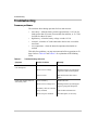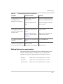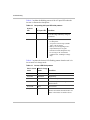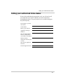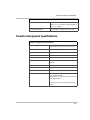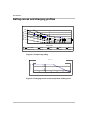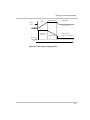
1
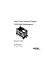
Heavy Duty Inverter/Charger
1000 Watt Weatherproof
Owner’s Guide
Model RM1012
For Volvo Trucks
About Xantrex
Xantrex Technology develops, manufactures, and markets advanced power electronic products. The
company’s products convert raw electrical power from any source into high-quality power required by
electronic and electrical equipment.
Trademarks
Xantrex HD is a trademark of Xantrex International. Xantrex is a registered trademark of
Xantrex International.
© 2001 Xantrex International. All rights reserved.
Notice of Copyright
Xantrex™ Heavy Duty Inverter/Charger Owner’s Guide © November 2001 Xantrex International.
Disclaimer
UNLESS SPECIFICALLY AGREED TO IN WRITING, XANTREX TECHNOLOGY INC.
(“XANTREX”):
(a) MAKES NO WARRANTY AS TO THE ACCURACY, SUFFICIENCY OR SUITABILITY OF ANY
TECHNICAL OR OTHER INFORMATION PROVIDED IN ITS MANUALS OR OTHER DOCUMENTATION.
(b) ASSUMES NO RESPONSIBILITY OR LIABILITY FOR LOSS OR DAMAGE, WHETHER DIRECT,
INDIRECT, CONSEQUENTIAL OR INCIDENTAL, WHICH MIGHT ARISE OUT OF THE USE OF SUCH
INFORMATION. THE USE OF ANY SUCH INFORMATION WILL BE ENTIRELY AT THE USER’S RISK.
Date and Revision
November 2001, Revision 2
Part number
445-0128-01-01 (Volvo)
Contact information
Volvo Trucks North America, Inc.
P.O. Box 26115 Greensboro, NC 27402
Volvo Trucks Canada, Inc.
6490 Vipond Drive, Mississauga, Ontario L5T 1W8
1-800-52-VOLVO (1-800-528-6586)
www.volvotrucks.com
Contents
Important Safety Information
General precautions - - - - - - - - - - - - - - - - - - - - - - - - - - - - - - - - - - - - - - - - - - - v
Precautions when working with batteries - - - - - - - - - - - - - - - - - - - - - - - - - - - - - v
Precautions for using appliances - - - - - - - - - - - - - - - - - - - - - - - - - - - - - - - - - - - vi
1
Introduction
Introduction to the Xantrex HD - - - - - - - - - - - - - - - - - - - - - - - - - - - - - - - - - -1–2
Operating features - - - - - - - - - - - - - - - - - - - - - - - - - - - - - - - - - - - - - - - - - - -1–4
2
Operation
Planning for AC loads- - - - - - - - - - - - - - - - - - - - - - - - - - - - - - - - - - - - - - - - -2–2
Type of loads - - - - - - - - - - - - - - - - - - - - - - - - - - - - - - - - - - - - - - - - - - - - -2–2
AC loads - - - - - - - - - - - - - - - - - - - - - - - - - - - - - - - - - - - - - - - - - - - - - -2–2
DC loads - - - - - - - - - - - - - - - - - - - - - - - - - - - - - - - - - - - - - - - - - - - - - -2–3
Problem loads - - - - - - - - - - - - - - - - - - - - - - - - - - - - - - - - - - - - - - - - - - -2–3
Ambient temperature - - - - - - - - - - - - - - - - - - - - - - - - - - - - - - - - - - - - - - - -2–3
Calculating size of an AC load - - - - - - - - - - - - - - - - - - - - - - - - - - - - - - - - -2–4
Driving the truck while operating AC and DC loads - - - - - - - - - - - - - - - - - - -2–7
Using the toggle switch - - - - - - - - - - - - - - - - - - - - - - - - - - - - - - - - - - - - - - - -2–9
Operating the Inverter/Charger - - - - - - - - - - - - - - - - - - - - - - - - - - - - - - - - - - 2–11
Turning the inverter on and running loads - - - - - - - - - - - - - - - - - - - - - - - - - 2–11
Running in extremes of hot or cold temperatures - - - - - - - - - - - - - - - - - - - - 2–11
Restarting after a shutdown- - - - - - - - - - - - - - - - - - - - - - - - - - - - - - - - - - - 2–11
Battery charging - - - - - - - - - - - - - - - - - - - - - - - - - - - - - - - - - - - - - - - - - - 2–12
Using shorepower - - - - - - - - - - - - - - - - - - - - - - - - - - - - - - - - - - - - - - - - - 2–12
Miscellaneous hints - - - - - - - - - - - - - - - - - - - - - - - - - - - - - - - - - - - - - - - - 2–12
iii
Contents
3
Maintenance
Checking terminals- - - - - - - - - - - - - - - - - - - - - - - - - - - - - - - - - - - - - - - - - - -3–2
Disconnecting and connecting Xantrex HD from the batteries - - - - - - - - - - - - - -3–3
Disconnecting - - - - - - - - - - - - - - - - - - - - - - - - - - - - - - - - - - - - - - - - - - - - -3–3
Connecting - - - - - - - - - - - - - - - - - - - - - - - - - - - - - - - - - - - - - - - - - - - - - - -3–3
Replacing the fuse - - - - - - - - - - - - - - - - - - - - - - - - - - - - - - - - - - - - - - - - - - -3–4
Removing and reconnecting AC cables - - - - - - - - - - - - - - - - - - - - - - - - - - - - -3–6
4
Troubleshooting
Troubleshooting- - - - - - - - - - - - - - - - - - - - - - - - - - - - - - - - - - - - - - - - - - - - -4–2
Common problems - - - - - - - - - - - - - - - - - - - - - - - - - - - - - - - - - - - - - - - - -4–2
Blinking lights on the remote switch- - - - - - - - - - - - - - - - - - - - - - - - - - - - - -4–3
Calling your authorized Volvo dealer - - - - - - - - - - - - - - - - - - - - - - - - - - - - - -4–5
A
Specifications
Physical specifications - - - - - - - - - - - - - - - - - - - - - - - - - - - - - - - - - - - - - - Inverter specifications- - - - - - - - - - - - - - - - - - - - - - - - - - - - - - - - - - - - - - - Charger specifications- - - - - - - - - - - - - - - - - - - - - - - - - - - - - - - - - - - - - - - Transfer and general specifications - - - - - - - - - - - - - - - - - - - - - - - - - - - - - - Rating curves and charging profiles - - - - - - - - - - - - - - - - - - - - - - - - - - - - - -
A–2
A–3
A–4
A–5
A–6
Index - - - - - - - - - - - - - - - - - - - - - - - - - - - - - - - - - - - - - - - - IX–1
iv
Important Safety Information
WARNING
Before using your Inverter/Charger, read and save these safety
instructions.
General precautions
1. Before using the inverter/charger, read all appropriate sections of
this guide and any cautionary markings on the inverter and the
batteries.
2. Use only a grounded AC extension cord when connecting to AC
input power (shorepower). Do not remove or attempt to defeat the
ground connection to any shorepower source in any way.
3. If possible, plug the inverter/charger into an AC source outlet that is
protected by a Ground Fault Circuit Interrupting (GFCI) device;
either a breaker or outlet.
4. Do not operate the inverter/charger if it has received a sharp blow,
been dropped, or otherwise damaged. If the unit is damaged, return
it to your authorized Volvo dealer.
5. Do not dismantle the inverter/charger; it contains no userserviceable parts. Attempting to service the unit yourself could
cause electrical shock or fire. Internal capacitors remain charged
after all power is disconnected.
6. To reduce the risk of electrical shock, turn off the inverter/charger
from the remote switch, then disconnect both AC (shorepower) and
DC (battery) power from the unit before working on any circuits
connected to it. Turning off the remote On/Off switch alone will not
reduce this risk.
Precautions when working with batteries
1. Follow all instructions published by the battery manufacturer and
the manufacturer of the equipment in which the battery is installed.
2. Make sure the area around the battery is well ventilated.
v
Important Safety Information
3. Never smoke or allow a spark or flame near the engine or battery.
4. Use caution to reduce the risk of dropping a metal tool on the
battery. It could spark or short circuit the battery or other electrical
parts and cause an explosion.
5. Remove metal items like rings, bracelets, and watches when
working with lead-acid batteries. These batteries produce a shortcircuit current high enough to weld a ring, other metal jewellery or
tools, thus causing severe burns.
6. If you need to remove a battery, always remove the negative
terminal from the battery first. Make sure all accessories are off so
you don’t cause an arc.
7. Before making the final connection to a battery, be sure the polarity
is correct; negative-to-negative, and positive-to-positive.
8. When you are making the final connection to a battery, you will see
a spark and hear a loud pop. This is normal.
Precautions for using appliances
Most battery-operated equipment uses a separate charger or transformer
that is plugged into an AC receptacle and produces a low voltage output.
If the label on the AC adapter or charger states that the adapter or
charger produces a low voltage AC or DC output (less than 30 volts),
the inverter/charger can power this charger or adapter safely.
Some rechargers for small nickel-cadmium batteries can be damaged if
connected to the inverter/charger. Do not use the following loads and
appliances:
•
•
vi
Small battery-operated appliances like flashlights, razors, and night
lights that can be plugged directly into an AC receptacle to
recharge.
Chargers for battery packs used in hand power tools. These types of
chargers display a warning label stating that dangerous voltages are
present at the battery terminals.
1
Introduction
Chapter 1, “Introduction” describes the main
performance and protection features of the
inverter/charger.
Introduction
Introduction to the Xantrex HD
Features
The Xantrex HD inverter/charger is a weatherproof, modified sine wave
inverter/charger designed to be mounted on main frame rail of the truck. It
is a sealed, dust and water resistant unit weighing approximately 30
pounds (13.6 kg). Figure 1-1 shows its main features.
Consult Appendix A, “Specifications” for more detailed information
about the unit.
⑦
}
①
②
③
④
Figure 1-1
1–2
Features of the inverter/charger
⑤
Introduction to the Xantrex HD
Location
Feature
Description
①
②
Positive terminal connecting to positive terminal of battery
③
④
⑤
Battery temperature sensor
}
Remote toggle switch connection. The connection must be
secure for the inverter to work
⑦
Negative terminal connecting to negative terminal of battery
Over-current protection fuse which blows in case of a fault
within the unit or if it is connected to the battery with reverse
polarity.
AC output to vehicle
AC input from shorepower
The inverter/charger is mounted on the main rail of the truck adjacent to
the battery compartment as shown in Figure 1-2.
Figure 1-2
Location of the inverter/charger
1–3
Introduction
Operating features
Inverter/charger
The inverter/charger operates as an inverter and as a charger depending
upon the operational conditions. When the unit is inverting, it is said to be
in invert mode and is referred to as an inverter. When the unit is charging,
it is in charge mode and is referred to as a charger.
The unit can only operate in charge mode when external AC power
referred to as “shorepower” is connected.
Inverter
features
Xantrex HD offers the following inverter features:
•
•
•
•
1–4
Ability to run many of the same appliances that you use at home
You can operate TVs, VCRs, satellite receivers, computers, hair
dryers, and small power tools for example. You can also run multiple
loads up to 1000 watts in total.
Surge capability
Xantrex HD will manage loads up to 3000 watts for short periods of
time as long as the peak current is less than 36 A peak.
Low voltage shutdown
The inverter shuts off when your batteries reach a predetermined
voltage set in the microprocessor to ensure you will always have
enough engine starting power. Low voltage shutdown also monitors
frequency and voltage, and protects against overload, short circuits
and over-temperature.
Automatic shutdown when the unit does not detect a load greater than
20 watts for 24 hours
This feature prevents the inverter from draining the batteries if it is
left on without a load.
Operating features
Charger
features
Xantrex HD offers the following charger features:
•
•
•
50 amp charging, when shorepower is connected, to ensure your truck
batteries are always charged
Automatic transfer to invert mode
When your truck’s AC shorepower cord is disconnected, the unit
automatically switches to invert mode. When AC shorepower is
available again, the inverter automatically switches to charging/passthrough mode.
Load management capability which temporarily reduces charging
current to the batteries when a large AC load is applied to the inverter
output. This capability helps reduce the chance of tripping the
shorepower breaker.
1–5
1–6
2
Operation
Chapter 2, “Operation” explains how to calculate
the size of the loads you can run from the
Xantrex HD Inverter/Charger. It also provides
guidelines to help you run loads safely and
efficiently.
Operation
Planning for AC loads
AC load
AC load refers to an AC product you want to operate from the
inverter/charger. Loads include most products that you can plug into a
standard 120 volt household electrical outlet.
Variables
affecting AC
loads
The Xantrex HD inverter/charger inverter can power a wide range of
loads. The size of the load and the length of time you can operate it
depends on variables such as
•
•
•
type of load
ambient temperature
size, state of charge, temperature, and condition of batteries.
The larger your battery capacity and the higher the state of charge, the
longer the inverter/charger can run your AC loads. Battery capacity is
reduced as battery temperature lowers.
Type of loads
AC loads
The way in which an AC load draws power may determine how
effectively it can be powered from the inverter/charger.
Resistive loads
Toasters, coffee pots and incandescent lights are examples of loads which
do not need a high start-up current to start running. They use a resistive
heater element to generate heat or light. They are the simplest and most
efficient for an inverter/charger to run. Large resistive loads, such as
electric stoves and water heaters, are impractical since their high current
demands quickly drain the batteries.
Inductive loads
TVs, VCRs, stereos, computers, and electric motors (power tools,
vacuum cleaners, for example) are examples of AC loads which surge on
start up, that is, they require a high startup current compared to a resistive
load such as toasters or coffee pots. These loads are known as inductive or
electronic loads. Depending upon the size of the motor, it can take as
much as six times its running current to start it than it does to keep it
running once it has started. This surge can sometimes exceed the
inverter/charger’s maximum output rating and the inverter will shut
down.
2–2
Planning for AC loads
DC loads
DC loads are those that run off the 12 V electrical system on the truck. A
few examples of DC loads are:
•
•
•
•
marker lights, headlights, cab lighting, other lights using DC power
DC refrigerators
CBs
factory-installed radios or sound systems
DC loads and the inverter/charger both rely on the batteries for power.
Many DC loads running at one time will shorten the operating times of
AC loads.
Problem loads
These are loads you should not operate from inverter/charger because
they may be damaged or may not operate properly:
•
•
•
•
dimmer switches
some small rechargeable hand power tool chargers
small battery-operated appliances such as flashlights, razors, night
lights
variable speed motors
Ambient temperature
Ambient
temperature
The ambient temperature, that is, the air temperature around the
inverter/charger will affect its output power.
The air temperature around the inverter may be much hotter than away
from the vehicle. If your truck is standing on hot pavement, the
temperature may be quite high near the inverter.
Temperature
and power
Generally, the output power decreases as the temperature increases. For
example, at 77 °F (25 °C) the unit delivers 1000 watts for as long as you
have sufficient battery power. At 104 °F (40 °C) it delivers 1000 watts for
up to 10 minutes before shutting down or 750 watts continuous, or 2000
watts for 2 1/2 minutes.
Figure 2-1 shows the relationship between ambient temperature and the
length of time the unit will supply an output power level. Choose the
curve with temperature range most closely approximating that of the
inverter/charger location, then look for the time in minutes. The
2–3
Operation
intersection of the time and temperature will indicate approximately the
output power of the unit. For example, between – 40 °F (– 40 °C) and
77 °F (25 °C), you will get 3000 watts for approximately two minutes or
2500 watts for 3 minutes.
Output Power (VA)
3000
2500
2000
1500
1000
500
0
2
1
3
4
5
6
7 8 9 10
100
Time (minutes)
-40 to 25C
– 40 to 77 F
Figure 2-1
40C
104 F
55C
131 F
70C
158 F
85C
185 F
Output power versus time and temperature
Calculating size of an AC load
Operating time
To determine how long you can run your appliances:
1. List all the AC loads you think you will use and determine their
power requirement. You can usually find this information on a label
near the power cord on the appliance.
2. Look in Table 2-1 to find its operating time or the operating time of a
similarly sized appliance. The operating times shown in the table are
the maximum time the appliance will operate. The unit will shut
down after that time so the battery is not drained past a safe level.
3. To find the running time for several appliances running
simultaneously add the total watts of the appliances and look for an
appliance with similar power requirement in Table 2-1.
Battery
condition
2–4
The information in Table 2-1 assumes:
•
•
there is a properly maintained 400 amp-hour battery bank
the batteries have not been damaged by deep discharge and are
relatively new
Planning for AC loads
Factors
affecting load
Consider these factors when you are calculating loads:
•
•
•
•
Loads that exceed 1000 watts may be run for a short time (less than
five minutes)
Loads which run continuously, (reading light, TV, computer) should
not exceed more than 1000 watts in total
Poor battery condition, low battery capacity, low battery temperature,
and high ambient temperature will shorten the operating times listed
in the table
The presence of DC loads will reduce the operating times
2–5
Typical operating time with fully-charged 400 amp-hour batteries †
Appliance
Watts
Electric shaver
15
15
25
40
75
100
100
100
180
Minutes
Hours
10 20 30 40 50 1
Table fan
Video game
Reading Lamp
Notebook computer
Computer printer
Hand-held vacuum cleaner
19 in TV/VCR combo
3 cu. ft. refrigerator *
Electric blanket
Electric buffer
Electric drill 1/2”
Halogen work light
Coffee maker
Toaster
Microwave oven
Hair dryer
Operation
2–6
Table 2-1
2
3
4
5
6
9
200
400
500
750
800
1000
1200
1500
* Average
The inverter/charger shuts down after 24 hours if it does not detect a load (or loads less than 20 W).
†
Based on four minute operation timeout and shutdown at 11.8 V for loads more than 150 W
and 12.3 V timeout and shutdown for loads less than 150 W at 77 °F (25 °C).
18 24
Planning for AC loads
Driving the truck while operating AC and DC loads
Recharging
Driving your truck does not guarantee that the battery is being fully
recharged by the alternator if you are running a combination of large AC
and DC loads.
The alternator must provide more power than the combined DC and AC
loads draw for your battery to fully recharge.
Example
This example shows what happens if the alternator is overloaded.
92 A
1110 W (DC)
AC Loads
(1000 W)
Xantrex HD
Alternator
(130 A)
12 Volt Battery
Driver Installed
Loads
38 A
Factory Installed
Loads
DC Loads
Figure 2-2
AC and DC loads powered by the alternator
The alternator is charging at 130 amps while the truck is being driven at
highway speeds and there is a 1000 W (AC) load.
2–7
Operation
The efficiency of the inverter/charger is approximately 90%, which means it
is drawing about 1100 W (DC) from the battery or 92 amps. This leaves
38 amps for all DC loads. If the DC loads require more than 38 amps, the
battery will actually discharge even though the alternator is running.
Indication
If the alternator is overloaded the:
•
Solutions
Comment
battery voltage gauge on the dashboard begins dropping from
approximately 14 V towards 12 V
• inverter LED signals a low battery with a slow blink
• inverter shuts down at 11.8 V and AC loads will stop operating
• battery voltage gauge will climb again as the alternator now has enough
power to charge the battery
You can reduce the AC or DC load on the battery or, for continuous
operation of large AC and DC loads you can consider installing a larger
alternator.
Small alternator overloads may not be immediately noticeable and can take
several hours to discharge the batteries. Large overloads will discharge the
battery in a shorter time.
At low engine RPMs the alternator current will drop significantly causing
alternator overload to occur even with reduced AC and DC loads.
2–8
Using the toggle switch
Using the toggle switch
Location
The inverter/charger is controlled from the remote toggle switch on the
control panel in the cabin as shown in Figure 2-3.
Toggle switch
Figure 2-3
Switch
settings
Remote switch
The switch is used to disable the inverter. The charger is always on as long
as shorepower is connected.
If the switch is …
The inverter is …
On
Providing AC to the vehicle when there is no
shorepower and the battery voltage is acceptable.
Off
Providing pass-through AC to the vehicle only if
there is shorepower. The inverter is disabled and
will not provide AC power in the absence of
shorepower.
2–9
Operation
Switch LEDs
The LEDs provide information about the operating state of the
inverter/charger. Under normal operating conditions the lights will behave
like this:
AC LED:
Illuminated when there is shorepower.
Blinks slowly (once per second) when first connecting
to shorepower then lights steadily or it will continue to
blink if the AC voltage is not within range (100 V to
130 V).
Inverter LED: Illuminated when the unit is inverting and there is no
shorepower.
If the LED is blinking once every two seconds (very
slow blink), it means the unit has shut down to avoid
draining the batteries.
A fast-blinking Inverter LED light indicates a unit
fault. Refer to Chapter 4, “Troubleshooting” for more
information.
Note: Some switches may also have a center position. The center position also
enables the inverter.
Inverter disabled (off)
when switch pushed up
Inverter LED
AC LED
Inverter enabled (on)
when switch is pushed
down
Figure 2-4
2–10
Inverter/charger switch positions
Operating the Inverter/Charger
Operating the Inverter/Charger
This section provides guidelines for operating the Xantrex HD.
Turning the inverter on and running loads
To run loads:
• Put the switch in the On position by pressing down.
• Check that the inverter LED is illuminated and AC LED is off if you are
not connected to shorepower.
• Connect appliances one at a time to the inverter. Don’t connect too
many high-surge appliances at once. You may notice some appliances
halt or dim momentarily while another is starting up.
Running in extremes of hot or cold temperatures
Hot
In extremely hot conditions, the inverter may shut down sooner than it
would in normal or cold temperatures. The unit may be hotter than the
outside air temperature when parked on hot pavement, for example.
When the ambient temperature is high, reduce the number of loads.
Cold
In extreme cold temperatures, your batteries may have less stored energy. At
0 °F (– 18 °C) your battery has only half the standby power than it has at
77 °F (25 °C).
Restarting after a shutdown
If the appliances stop operating suddenly, it usually means that the battery
voltage is too low or you have drawn too much power for too long. Try
restarting the inverter by turning the switch off, then on again. If you are
running several loads, try disconnecting one or two of them. If it doesn’t
start right away, let the inverter rest a few minutes, then try again. The
batteries should be recharged as soon as possible. If it still refuses to power
your loads, start the vehicle to charge the batteries.
Note: Turning the switch off, then on again to restart after a shutdown
should only be considered a temporary measure. The batteries likely
need to be recharged.
2–11
Operation
Battery charging
When you are connected to shorepower, the AC LED is illuminated and the
unit is both passing power through to the appliances and charging the
batteries. To avoid low voltage problems, make sure your connection cord to
shorepower is not too long and that it is heavy enough to support the loads
you are running. A 14 or 12 gauge extension cord is recommended.
If the AC LED flashes slowly (about twice per second), this means the AC
voltage is out of range and your batteries are not charging.
Using shorepower
If you are running too many appliances you may either trip the 15 amp truck
breaker or the shorepower breaker. Reduce the load and reset the affected
breaker.
Note that the charger will automatically reduce battery charging if other AC
loads are connected. This helps to prevent nuisance tripping of the
shorepower breaker.
Miscellaneous hints
Automatic
shutdown
The inverter automatically turns off if it has not detected any AC loads for
24 hours or the loads are so small the inverter cannot detect them, such as an
alarm clock or very small television (less than 10-20 watts).
Output
power
Remember that the total output of the inverter/charger is 1000 watts and not
1000 watts per outlet (if there is more than one).
.
Note: The Xantrex HD does not provide any warning before it shuts
down. If you need to operate a critical AC load, be sure there are no
heavy loads connected and that the batteries have been recently charged.
Connect
delay to AC
power
If you are connected to shorepower, the AC LED should be on and the
inverter LED off. The AC LED may blink slowly when you first apply
shorepower because of a connect delay (about 30 seconds), but then will
illuminate steadily.
Load failure
If any loads fail to operate, or the inverter shuts down, refer to Chapter 4,
“Troubleshooting” for suggestions.
2–12
3
Maintenance
Chapter 3, “Maintenance” provides procedures for checking
the terminal connections on the inverter/charger,
disconnecting Xantrex HD from the batteries, changing the
overcurrent protection fuse, and removing or connecting the
AC input and output cables.
3–1
Maintenance
Checking terminals
To check that the battery cables are firmly connected, you will need to
remove the terminal caps.
To remove the terminal cap:
1. Using a flathead screwdriver as shown in Figure 3-1, place the blade
in the lip of the cap and push it gently against the cap until it lifts off.
2. To replace the cap, place it over the terminal and push down until it
snaps into place.
3
1
2
Figure 3-1
3–2
Lifting the terminal cap
Disconnecting and connecting Xantrex HD from the batteries
Disconnecting and connecting Xantrex HD from the
batteries
Before doing any work with your batteries or with the inverter/charger,
review “Important Safety Information” on page v.
Disconnecting
WARNING: Explosion or Fire
Make sure the battery compartment is well ventilated.
Flammable fumes are often present when working with
batteries.
To disconnect from the battery:
1. Disconnect the shorepower cable and turn the
inverter/charger off.
2. Remove the inverter/charger cables from the battery.
Disconnect the negative connection first at the inverter/charger
terminal and then disconnect the positive at the battery terminal.
3. If you are replacing batteries, make sure they are the same kind and
capacity as you are currently using.
4. Disconnect the ground wire if the unit must be removed from its
mounting bracket.
Connecting
To connect to the batteries:
1. Ensure shorepower is disconnected and the inverter/charger is off.
2. Connect the ground wire if it was previously removed
CAUTION: Reverse Polarity
Do not connect cables in reverse polarity. If you do, the fuse will
blow the fuse and the unit could be damaged.
3–3
Maintenance
WARNING: Explosion or Fire
Do not complete the next step if flammable fumes are
present. Explosion or fire may result. Thoroughly ventilate
the battery compartment before making this connection.
3. Connect the positive battery cable from the inverter/charger to the
positive terminal on the battery; then the negative to the negative with
the last connection made at the Xantrex HD terminal to prevent
sparks. You may hear an audible “pop” and see a spark when you
make the last connection.
4. Tighten to a torque of 14.5 ft-lbs (+/-10%).
5. Check that the inverter is operating by enabling it from the toggle
switch as explained in “Using the toggle switch” on page 2–9.
Replacing the fuse
WARNING: Correct fuse type
To reduce the risk of fire and electrical hazards, replace the fuse
with a fuse of the same type and rating.
Using the wrong fuse type can damage the unit and void your
warranty.
The inverter/charger over-current protection fuse, shown in Figure 1-1,
protects the unit from internal failure or reverse polarity when connecting
it to the battery. If it blows for any reason, replace it with only the fuse
types listed below.
• Littelfuse Mega® Fast Blow, 250 A, 32 V; part number 298250
• Bussmann® 250 A 48 V; part number AMG-250
To replace the fuse:
1. Lift the fuse cover off as shown in Figure 3-2.
2. Remove the spent fuse and install the new fuse.
Be sure to use a lock washer when replacing the nuts. Tighten to a
torque of 4-5.5 ft-lb (5.5-7.5 Nm).
3–4
Replacing the fuse
.
CAUTION: Do not overtighten fuse nuts!
3. Replace the fuse cover by placing it over the fuse and pressing down
until it snaps into place.
If the fuse blows a second time without being able to operate the unit,
do not change the fuse again. Call your authorized Volvo dealer.
3
1
2
Figure 3-2
Removing the fuse cover
3–5
Maintenance
Removing and reconnecting AC cables
To remove the AC cables:
➣ Grasp the knurled surface of the connector housing as shown in
Figure 3-3 and turn counter clockwise approximately one-half turn.
Gently pull the cable out by grasping the connector.
To reconnect:
➢ Insert the plug firmly. Turn the connector housing clockwise 1/2 turn
until you feel resistance, then another 1/8 turn until it locks into place.
Power to vehicle
Shorepower
Turn these counterclockwise
to remove
Figure 3-3
3–6
AC input and output cables
4
Troubleshooting
Chapter 4, “Troubleshooting” provides
information to help you identify common
problems which may occur. Read this chapter
before calling your authorized Volvo dealer. If
you cannot solve the problem, record the details
as suggested on page 4–5, then call your dealer.
Troubleshooting
Troubleshooting
Common problems
The unit shuts down during operation for four main reasons:
•
•
•
•
low battery—when the battery reaches approximately 11.8 Vdc (for
loads greater than 150 watts) for more than four minutes, or 12.3 Vdc
for loads less than 150 watts.
high battery—when the battery voltage exceeds 16 Vdc
overload—when the AC load connected to the inverter exceeds the
rated load
over temperature—when the internal temperature thresholds are
reached
This table lists problems you may encounter and offers suggestions to fix
them. Refer to Table 4-2 and Table 4-3 for explanation of the blinking
LEDs.
Table 4-1
Troubleshooting reference
Symptom
Possible Problem
Remedy
Loads will not start when there
is no shorepower
Inverter not turned on
Turn the inverter on
Batteries at low voltage
Recharge batteries by running the
engine or connect to shorepower
Inverter too hot
Wait until inverter has cooled
down
Load is too heavy
Reduce the load
Batteries at low voltage level
Recharge batteries by running the
engine or plug into shorepower
Loads stop running almost as
soon as they start
4–2
Bad battery cable or corroded
battery terminals
Check cable and connectors
Batteries in poor condition
Test and replace, if necessary
Troubleshooting
Table 4-1
Troubleshooting reference (Continued)
Symptom
Possible Problem
Remedy
Loads stop operating without
warning after they have been
running for awhile
Shorepower not connected
Too many appliances have
reduced battery voltage to
shutdown level
Reduce number of loads. Allow
inverter to cool and restart. Start
the truck to recharge the batteries.
Ambient temperature is too
high
Disconnect appliances and let the
unit cool down
Remote switch may be
disconnected at the unit (not
likely)
Check that the remote switch is
firmly connected
Fuse on the unit (shown in
Figure 1-1) may have blown
(not likely)
Replace fuse or return unit to an
authorized Volvo dealer
AC voltage at receptacles
reads low
Wrong type of volt meter being
used
Use a true RMS meter
In inverter mode, times to
shutdown are getting shorter
for the same kind of AC load
Bad battery cable or corroded
battery terminals
Batteries too old or damaged
Check cables and connectors
Inverter will not work even
after toggling switch and
batteries are charged and the
inverter is cold
Replace batteries
Blinking lights on the remote switch
This table describes the different sequences of blinking lights you may
encounter when the inverter is enabled (switch is on) or the unit is
charging (switch is off). Light sequences are described as follows:
L
Fast blink
Light is on for 1/4 second and off for 1/4 second
Slow blink
Light is on for 1/2 second and off for 1/2 second
Very slow blink
Light is on for one second and off for one second
4–3
Troubleshooting
Table 4-2 explains the blinking pattern of the AC input LED when the
inverter is connected to shorepower.
Table 4-2
Interpreting AC input LED blink patterns
Inverter
LED
AC input LED
Condition
Off
ON
Connected to shorepower within 100
to 130 Vac range and battery charger is
operational
Off
Very slow blink
•
•
•
•
Delay on transfer from the inverter
to shorepower
AC power is not in range (outside
100 to 130 Vac range)
Battery is not being charged. AC
output load may be too great
Extension cord to shorepower may
be too long or not of sufficient
conductor size, resulting in voltage
drop
Table 4-3 explains the inverter LED flashing pattern when the unit is in
invert mode or in charge mode.
Table 4-3
4–4
Inverter LED blink patterns
Unit in invert
mode
Unit in charge
mode
Condition
Slow blink
N/A
Low battery
Fast blink
Fast blink
High battery
Fast blink
Slow blink
Unit over temperature and has shut down
Fast blink
Slow blink
Ambient temperature too high and unit
has shut down
Slow blink
N/A
Over current
Very slow blink
N/A
Auto shutdown. Inverter has shut down
because no load has been detected in 24
hours or the load is too small to detect
Calling your authorized Volvo dealer
Calling your authorized Volvo dealer
If none of the troubleshooting suggestions work, you will need to call
your authorized Volvo dealer. If possible, note the circumstances
surrounding the failure. They may help the service technician diagnose
the problem quickly.
How long have you had
the inverter?
Serial number
Battery types and sizes
Appliances running at
shutdown
Were the LEDs flashing
and if so, what pattern
(slow blinks? fast blinks?)
Was the ambient
temperature extremely hot
or cold?
Were any DC appliances
affected?
Has this happened before?
4–5
4–6
A
Specifications
Appendix A “Specifications” contains the
Xantrex HD product specifications, which
include the inverter, charger, and transfer
specifications. It shows derating curves for
output surge, current versus temperature, and
pass-through current. It also illustrates the threestage charging profile used by the unit.
Note that all specifications are subject to change
without notice.
Specifications
Physical specifications
Physical specifications
A–2
Enclosure
Sealed; dust and water-resistant
Dimensions
Approximately. 8.5" (21.8 cm)H x 7”
(17.7 cm)W x 13.0"(33.0 cm)D, excluding DC
ground connector (similar to Group 31 battery
dimensions)
Net weight
30 lbs. maximum without mounting brackets or
external cables
External finish
Base - Clear anodized aluminium.
Cover -Black polycarbonate/ABS plastic
Mounting Orientation
Upright only
Mounting method
Four M8x1.25 threaded holes accessible from
bottom only, one in each corner, and /or battery
hold-down bar over center top of cover.
Recommended torque: 5-6 ft-lb (7-8 Nm)
Battery cable
#2/0 AWG Minimum, maximum 6 feet long,
each way
Battery size
300 Ah acceptable; 400 Ah recommended
Inverter specifications
Inverter specifications
All inverter specifications are at nominal conditions; 77 °F (25 °C,)
1000 W resistive load, 12 Vdc inverting, 120 Vac, unless otherwise
specified.
Inverter specifications
Output wave form
Modified sine wave
Output power continuous
1000 VA continuous at 77 °F (25 °C)
Surge rating
3000 VA for 2 min at –40 °F to 77 °F (–40 °C to
25 °C)
See Figure A-1 for output at different
temperatures.
Operating voltage range
10.5 Vdc–16.0 Vdc
Input DC voltage rating
12 Vdc
Output voltage
120 Vac RMS
Output voltage regulation
108 to 125 Vac under steady state 0 to 1000 W
load with 11.8 to 14.5 Vdc input at 25 °C
108 to 132 Vac up to 1000 W, 10.5to 16 Vdc
input at – 40 to 185 °F (–40 °C –85 °C)
Output frequency
60.0 ± 0.1 Hz – 40 °F to 185 °F (– 40 °C to
85 °C ambient temperature)
Power factor allowed
All (0 to 1, leading or lagging)
Peak efficiency
Greater than 93% at 12.6 Vdc input at 77 °F
(25 °C)
Idle power consumption
Less than15 W (inverting with 120 Vac output
and no load)
Auto-shutdown mode
Inverter output is less than 15 ±5 W and battery
is less than 13 Vdc for 24 hours
A–3
Specifications
Inverter specifications (continued)
Shutdowns and Restarts
DC low voltage shutdown
1.
2.
Battery voltage drops below 11.8 ±0.15
Vdc at heavy loads (more than 150 W) or
12.3 Vdc at light loads (less than 150 W)
for more than 4 min and 10 sec (± 30 s)
Battery voltage is below 10.5 ± 0.2 Vdc for
3 seconds
DC low voltage restart
12.5 ± 0.15 Vdc
DC high voltage shutdown
16.0 ± 0.2 Vdc
DC high voltage restart
Less than 16.0 Vdc, same as DC high voltage
shutdown; there is no hysteresis
Charger specifications
All charging specifications are at nominal conditions, 77 °F (25 °C), 14.0
Vdc at 50 A charging, 120 Vac, 60 Hz unless otherwise specified.
Charger specifications
Charging method
•
•
•
A–4
Three-stage charging with battery
temperature compensation.
See Figure A-3.
Algorithm for generic flooded batteries
only
No equalization mode
AC input voltage
100–130 Vac
AC input frequency
54–66 Hz
Minimum battery voltage
8 Vdc
The charger does not operate below this level
Maximum charger input current
13.0 Aac rms
Maximum charge rate
50 ± 5 Adc. See Figure A-2
Charger efficiency
Greater than 80%
Absorption charge voltage
14.3 ± 0.3 Vdc at 77 °F (25 °C)
Float charge voltage
13.4 ± 0.3 Vdc at 77 °F (25 °C)
Transfer and general specifications
Charger specifications (continued)
Temperature compensation
– 0.023 Vdc/ °C from -2 °C to 85 °C.
Below -2 °C, the charger voltage defaults to
the – 2 °C voltage
Overvoltage shutdown
Greater than or equal to 15.3 ± 0.3 Vdc
Transfer and general specifications
Transfer and general specifications
AC input/bypass current
20 Aac maximum continuous at 77 °F (25 °C)
Derates after 30 °C to 5 Aac at 185 °F (85 °C)
Transfer speed
10–40 ms typical
AC low voltage transfer
90 ±5 Vac
AC low voltage restart
95 ±5 Vac, 30 second delay
AC high voltage transfer
None
Standby/off consumption
< 0.7 at 12.5 Vdc with charger and inverter
both off
Operating temperature range
– 40 °F to +185 °F (– 40 °C to +85 °C)
Storage temperature range
– 40 °F to +185 °F (– 40 °C to +85 °C)
Altitude limit
15 000 feet (5000 metres)
AC neutral to ground bonding
Invert mode: AC output neutral is connected
to AC ground (chassis)
Charge mode: AC output neutral is connected
to AC input neutral
AC input neutral is always isolated form AC
ground
A–5
Specifications
Rating curves and charging profiles
Output Power (VA)
3000
2500
2000
1500
1000
500
0
2
1
4
3
6
5
7 8 9 10
100
Time (minutes)
-40 to 25C
40C
55C
70C
85C
– 40 to 77 F
104 F
131 F
158 F
185 F
Figure A-1 Output surge rating
R M 1 0 1 2
M a x . c h a r g e r c u r re n t v s
T e m p e r a tu re
Charger current (Amps)
6 0
5 0
4 0
3 0
2 0
1 0
0
-4 0
-2 0
0
2 0
4 0
A m b ie n t te m p e r a tu r e
6 0
8 0
(C )
Figure A-2 Charging current versus temperature derating curve
A–6
Rating curves and charging profiles
Bulk
Charging
Started
Absorption Charge
Float Charge
Bulk Volts Setting
Float Volts Setting
DC Voltage
Constant Current
@ Maximum
Charge Rate
Reduced
Reduced
CurrentVoltage
and Voltage
Constant Voltage
Load current on demand
DC Current
Time
Figure A-3 Three-stage charging profile
A–7
A–8
Index
A
AC cables, removing or connecting 3–6
AC load
calculating size 2–4
definition 2–2
factors affecting 2–2
types of 2–2
AC power, connect delay 2–12
alternator, effects of overloading 2–7
ambient temperature
effect on operation 2–2, 2–11
effect on output power 2–3
appliances
see AC load
battery-operated vi
authorized dealer, calling 4–5
auto shutdown feature 1–4
automatic shutdown 2–12
automatic transfer between AC and DC
1–5
B
batteries
charging with Xantrex HD 2–12
nickel-cadmium vi
precautions for working with v
battery cables, disconnecting 3–3
battery condition, effect on AC loads 2–5
battery operated appliances see problem
loads
battery packs vi
breaker switch
resetting 2–12
C
charger features 1–5
charger specifications A–4
charging current 1–5
common problems, suggestions for 4–2
connect delay to AC power 2–12
current vs temperature derating curve A–
6
D
DC loads
effect on alternator 2–7
effect on operating times of AC loads
2–3
derating curves, current vs temperature
A–6
dimmer switch see problem loads
disconnecting Xantrex HD from
batteries 3–3
E
explosive fumes 3–4
extension cord, length of 4–4
Index
F
P
flashlights see problem loads
fuse, over-current protection 1–3
fuse, replacing 3–4
physical specifications A–2
problem loads 2–3
H
high battery shutdown 4–2
I
inductive load see AC loads
inverter features 1–4
inverter specifications A–3
L
LEDs
blinking patterns 4–2
load management capability 1–5
loads see AC load 2–2
loads, effect of large loads on alternator 2–7
low AC, causes of 4–4
low battery shutdown 4–2
low voltage shutdown 1–4
M
maintenance
checking terminal connections 3–2
disconnecting battery cables 3–3
replacing the fuse 3–4
N
nickel-cadmium batteries vi
O
operating time of AC loads (table) 2–6
over temperature shutdown 4–2
overload shutdown 4–2
IX–2
R
rating curves
output surge rating A–5
razors see problem loads
rechargeable tools see problem loads
remote switch
blinking lights on the 4–3
resistive load see AC load, type of
resistive loads, examples of 2–2
restarting after shutdown 2–11
S
safety information v
safety monitoring feature 1–4
servicing, no user-serviceable parts v
shorepower, definition 1–4
shutdown
automatic 2–12
restarting after 2–11
size of AC load, calculating 2–4
surge capability 1–4
surge loads, examples of 2–2
Index
T
temperature see ambient temperature
temperature and power, relationship of 2–3
temperature and time derating curve (figure) 2–4
terminals caps, removing 3–2
three-stage charging profile A–6
time, running time of AC loads 2–4
toggle switch
purpose 2–9
torques for fuse replacement 3–4
transfer specifications A–5
troubleshooting reference 4–2
U
using Xantrex HD, guidelines for 2–11
V
variable speed motor see problem loads
X
Xantrex HD
as a charger 1–4
as an inverter 1–4
common problems 4–2
condition for shutdown 4–2
derating curves for A–5
disconnecting from batteries 3–3
location in truck 1–3
main features 1–2
maintaining 3–1
turning on 2–11
Xantrex HD features (figure) 1–2
IX–3