1
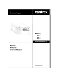
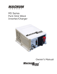
RC6
User’s and Installation Guide
Xantrex
RC6 Remote
On/Off Switch and Monitor
RC6 REMOTE ON/OFF SWITCH AND MONITOR
1
XANTREX TECHNOLOGY, INC
RC6 User’s and Installation Guide
Notice of Copyright
Xantrex RC6 Remote On/Off Switch and Monitor © October 2002 Xantrex International. All rights reserved.
Xantrex is a registered trademark of Xantrex International.
Disclaimer
UNLESS SPECIFICALLY AGREED TO IN WRITING, XANTREX TECHNOLOGY INC. (“XANTREX”)
(a)
MAKES NO WARRANTY AS TO THE ACCURACY, SUFFICIENCY OR SUITABILITY OF ANY
TECHNICAL OR OTHER INFORMATION PROVIDED IN ITS MANUALS OR OTHER DOCUMENTATION.
(b)
ASSUMES NO RESPONSIBILITY OR LIABILITY FOR LOSS OR DAMAGE, WHETHER DIRECT,
INDIRECT, CONSEQUENTIAL OR INCIDENTAL, WHICH MIGHT ARISE OUT OF THE USE OF SUCH
INFORMATION. THE USE OF ANY SUCH INFORMATION WILL BE ENTIRELY AT THE USER’S RISK.
Date and Revision
October 2002, Revision 1
Part Number
975-0051-01-01
Contact Information
Web: www.xantrex.com
Email: [email protected]
Phone: 1 800 670 0707 (toll free) 1 604 422 2777 (direct)
Fax: 1 604 420 2145
2
Table of Contents
Using the RC6 Remote On/Off and Inverter/Charger
Monitor ............................................................................................. 5
Reading the RC6 Remote Control.................................................................... 5
Power On/Off Switch and LED Indicator................................................................................ 6
Battery Voltage Bar Graph..................................................................................................... 6
Amps DC Bar Graph.............................................................................................................. 7
Error Conditions ..................................................................................................................... 7
Bulk Charge and Float Charge Lights.................................................................................... 8
Installation ..................................................................................... 10
Installation Procedure..................................................................................... 10
Warranty......................................................................................... 11
Disclaimer....................................................................................................... 13
Product ................................................................................................................................ 13
Exclusions............................................................................................................................ 13
Warning: Limitations On Use............................................................................................... 13
Return Material Authorization Policy............................................................... 14
Return Procedure ........................................................................................... 14
3
4
1
Section
Using the RC6 Remote On/Off and
Inverter/Charger Monitor
This section of the guide is designed to help the user interpret and operate
the RC6 remote when used with Xantrex RV Series Inverter/Chargers.
M
ost of the time the remote control will only be used to turn the inverter on
and off. However, should you wish, a multitude of information is available
about the state of the inverter/charger and battery system. Without a
remote control, the inverter will work just fine but most of the information the RC6
can show won’t be accessible to you. In this case, the indicator light and legend on the
front of the inverter will be your guide to what the inverter is doing.
Let’s look at some of the features of the Xantrex RC6 Remote Control.
Reading the RC6 Remote Control
The RC6 remote control is capable of turning the inverter on and off, as well as
showing the following:
• Battery Bank Voltage
• Current flowing into or out of the battery bank during charging or
inverting
• Error conditions the inverter may encounter (High Battery, Over
Temperature, Over Load, and Low Battery conditions)
• The charge state the inverter is currently in (Bulk Charge, Absorption, or
Float Charge)
• Whether the inverter is on or off
The following picture shows the front of the RC6. Notice the two bar graph scales
that run vertically. The left scale displays the voltage of the battery bank while the right
scale displays the DC (direct current) amperage flowing into (charging) or out of
5
!Voltage is
electrical
pressure. It is
equivalent to
(inverting) the battery bank. The lower portion of the Amps DC scale also
displays the four Error conditions. In the upper right portion of the RC6 are
two lights marked Bulk Charge and Float Charge. These lights indicate
the stage the battery charger is in. When the inverter is inverting, they are
not lit.
Battery current
(into or out of battery bank)
water pressure in
a hose.
Charge
lights
!Current or
Battery
voltage
Amps is the
volume of
electrical flow,
just like gallons
per hour through
Error legend
a garden hose.
On/Off button
Let’s take a more detailed look at each of the items pointed out in the picture above.
Power On/Off Switch and LED Indicator
The power on/off switch on the lower front right of the remote is a momentary type
switch and alternately turns the inverter on or off when pressed. The green light in the
middle of it will be lit steadily when the inverter is working, and if the inverter is in the
load search sense mode it will blink on and off rapidly. In charger mode the light will
blink slow green.
Battery Voltage Bar Graph
This bar graph contains a light that will move up and down the bar as the battery
voltage changes. The corresponding battery voltage is read to the left of the light. Red
lights mean out of tolerance, yellow lights marginally within tolerances, and green lights
show that everything is in a normal operating range. It is perfectly normal for battery
voltage to drop a bit when operating heavy loads. The inverter constantly monitors the
battery bank and will not allow it to be over discharged or over charged.
Note: A completely dead battery will read about 11.6 volts or less in an
“at rest” condition. “At rest” means the battery has been sitting dormant
for several hours with no load on it, and is not being recharged. When
the battery drops below a certain pre-set point, the inverter will shut
down, and if AC power is available to the inverter, it will recharge the
batteries.
6
Amps DC Bar Graph
The Amps DC bar graph functions just like the voltage bar graph, except now you
have a choice of two scales to read from. This meter tells you the volume of electricity
that is being taken out of or put back into the battery. If the unit is in inverter mode, as
indicated by an absence of Bulk or Float charge lights on the RC6, then read the scale
on the left side of the Amps DC meter. If the unit is in charger mode then the scale on
the right will indicate the volume of electricity in amps that is being put back into the
battery. All the lights on the Amps DC scale are red in color, so don’t be alarmed
when you see red lights.
Error Conditions
The RV and Truck series inverters are very well protected against a multitude of
potentially bad situations, and in normal usage it will be rare to see any error other than
possibly an occasional low battery condition (if you have small batteries or high usage).
If the inverter/charger encounters a situation it can’t handle then it will shut down and
protect itself, the battery bank, and your appliances. The following four situations are
monitored, protected against, and displayed on the RC6:
• High Battery - The battery voltage has risen above 15.0 volts DC
and the inverter will shut down until acceptable battery voltage has
been restored.
• Over Temperature - The internal temperature of the inverter has
risen above acceptable limits. The inverter will shut down until it
has cooled off enough to operate properly. This error may be
caused by loads too great for the inverter to operate continuously,
or it may be caused by lack of ventilation to the inverter. During
this type of error you should attempt to reduce the number of
electrical loads that you are operating, this will avoid a repeat overtemp shutdown if the cause was too many loads for the ambient
conditions.
7
"Error
conditions
indicated on the
RC6 may also be
viewed on the
front panel of
the inverter
itself.
"During an
overload condition
help the inverter
out by reducing the
Note: If your inverter routinely shuts down due to an overtemperature condition, then call your installer and describe the
problem. Routine over-temp shutdowns are indicative of a larger
problem, most likely poor ventilation in the inverter
compartment.
number of
electrical loads it
must run.
"When a low
battery condition
occurs, provide the
inverter/charger
with AC power by
starting the
generator or
plugging in to
shorepower. It will
then charge the
batteries.
• Over Load - Too much electrical load is present for the inverter to
power it. This would be like you trying to pick up 500 pounds
when 150 pounds is your limit. The inverter will shut down until
the amount of load has been reduced to a level it can handle. You
simply need to turn a few electrical appliances off until the inverter
can handle the loads that are present. In a properly designed system
this error is infrequent.
• Low Battery - The battery bank voltage has dropped to a level too
low to sustain full AC power output. To avoid damage to the
battery bank and AC loads due to low voltage “brown out”
conditions, the inverter will shut down. If an AC source is then
applied to the inverter (start the generator or plug into
shorepower), the inverter will go into charge mode and recharge
the batteries. The AC loads will then resume operation from the
pass through power, thus running from the external AC source.
The bottom four lights of the Amps DC meter show the error condition represented
by the adjacent Error box legend. During an error condition the appropriate error
light will flash. The inverter will attempt to automatically restart itself every few
seconds until the condition is remedied.
Bulk Charge and Float Charge Lights
Any time the inverter/charger has an alternating current source present it will use a
portion of that power to charge the battery bank—this is regardless of the position of
the on/off switch on the inverter or remote control.
In order to allow you to monitor the inverter’s charging cycle, two lights—Bulk
Charge and Float Charge— have been placed in the upper right corner of the RC6.
Xantrex chargers use a three-stage charging process which consists of three distinct
phases:
1.
Bulk Charge Stage
2.
Absorption Charge Stage, and
3.
Float or Maintenance Charge Stage
8
The purpose behind the three-stage charge process is to provide complete
recharging of the batteries without damage due to overcharging at too high a
current or voltage.
"The float
The bulk charging stage provides the battery with controlled constant current
charging and is the first step in the process. When the charger is in this stage the
Bulk Charge light on the RC6 will remain on solid.
During the Absorption Charge stage the Bulk Charge light will blink slowly.
This stage “tops off” the battery.
The float or maintenance charge stage trickle charges the battery while keeping it in
fully charged ready to go state. This stage is indicated on the RC6 by the Float Charge
light slowly flashing.
During the charge process the battery voltage and current being fed into the battery
may be monitored on the RC6 voltage and amp meters as discussed previously.
9
charge light
means the
battery is fully
charged and
ready for use.
2
Section
Installation
This section describes the basic installation of the Xantrex RC6
Remote On/Off Switch and Monitor.
Y
ou can install the RC6 easily if you follow a few basic rules and guidelines.
• Mount the RC6 in a dry location away from moisture and high humidity.
• Clean with a soft cloth dampened with water (you can use a little dish
soap if needed).
• Use Xantrex connector cable for best results. This cable is tinned its
entire length for better corrosion resistance.
Installation Procedure
You can mount the RC6 inside a cutout in a wall or panel. Using the faceplate as
a template, drill four 1/16-inch holes for mounting screws (not included). The
cutout for the RC6 should be 4-1/8 inches wide by 4-3/16 inches high by at
least 15/16 of an inch deep. Next plug the cable into the connector on the back
of the RC6, then to the inverter. It is never recommended to route any lowvoltage DC wiring (such as the RC6 cable) in the same conduit or bundle with
wiring that carries AC power. Induced current may cause false triggering, or, at
worst, failure of the electronic device to which the DC wiring is connected. The
last step is to set the RC6 in place and secure it with four mounting screws.
Plug the RC6’s cable into the port labeled remote on the inverter, turn the
inverter off and then on and the pair will be ready for service. That’s all there is
to it!
10
3
Section
Warranty
What does this warranty cover? This Limited Warranty is provided by
Xantrex Technology, Inc. ("Xantrex") and covers defects in workmanship and
materials in your Xantrex RC6 Remote Control. This warranty lasts for a
Warranty Period of 12 months from the date of purchase at point of sale to you,
the original end user customer.
This Limited Warranty is transferable to subsequent owners but only for the
unexpired portion of the Warranty Period.
What will Xantrex do? Xantrex will, at its option, repair or replace the
defective product free of charge, provided that you notify Xantrex of the
product defect within the Warranty Period, and provided that Xantrex through
inspection establishes the existence of such a defect and that it is covered by this
Limited Warranty.
Xantrex will, at its option, use new and/or reconditioned parts in performing
warranty repair and building replacement products. Xantrex reserves the right to
use parts or products of original or improved design in the repair or
replacement. If Xantrex repairs or replaces a product, its warranty continues for
the remaining portion of the original Warranty Period or 90 days from the date
of the return shipment to the customer, whichever is greater. All replaced
products and all parts removed from repaired products become the property of
Xantrex.
Xantrex covers both parts and labor necessary to repair the product, and return
shipment to the customer via a Xantrex-selected non-expedited surface freight
within the contiguous United States and Canada. Alaska and Hawaii are
excluded. Contact Xantrex Customer Service for details on freight policy for
return shipments outside of the contiguous United States and Canada.
11
How do you get service? If your product requires troubleshooting or
warranty service, contact your merchant. If you are unable to contact your
merchant, or the merchant is unable to provide service, contact Xantrex directly
at:
Phone: 1-800-670-0707 (toll-free in North America) 1-604-422-2777 (direct)
Fax: 1-604-420-2145
Email: [email protected]
Direct returns may be performed according to the Xantrex Return Material
Authorization Policy described in your product manual. For some products,
Xantrex maintains a network of regional Authorized Service Centers. Call
Xantrex or check our website to see if your product can be repaired at one of
these facilities.
In any warranty claim, dated proof of purchase must accompany the product
and the product must not have been disassembled or modified without prior
written authorization by Xantrex.
Proof of purchase may be in any one of the following forms:
• The dated purchase receipt from the original purchase of the
product at point of sale to the end user, or
• The dated dealer invoice or purchase receipt showing original
equipment manufacturer (OEM) status, or
• The dated invoice or purchase receipt showing the product
exchanged under warranty
What does this warranty not cover? This Limited Warranty does not cover
normal wear and tear of the product or costs related to the removal, installation,
or troubleshooting of the customer's electrical systems. This warranty does not
apply to and Xantrex will not be responsible for any defect in or damage to:
a) the product if it has been misused, neglected, improperly installed, physically
damaged or altered, either internally or externally, or damaged from
improper use or use in an unsuitable environment;
b) the product if it has been subjected to fire, water, generalized corrosion,
biological infestations, or input voltage that creates operating conditions
beyond the maximum or minimum limits listed in the Xantrex product
specifications including high input voltage from generators and lightning
strikes;
c) the product if repairs have been done to it other than by Xantrex or its
authorized service centers (hereafter "ASCs");
d) the product if it is used as a component part of a product expressly
warranted by another manufacturer;
e) the product if its original identification (trade-mark, serial number) markings
have been defaced, altered, or removed.
12
Disclaimer
Product
THIS LIMITED WARRANTY IS THE SOLE AND EXCLUSIVE
WARRANTY PROVIDED BY XANTREX IN CONNECTION WITH
YOUR XANTREX PRODUCT AND IS, WHERE PERMITTED BY LAW,
IN LIEU OF ALL OTHER WARRANTIES, CONDITIONS,
GUARANTEES, REPRESENTATIONS, OBLIGATIONS AND
LIABILITIES, EXPRESS OR IMPLIED, STATUTORY OR OTHERWISE
IN CONNECTION WITH THE PRODUCT, HOWEVER ARISING
(WHETHER BY CONTRACT, TORT, NEGLIGENCE, PRINCIPLES OF
MANUFACTURER'S LIABILITY, OPERATION OF LAW, CONDUCT,
STATEMENT OR OTHERWISE), INCLUDING WITHOUT
RESTRICTION ANY IMPLIED WARRANTY OR CONDITION OF
QUALITY, MERCHANTABILITY OR FITNESS FOR A PARTICULAR
PURPOSE. ANY IMPLIED WARRANTY OF MERCHANTABILITY OR
FITNESS FOR A PARTICULAR PURPOSE TO THE EXTENT
REQUIRED UNDER APPLICABLE LAW TO APPLY TO THE
PRODUCT SHALL BE LIMITED IN DURATION TO THE PERIOD
STIPULATED UNDER THIS LIMITED WARRANTY.
IN NO EVENT WILL XANTREX BE LIABLE FOR ANY SPECIAL,
DIRECT, INDIRECT, INCIDENTAL OR CONSEQUENTIAL
DAMAGES, LOSSES, COSTS OR EXPENSES HOWEVER ARISING
WHETHER IN CONTRACT OR TORT INCLUDING WITHOUT
RESTRICTION ANY ECONOMIC LOSSES OF ANY KIND, ANY LOSS
OR DAMAGE TO PROPERTY, ANY PERSONAL INJURY, ANY
DAMAGE OR INJURY ARISING FROM OR AS A RESULT OF MISUSE
OR ABUSE, OR THE INCORRECT INSTALLATION, INTEGRATION
OR OPERATION OF THE PRODUCT.
Exclusions
If this product is a consumer product, federal law does not allow an exclusion of
implied warranties. To the extent you are entitled to implied warranties under
federal law, to the extent permitted by applicable law they are limited to the
duration of this Limited Warranty. Some states and provinces do not allow
limitations or exclusions on implied warranties or on the duration of an implied
warranty or on the limitation or exclusion of incidental or consequential
damages, so the above limitation(s) or exclusion(s) may not apply to you. This
Limited Warranty gives you specific legal rights. You may have other rights
which may vary from state to state or province to province.
Warning: Limitations On Use
Please refer to your product user manual for limitations on uses of the product.
Specifically, please note that the RC6 is not intended for use in connection with
life support systems and Xantrex makes no warranty or representation in
connection with any use of the product for such purposes.
13
Return Material Authorization Policy
Before returning a product directly to Xantrex you must obtain a Return
Material Authorization (RMA) number and the correct factory "Ship To"
address. Products must also be shipped prepaid. Product shipments will be
refused and returned at your expense if they are unauthorized, returned without
an RMA number clearly marked on the outside of the shipping box, if they are
shipped collect, or if they are shipped to the wrong location.
When you contact Xantrex to obtain service, please have your instruction
manual ready for reference and be prepared to supply:
1. The serial number of your product
2. Information about the installation and use of the unit
3. Information about the failure and/or reason for the return
4. A copy of your dated proof of purchase
Return Procedure
1.
Package the unit safely, preferably using the original box and
packing materials. Please ensure that your product is shipped fully
insured in the original packaging or equivalent. This warranty will
not apply where the product is damaged due to improper packaging.
2.
Include the following:
• The RMA number supplied by Xantrex Technology Inc
clearly marked on the outside of the box.
• A return address where the unit can be shipped. Post office
boxes are not acceptable.
• A contact telephone number where you can be reached
during work hours
• A brief description of the problem
3.
Ship the unit prepaid to the address provided by your Xantrex
customer service representative.
If you are returning a product from outside of the USA or Canada
In addition to the above, you MUST include return freight funds and are fully
responsible for all documents, duties, tariffs, and deposits.
If you are returning a product to a Xantrex Authorized Service Center
(ASC) A Xantrex return material authorization (RMA) number is not required.
However, you must contact the ASC prior to returning the product or
presenting the unit to verify any return procedures that may apply to that
particular facility.
14
Xantrex Technology Inc.
Toll free 1 800 670 0707
Direct 1 604 422 2777
Fax 1 604 420 2145
[email protected]
www.xantrex.com
975-0051-01-01 Rev. 1
Printed in the U.S.A.