1
MZ3761K-DFI
872515G
37HP KAW DFI W/61” SIDE DISCHARGE
(S/N 000050 AND ABOVE)
MZ3772K-DFI
872516G
37HP KAW DFI W/72” SIDE DISCHARGE
REV B 12-2010
MAN0868
(S/N 000050 AND ABOVE)
RF4166229
Includes Maintenance
Instructions
OPERATOR’S MANUAL
MOW’N MACHINE
CALIFORNIA
WARNING
Proposition 65 Warning
Diesel engine exhaust and some of
its constituents are known to the State
of California to cause cancer, birth
defects and other reproductive harm.
The engine exhaust from this product
contains chemicals known to the State
of California to cause cancer, birth
defects or other reproductive harm.
Californie Proposition 65 Avertissement
Les échappements des moteurs diesel et certains
de leurs composés sont reconnus par l’Etat de
Californie pour être cancérigènes, provoquer
des défauts congénitaux et d’autres dangers en
matière de reproduction.
AVERTISSEMENT
L’émission du moteur de ce matériel contient des produits chimiques que l’Etat de
Californie considère être cancérigènes,
provoquer des défauts congénitaux et
d’autres dangers en matière de reproduction.
California Advertencia
de la Proposicion 65
ADVERTENCIA
El estado de California hace saber que
los gases de escape de los motores diesel
y algunos de sus componentes producen
cáncer, defectos de nacimiento y otros daños en el proceso de reproducción humana.
El estado de California hace saber que los
gases de escape de este producto contienen
productos quÍmicos que producen cáncer,
defectos de nacimiento y otros daños en
el proceso de reproducción humana.
CALIFORNIA
Proposition 65 Warning
Battery posts, terminals, wiring
insulation, and related accessories
contain lead and lead compounds,
chemicals known to the State of
California to cause cancer and birth
defects or other reproductive harm.
WASH HANDS AFTER HANDLING.
WOODS
IMPORTANT MESSAGE
TO THE DEALER:
Assembly and proper installation of this product is the responsibility of the Woods® dealer. Read manual
instructions and safety rules. Make sure all items on the Dealer’s Pre-Delivery and Delivery Check Lists in
the Set-Up instructions are completed before releasing equipment to the owner.
The dealer must complete the Product Registration online at the Woods Dealer Website or complete the
mail-in form included with the Operator’s Manual. If using the mail-in form, the dealer is to return the prepaid
postage portion to Woods, give one copy to the customer, and retain one copy. Failure to register the product
does not diminish customer’s warranty rights.
TO THE OWNER:
Read the Operator’s Manual before operating your Woods equipment. The information presented will prepare
you to do a better and safer job. Keep the manual handy for ready reference. Require all operators to read
the Operator’s Manual carefully and become acquainted with all adjustment and operating procedures before
attempting to operate the equipment. Replacement manuals can be obtained from your dealer. To locate
your nearest dealer, check the Dealer Locator at www.WoodsEquipment.com, or in the United States and
Canada call 1-800-319-6637.
The equipment you have purchased has been carefully engineered and manufactured to provide dependable
and satisfactory use. Like all mechanical products, it will require cleaning and upkeep. Lubricate the unit as
specified. Observe all safety information in this manual and safety decals on the equipment.
For service, your authorized Woods dealer has trained mechanics, genuine Woods service parts, and the
necessary tools and equipment to handle all your needs.
Use only genuine Woods service parts. Substitute parts will void the warranty and may not meet standards
required for safe and satisfactory operation. Record the model number and serial number of your equipment
in the spaces provided:
Model: _______________________________ Date of Purchase: _____________________
Serial Number: (located on left side panel near cut-off switch.) ________________________________
Provide this information to your dealer to obtain correct repair parts.
ALITEC™
BMP®
CENTRAL FABRICATORS®
GANNON®
GILL®
WAIN-ROY®
WOODS®
See MAN0867 for Parts Manual
12-2010
3
WOODS
TABLE OF CONTENTS
PAGE
SAFETY........................................................................................................................................................ 5-11
LABELS......................................................................................................................................................12-16
CONTROLS................................................................................................................................................17-20
PRE-OPERATION CHECK LIST..................................................................................................................... 21
OPERATION ..............................................................................................................................................22-24
\MAINTENANCE CHART ............................................................................................................................... 25
MAINTENANCE RECORD.............................................................................................................................. 26
MAINTENANCE ........................................................................................................................................27-33
ADJUSTMENTS.........................................................................................................................................34-38
BELT REPLACEMENT ................................................................................................................................... 39
4
SAFETY
WOODS
NOTICE !!!
Unauthorized modifications may present extreme
safety hazards to operators and bystanders and
could also result in product damage.
Woods strongly warns against, rejects and disclaims
any modifications, add-on accessories or product
alterations that are not designed, developed, tested
and approved by Woods Engineering Department.
Any Woods product that is altered, modified or
changed in any manner not specifically authorized
after original manufacture–including the addition of
“after-market” accessories or component parts not
specifically approved by Woods–will result in the
Woods Warranty being voided.
Any and all liability for personal injury and/or property
damage caused by any unauthorized modifications,
add-on accessories or products not approved by
Woods will be considered the responsibility of the
individual(s) or company designing and/or making
such changes. Woods will vigorously pursue full
indemnification and costs from any party responsible
for such unauthorized post-manufacture modifications
and/or accessories should personal injury and/or
property damage result.
This symbol means:
ATTENTION!
BECOME ALERT!
Your safety and the safety of others is involved.
Signal word definitions:
The signal words below are used to identify levels
of hazard seriousness. These words appear in this
manual and on the safety labels attached to Woods
machines. For your safety and the safety of others,
read and follow the information given with these
signal words and/or the symbol shown above.
DANGER indicates an imminently hazardous
situation which, if not avoided, WILL result in death
or serious injury.
WARNING indicates a potentially hazardous
situation which, if not avoided, COULD result in
death or serious injury.
CAUTION indicates a potentially hazardous situation
which, if not avoided, MAY result in minor or moderate
injury. It may also be used to alert against unsafe
practices or property damage.
CAUTION used without the safety alert symbol
indicates a potentially hazardous situation which, if
not avoided, MAY result in property damage.
MODEL NUMBER: This number appears on
sales literature, technical manuals and price lists.
SERIAL NUMBER: This number appears only
on your mower. It contains the model number
followed consecutively by the serial number.
Use this number when ordering parts or seeking
warranty information.
5
SAFETY
PREPARING FOR SAFE OPERATION
Operator preparation and training
Read the Operation & Safety
Manual
– If an operator or mechanic
cannot read English, it is
the owner's responsibility
to explain this material to
them. If any portion of this
material is unclear, contact
your dealer representative for clarification.
– Become familiar with the safe operation of the
equipment, operator controls and safety signs.
Be prepared to stop the engine and attachments
quickly in an emergency. Do not operate or
allow another person to operate this machine if
there are any questions about safety.
– All operators and mechanics should be trained.
The owner is responsible for training the users.
– Wear appropriate clothing, including long
trousers and safety goggles or safety glasses
with side shields when operating mower. Do not
operate barefoot or wearing open sandals. Long
hair, loose clothing or jewelry may get tangled in
moving parts.
– Wear hearing protection.
– Never allow underage children, unskilled
or improperly trained people to operate this
equipment. Local regulations can restrict the age
of the operator.
– Data indicates that those operators age 60 years
and above are involved in a large percentage of
riding mower-related injuries. Those operators
should evaluate their ability to operate the riding
mower safely enough to protect themselves and
others from injury.
– Do not carry passengers, especially small children. They may fall off and be seriously injured.
– Keep warning labels and this operator's manual
legible and intact. Replacement labels and
manuals are available from the factory.
– Do not operate machine while under the
influence of drugs or alcohol.
– The owner/user can prevent and is responsible
for accidents or injuries occurring to themselves,
other people or property.
6
WOODS
WARNING
All rotary lawnmowers are potentially
dangerous. They can amputate hands and
feet and throw objects. Failure to follow
these safety and operating instructions
could result in serious injury or death.
Site preparation and circumstances
– Evaluate the terrain to determine what
accessories and attachments are needed to
properly and safely perform the job. Only use
accessories and attachments approved by the
manufacturer.
– Clear the area to be mowed of objects such as
rocks, toys, wire or other debris that may be
picked up or thrown by the mower.
– Be sure the area is clear of pets and people,
especially young children. Never assume they
will remain where you last saw them. Stop the
machine if any enter the area.
– Mow only in daylight or in good artificial light.
– Do not mow wet grass as tires may lose traction.
SAFETY
WOODS
MACHINE OPERATION
OPERATING SAFELY
– Check operator present interlock system and
brake operation. Adjust or repair any problems
before using.
In general
– Use extra care when loading or unloading the
machine onto a trailer or truck.
– Do not tamper with or defeat safety devices.
Keep guards, shields and interlock safety devices
in place and in proper working condition. They
are for your protection.
– Watch out for traffic when near or crossing
roadways.
– Keep all fasteners such as nuts, bolts and pins
well secured.
– Visually inspect blades, blade bolts and the cutter
assembly for wear or damage. Replace worn or
damaged blades and bolts to preserve balance.
– Verify that machine and attachments, if any, are
in good operating condition.
– Do not engage blades until ready to mow.
– Do not run the engine in an enclosed area where
dangerous carbon monoxide fumes can collect.
– Do not place your foot on the ground while
operating the machine.
– Before operating, lower the discharge chute,
install the mulcher or put the entire grass catcher
in place.
– Keep clear of the discharge opening at all times.
Never direct the discharge toward a bystander.
Stop operation if someone approaches.
– Keep washout ports and other mower housing
service openings closed when mowing.
– Use care when pulling loads or using heavy
equipment.
- Use only approved drawbar hitch points.
- Limit loads to those you can safely control.
- Do not turn sharply. Use care when reversing.
- Use counterweight(s) or wheel weights when
suggested in the operator's manual.
– Never leave a machine unattended. Always turn
off blades, set parking brake, stop engine and
remove keys before dismounting.
Starting
– Start only according to instructions in this manual
or on the machine.
–
Before attempting to start the engine, make sure:
- the parking brake is on;
- the PTO is disengaged;
- the traction drive is in NEUTRAL.
– When starting the engine, make sure hands and
feet are clear of the blades.
– Do not start the machine while standing in front
of the discharge chute or with the chute directed
at someone.
– Do not engage PTO at full throttle. Throttle to
idle or lowest possible engine speed.
– Do not change engine governor settings or
overspeed the engine. Operating the engine
at excessive speed can increase the hazard of
personal injury.
7
SAFETY
Interrupting operation
MANEUVERING SAFELY
–
In general
– Slow down before turning.
Before leaving the operator's position:
- Park on level ground;
- Disengage the PTO;
- Set the parking brake;
- Shut off the engine and remove the key.
– Disengage the PTO and wait until the blades quit
rotating:
- before raising cutterdeck;
- when not mowing;
- for transport;
- when crossing surfaces other than grass.
– Stop the engine, disengage the PTO and wait
until the blades quit rotating:
- before refueling;
- before removing grass catcher;
- before making height adjustment unless the
adjustment can be made from the operator's
position.
– Stop the engine, disengage the PTO and
disconnect the spark plug wire(s) or remove the
key:
- before clearing blockages or unclogging chute;
- before checking, cleaning or working on the
machine;
- after striking a foreign object. Inspect the
machine for damage and make repairs before
restarting.
- if the machine begins to vibrate abnormally:
Inspect and make repairs as needed before
restarting;
- except for repairs or adjustments as specifically
noted, such as for carburetor adjustment,
where the engine must be running. Keep
hands and feet clear of moving parts in these
circumstances.
– Allow the blades to come to a complete stop
when stopping operation to clear blockages,
unclog, inspect the machine, do maintenance or
repair.
– Reduce the throttle setting during engine shutdown and, if the engine is provided with a shutoff valve, turn the fuel off at the conclusion of
mowing.
8
WOODS
– Do not mow in reverse unless absolutely
necessary. Always look behind and down
for small children and pets before and during
backing.
– Be aware when approaching blind corners,
shrubs, trees, tall grass or other objects that may
obscure vision.
– If tires lose traction, disengage the blades. If on
a slope, head down.
SAFETY
WOODS
MOWING SLOPES
WARNING
for wheel weights or counterweights to improve
stability.
Slopes are a major factor in
loss-of-control and tipover
accidents that sometimes lead
to severe injury or death. All
slopes require extra caution.
Rollover Protection Structure (ROPS)
– Do not mow on slopes if
uneasy or uncertain. Ultimate reponsibility for
safe operation on slopes rests with the operator.
• If a ROPS is installed and the machine is
– Do not mow excessively steep slopes.
– With ride-on machines, including articulated
steering machines, mow up and down slopes, not
across, except for zero turn machines. Zero turn
machines should mow across slopes.
– With walk-behind machines, always mow across
slopes, not up and down.
– Avoid starting or stopping on a slope. If tires
lose traction, disengage the blades and proceed
slowly straight down the slope.
– With a zero turn machine, if tires lose traction
going down a slope, steering control may be
regained by speeding up.
– Mid-mount zero turns (belly mounted deck) have
much greater traction pointed up slope than
down slope. Be aware that traction may be lost
going down a slope. Do not operate a mid-mount
zero turn on slopes it cannot back up.
– Keep all movement on the slopes slow and
gradual. Do not make sudden changes in speed
or direction.
– Do not turn on slopes unless necessary, and then
turn slowly and downhill when possible.
– Stay away from slopes if the ground is loose or if
caught in the rain during mowing.
• Fixed and folding Rollover Protection Structures
(ROPS) are available as optional accessories for
this machine.
overturning, hold onto the steering levers. Do
not attempt to jump out or leave the seat. Wear
the seatbelt.
SEAT BELT USEAGE
Fixed ROPS
• WEAR the seat belt whenever a fixed ROPS is
installed. Always keep seat belt snugly adjusted.
DO NOT use seat belts on a machine without a
ROPS.
Folding ROPS
ROPS in Vertical Position
• The ROPS should be in the vertical position for
normal operation. WEAR the seatbelt when the
ROPS is in the vertical position.
ROPS in Folded Position
• A folding ROPS allows the overall height of the
machine to be reduced for increased clearance
to get into a low ceiling height trailer or under low
hanging branches. DO NOT wear the seatbelt
when the ROPS is folded. Stop the machine and
restore the ROPS to the vertical position as soon
as the need for increased clearance is past.
– Use lower speeds on a slope to avoid stopping or
shifting.
– Use extra care with grass catchers or other
attachments. These can change the stability of
the machine.
– Avoid driving over ruts, holes, rocks and roots
whenever possible. Be alert to dips and rises.
Uneven terrain can overturn a mower or cause it
to slide.
– Do not mow dropoffs, ditches or embankments.
The machine could suddenly turn over if a wheel
runs over the edge or an edge caves in.
A ROPS is a Roll Over Protective Structure. It is
intended to provide protection to the operator in
the event a machine turns over in the course of
operation. It is not designed or made to provide
protection for a machine that is driven off an
embankment, retaining wall or similar structure or
terrain feature. A ROPS does not replace the need
to exercise care when operating on slopes.
– Follow the manufacturer's recommendations
9
SAFETY
WOODS
MAINTENANCE SAFETY
FUEL
IN GENERAL
– Gasoline and diesel fuels are
flammable; gasoline vapors are
explosive. Use extra care when
handling.
– Maintain machine according to manufacturer's
schedule and instructions for maximum safety
and best mowing results.
– Park machine on level ground.
– Never allow untrained personnel to service machine.
– Adjust or repair only after the engine has been
stopped and the blades have stopped rotating.
– Inspect grass catcher components regularly. If
worn, damaged or deteriorated, they may expose
moving parts or allow objects to be thrown.
– Replace parts if worn, damaged or faulty.
For best results, always replace with parts
recommended by the manufacturer.
– Disconnect battey or remove spark plug wire(s)
before making any repairs. Disconnect the negative terminal first and the positive last. Reconnect
positive first and negative last.
– Do not dismantle the machine without releasing
or restraining forces which may cause parts to
move suddenly.
– Provide adequate support for lifted machine or
parts if working beneath.
– Do not put hands or feet near or under rotating
parts.
– Clean up oil or fuel spillage thoroughly.
– Replace faulty mufflers.
– To reduce fire hazards, keep the engine, muffler,
battery compartment and fuel storage area free
of grass, leaves, debris buildup or grease.
BLADES
WARNING
– Mower blades are sharp and
can cut. Use extra caution when
handling. Remove obstructions
with care. Wrap the blade(s) or
wear gloves.
– Be aware that rotating one blade
on multiblade mowers can cause other blades to
rotate.
– Only replace blades. Never straighten or weld
them.
– Keep other persons away from blades.
10
WARNING
– Store only in containers specifically designed for fuel.
–
When refueling or checking fuel level:
- Stop the engine and allow to cool;
- Do not smoke;
- Refuel outdoors only;
- Use a funnel;
- Do not overfill;
- If fuel is spilled, do not attempt to start the
engine until the spill is cleaned up and vapors
have cleared.
Sparks from static electricity can start fires or couse
explosions. Flowing fuel can generate static
electricity. To prevent static electricity sparks:
– Do not fill containers in a vehicle or on a truck or
trailer bed with a plastic liner. Fill containers on
the ground away from the vehicle.
– When practical, remove gas powered equipment from the truck or trailer and refuel it on the
ground. If equipment must be refueled on the
truck or trailer, refuel from a portable container
rather than a dispenser nozzle.
– Keep the dispenser nozzle in contact with the rim
of the fuel tank or container opening until fueling is complete. Do not use a nozzle lock-open
device
– Replace caps on fuel cans and tanks securely.
HYDRAULIC SYSTEM
The machine's hydraulic system
operates under high pressure.
WARNING
– When checking for leaks, do
not use your hands to attempt
to find a leak. Instead, use
cardboard or paper.
– Escaping hydraulic fluid can be under sufficient
pressure to penetrate skin and cause serious
injury.
– If hydraulic fluid is injected into the skin, it must
be promptly removed by a doctor familiar with
this form of injury or gangrene may result.
– Check that all hydraulic fluid connections are
tight and all hydraulic hoses and lines are in good
condition before applying pressure to the system.
SAFETY
WOODS
BATTERY
Battery acid is caustic and fumes
are explosive and can cause serious injury or death.
WARNING
To reduce the risk of personal injury when working near a battery:
– When working with battery
acid, use protective equipment such as, but not limited to,
goggles, face shield, rubber gloves and apron.
JUMP STARTING
1. Be sure the jumper cables are in good condition.
Turn off the ignition and all electrical accessories
on both machines.
2. Position the machine with a good (charged) battery next to but not touching the machine with the
dead battery so jumper cables will reach.
3. When making cable connections:
– Avoid leaning over a battery.
– Do not expose a battery to open flames or
sparks.
– Be sure batteries with filler caps are properly
filled with fluid.
– Do not allow battery acid to contact eyes or skin.
Flush any contacted area with water immediately
and get medical help.
- make sure the clamps do not touch anywhere
except to intended metal parts,
- Never connect a positive ("+" or red) terminal
to a negative ("–" or black) terminal.
- Make sure the cables won't get caught in any
parts after the engines are started.
4. Connect one end of the first jumper cable to the
positive terminal on one battery. Connect the
other end to the positive terminal on the other
battery.
– Charge batteries in an open, well ventilated area,
away from sparks and flames. Unplug charger
before connecting or disconnecting from battery. 5. Connect one end of the other cable to the
negative terminal of the machine with a good
(charged) battery. Make the final connection on
the engine of the machine to be started, away
from the battery.
STORAGE SAFETY
6. Start the vehicle with the good battery, then the
machine with the discharged battery.
– Stop the engine and allow to cool before storing.
– Drain the fuel tank outdoors only.
– Store fuel in an approved container in a cool, dry
place.
7. Remove the cables in the exact reverse order of
installation. When removing each clamp, take
care it does not touch any other metal parts while
the other end remains attached.
– Keep the machine and fuel containers in a
locked storage place to prevent tampering and to
keep children from playing with them.
– When the machine is to be parked, stored or left
unattended, lower the cutterdeck unless a positive mechanical lock is used.
– Do not store the machine or fuel container near
heating appliances with an open flame such as a
water heater or an appliance with a pilot light.
– Keep gasoline storage area free of grass, leaves
and excessive grease to reduce fire hazard.
11
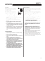
LABELS
WOODS
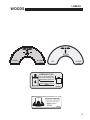
PTO SWITCH
PTO SWITCH
CHECK
ENGINE
4165638
12
4165639
LABELS
WOODS
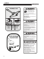
OFF
LH TANK
RH TANK
4147617
HYDRAULIC OIL
Fill to level shown with
any of the following oils:
Mineral base motor oils
15W40 or 20W50
Synthetic base motor oil
15W50
4165722
13
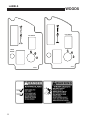
LABELS
WOODS
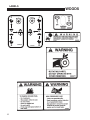
BEFORE STARTING OR SERVICING:
Read and understand the
Operator's Manual & labels.
- Be sure machine is in safe operating condition.
- Move traction levers to neutral lock, parking brake to ON.
- Set PTO switch to OFF.
BEFORE LEAVING SEAT:
- Move traction levers to neutral lock, parking brake to ON.
- Set PTO switch to OFF.
- Turn engine keyswitch to OFF.
- Remove key.
DECK SIZE
52 IN
61 IN
61 IN GENERAC
72 IN
72 IN GENERAC
BELT P/N
4165619
4165618
4165644
4165645
4165617
BLADE P/N
112111-02
112111-03
112111-03
112111-07
112111-07
4165653
LOCATED UNDER THE FLOOR PLATE
OPERATOR'S MANUAL
IS LOCATED UNDER
THE FOOT PLATE.
4165730
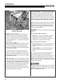
AVOID SERIOUS INJURY OR DEATH:
- Read and obey the Operation & Safety Manual.
- Remove objects that could be thrown by the blades.
- Use caution on slopes. Stay off slopes the machine
cannot back up.
- Stop blades and drive down slowly if machine slides
or stops going on slope.
- Do not mow when children or others are around.
- Do not carry a child or passenger-even with blades off.
- Look down and behind before and while backing.
- Do not operate unless trained.
- Do not operate unless guards, shields and interlocks
are in place and working.
- Replace labels and Operation and Safety Manual if lost
or damaged.
- Remove debris buildup. Debris under belt cover or
near muffler can cause fires.
- Blades continue to rotate for a few seconds after
blades are turned off.
- Blades must be at least 1/8" above bottom of housing.
- All blades must be identical. Check blade bolts daily
for tightness.
- Inspect for damage after striking a foreign object.
Make repairs before restarting operation.
- Find and repair cause of any abnormal vibration.
- Leer el manual del operador. No permitir que
personas no capacitadas para ello usen la máquina.
- Mantener los protectores en su lugar y sus tornillos
debidamente fijados.
- Antes de limpiar, ajustar o reparar este equipo,
apagar todos los mandos, aplicar el freno de
estacionamiento y apagar el motor.
- Mantener las manos, los pies y la ropa alejados de
las piezas en movimiento.
- No conducir como pasajero ni llavar pasajeros en
máquinas sin asiento para ello.
- Mantener a las demás personas alejadas durante
el funcionamiento de la máquina.
- Si no sabe leer inglés, solicitarie a otra persona
que le lea y explique el contenido de las etiquetas y
del manual de la máquina.
4165610
14
LABELS
A
TR
T
OR
P
NS
1
54
4
1
42
5
1
52
WOODS
44
2
1
44
3
31
3
4
33
AN
SP
OR
221
243
2
241
541
4
42 1
T
5
521
34 1
TR
1
121
143
41
44 3
32
4
3
141
3
4165655
34
1
1
34
22
3
24
2
1
24
1
3
12
14
1
14
1
4165654
15
1
LABELS
WOODS
F
F
N
R
16
N
4165615
N
4165616
N
R
CONTROLS
WOODS
DFI operator's right side
THROTTLE (T) - Move the throttle lever forward
to increase engine speed until the maximum governed
engine RPM is reached. Move the lever rearward to
decrease engine speed until the engine reaches its idle
speed.
KEYSWITCH (K) - The keyswitch has three
positions: OFF, RUN, and START. Insert the key and
turn it clockwise to move the switch from OFF to RUN.
Turn it further to START and hold to engage the starter.
Release the key and the switch will return to RUN from
START. Turn the key counterclockwise to OFF to stop the
engine. On the Predator Pro DFI models, if either tank
runs out of fuel, cycle the keyswitch to the ON or RUN
position 2 to 3 times, without cranking, for 10 seconds to
prime the fuel system.
CHOKE (C) - Pull the choke control out to set the
choke ON. Push it in to set the choke OFF.
ENGINE INDICATOR LIGHT (E) - A check
engine light is provided on DFI units for Kawasaki engine
dealers to diagnose engine codes. NOTE: When starting
the engine, the indicator light will come on briefly as an
engine system check. If the light continues to blink after
initial start-up, shut off engine, insure the battery cables
are connected properly and securely, and that the battery
is charged properly. Re-start the engine. If the indicator light continues to blink, contact an authorized Woods
dealer.
POWER TAKE OFF (PTO) SWITCH (P)
- The operator must be in the seat when engaging
the PTO or the engine will kill. Pulling the PTO switch
out engages (turns on) the PTO and starts the blades
or other attachment. Pushing the PTO switch in
disengages (turns off) the PTO and stops the blades or
other attachment.
NOTE: The PTO switch does not control attachments
powered by a separate engine.
– Disengage the PTO whenever you stop or leave
the operator’s position.
– Shut off engine with the key and remove the
spark plug wires before making adjustments or
unplugging a clogged mower.
– Do not engage the PTO until ready to start mowing.
HOUR METER (M) - Records accumulated
time the machine is in operation and provides
service alerts. Push and release MODE button to
toggle between functions. Provided service alerts
include change engine oil and filter, change hydraulic
oil, and service air filter. When the service time is
approaching, an alert message will flash temporarily,
interrupting whatever mode the meter is in. This will
continue until the alert is reset. When the service
interval reaches "0" hours, the word "NOW" replaces
the hours remaining. To reset the service alert,
depress and hold down the mode button for 6 seconds
while in the alert to be cleared.
17
CONTROLS
WOODS
Reverse movement - To move the machine straight
back, pull both traction levers back equally from their
neutral position. Reverse speed increases as the
levers are moved back farther. Maximum reverse
speed is reached when the levers hit the rear of the
forward-reverse slot. When moving in reverse, pushing the levers forward slows the machine, and the
machine stops when the neutral position is reached.
NOTE: Reverse is spring loaded to return to neutral.
This spring resistance may be felt when moving the
traction levers into reverse. When the levers are
released in reverse, spring tension will slowly return
them to the neutral position.
Lift and traction levers
(operator's right side)
HEIGHT OF CUT PIN (C) - Sets height of cut
and allows easy return from transport to desired
height of cut. Raise the deck to transport with the
lift lever F. Position pin C in the hole corresponding
to th desired height of cut. Lower the lift lever until it
rests on pin C.
TRACTION LEVERS (L) - Each of the two traction levers controls the drive wheel located on the
same side. They control the forward and reverse
movement of the machine, provide steering and also
provide dynamic braking.
The operator must be in the seat and the parking
brake must be OFF or the traction drive cannot be
engaged. To engage traction drive, move the traction
levers toward the center of the machine until they are
out of neutral lock slot S.
Forward movement - To move the machine straight
ahead, push both traction levers forward equally from
their neutral position. Forward speed increases as
the levers are moved farther forward from the neutral
position. Maximum forward speed is reached when
the levers hit the front of the forward-reverse slot.
When traveling forward, pulling the traction levers
rearward slows the machine, and the machine stops
when the neutral position is reached.
18
STEERING - To steer, move one lever forward and
one back.
Turns during forward movement:
– Right turn - move the right traction lever back
toward neutral to slow the right drive wheel.
– Left turn - move the left traction lever back toward neutral to slow the left drive wheel.
Turns during reverse movement:
– Reverse right turn - move the right traction lever
forward toward neutral to slow the right drive
wheel.
– Reverse left turn - move the left traction lever
forward toward neutral to slow the left drive
wheel.
Slow, sweeping turns are made with both traction
levers on the same side of neutral and slightly
apart. True zero radius turns about the center of the
machine are made by having one lever in reverse
while the other is in forward. By varying the relative
positions of the two levers, the rate of turn is varied to
suit the mowing situation.
Slow down before making sharp turns. The machine
is capable of turning very rapidly when the levers are
moved further apart from each other. Loss of control
and/or turf damage may result.
WOODS
CONTROLS
FUEL VALVES (U) - A fuel tank selector valve is
provided on oil cooler mounting bracket.The fuel tank
selector valve has three positions:
Off: The tank selector is off when the lever points toward the machine. The selector should be off whenever the machine is transported or stands unused for
any length of time. Shutting off the fuel supply avoids
the possibility of flooding should any dirt get under
the carburetor float needle. Leaving the tank selector in either tank position can allow severe flooding,
which may ruin the engine by diluting the oil.
Right Tank: Fuel flows from the right tank when the
selector is turned 1/4 turn toward the left, when facing the valve.
Left Tank: Fuel flows from the left tank when the
selector is turned 1/4 turn toward the right, when facing the vlave.
Located on oil cooler bracket behind seat.
DFI - FULE VALVES (V)- A fuel tank selector
valve is provided on the left side behind operator's
seat.
Off: The tank selector is off when the lever points to
the front of the machine. The selector should be off
whenever the machine is transported or stands unused for any length of time. Shutting off the fuel supply avoids the possibility of flooding should any dirt
get under the carburetor float needle. Leaving the
tank selector in either tank position can allow severe
flooding, which may ruin the engine by diluting the oil.
Right Tank: Fuel flows from the right tank when
the selector is turned 1/4 turn toward the rear of the
machine.
Left Tank: Fuel flows from the left tank when the
selector is turned 1/4 turn toward the left hand side of
the machine.
12 VOLT POWER OUTLET (X) - A 12 volt
power outlet is provided to operate 12 volt personal
accessories.
19
CONTROLS
WOODS
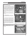
FOOT LIFT PEDAL
The foot lift pedal A, allows the operator to raise the
mower deck to the highest position without removing
his/her hands from the traction controls.
To use the foot lift pedal A, press on it to raise the
deck. The picture shows the foot lift pedal mounted
on the RH side of the machine. If you prefer to have
the foot mounted lift pedal on the left hand side,
simply loosen the existing hardware and mount the
foot lift pedal in a similar manner to the left hand side.
Tighten the hardware to secure the foot lift pedal.
PARKING BRAKE (R) - Pull the parking brake
lever up and back to put the parking brake ON. Push
it forward and down to put the parking brake OFF.
The parking brake must be ON to start the engine. It
must also be ON and the traction levers must be in
neuetral to keep the engine running if the operator
leaves the seat. The parking brake must be OFF
to keep the engine running when a traction lever is
moved out of neutral lock.
Parking brake in ON position
(operator's left side)
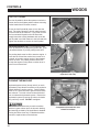
PUSHING THE MACHINE
Hydrostat bypass valves (“dump valves”) on each
hydrostatic pump allow the machine to be pushed or
towed without the engine running. Parking Brake
must be off. Raise the seat to gain access to these
two valves V. Turn both valves counterclockwise 1
turn to release the hydrostatic system. Restore the
hydrostatic system by turning the valves clockwise
only until they re-seat. DO NOT overtighten.
Use caution if it is necessary to tow the machine.
With the bypass valves open, the dynamic braking
and steering provided by the hydrostats is disabled.
Towing should be done only if a disabled machine
cannot be repaired where it broke down.
20
Compartment beneath the seat,
viewed from above
WOODS
PRE-OPERATION CHECK LIST
PRE-OPERATION CHECK LIST
(OWNER’S RESPONSIBILITY)
___ Review and follow all safety rules and safety
decal instructions.
___ Check that all safety decals are installed and in
good condition. Replace if damaged.
___ Check to make sure all shields and guards
are properly installed and in good condition.
Be sure that either the discharge shield or
complete vacuum attachment is installed.
___ Check that all hardware is properly installed.
and secured.
___ Check that equipment is properly and securely
attached to power unit.
___ Check to be sure engine is free of dirt and
debris. Pay particular attention to the cooling
fins, governor parts and muffler. Clean air
intake screen. Check air cleaner; service if
necessary.
___ Never allow riders.
___ Inspect area and remove stones, branches or
other hard objects that might be thrown,
causing injury or damage.
___ Clean area around oil fill dipstick. Remove
dipstick and check to be sure oil is in operating
range (between marks on dipstick). Add oil if
necessary but Do Not Overfill. Install dipstick
assembly firmly until cap bottoms out on tube.
Dipstick assembly must always be secured into
fill tube when engine is running.
___ Check all lubrication points and grease as
instructed in manual.
___ Check hydrostatic fluid level. Check to be sure
cooling fins on hydrostat are clean.
___ Perform a functional check of the safety
interlock system each time you operate the
unit.
21
OPERATION
WOODS
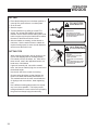
FUELING
– Fill fuel tanks with good quality, clean, unleaded
gasoline. Do not use hi-test fuel.
– Use a funnel to avoid spillage.
OPERATOR PRESENCE
INTERLOCK SYSTEM
To start the engine:
– The PTO switch must be OFF.
– Both traction levers must be in the neutral lock
position.
WARNING
– The parking brake must be ON.
To operate the machine:
1. The operator must be in the seat or engaging the
PTO will kill the engine.
TO CHECK OR ADD FUEL:
– Do it outdoors
– Do not smoke
– Stop engine; allow to cool
– Fill to one inch below bottom
of filler neck
– Do not overfill
– Clean up spilled fuel
BEFORE STARTING THE ENGINE
– Be familiar with all controls, how each functions
and what each operates.
– Check the engine oil level and add if necessary.
Open the fuel valves under each fuel tank. Select
which tank to draw fuel from with the fuel selector
valve.
– Choke: For cold starts, set the throttle lever to
the half-open position and pull the choke out to
the ON position. For warm starts set the throttle
to the half-open position and the choke to the OFF
position.
22
2. The parking brake must be OFF and the operator must be in the seat, or moving a traction lever
from the neutral lock position will kill the engine.
STARTING THE ENGINE
1. Turn the key to operate the electric starter to start
the engine. Release the key when the engine
starts.
2. If the engine does not start immediately, do not
crank for more than 10 seconds at a time. Allow
60 seconds for the starter motor to cool down
between starting attempts to prevent the starter
motor from burning out.
3. If the choke is ON when the engine starts, gradually back it off until the engine runs with no choke
at all.
OPERATION
WOODS
OPERATING NOTES
DRIVING
– Practice at slow engine and travel speeds with the
PTO off until fully familiar with the controls.
1. With the PTO disengaged, move the parking
brake to OFF.
– For normal cutting the throttle should be set at
the full open position. By using the traction levers
to speed up or slow down the machine during
use,maximum control and cutting efficiency can
be maintained.
3. Push both traction levers forward evenly to drive
forward in a straight line. Pull both traction levers
back evenly to drive backward in a straight line.
– Using the machine at less than full throttle in
heavy conditions will cause the engine to labor
and result in excessive wear tothe engine and
hydraulic system.
2. Move both traction levers out of neutral lock.
4. Steering - Move one lever forward and one back.
Turns during forward movement:
– Right turn - move the right traction lever back
toward neutral to slow the right drive wheel.
– Left turn - move the left traction lever back toward neutral to slow the left drive wheel.
Turns during reverse movement:
– Reverse right turn - move the right traction lever
forward toward neutral to slow the right drive
wheel.
– Reverse left turn - move the left traction lever
forward toward neutral to slow the left drive
wheel.
Use caution when making turns. Slow down before
making sharp turns to help maintain control and to
prevent torn turf from skidding or spinning tires. To
help prevent turf damage, keep both drive tires moving whenever a turn is made.
TIP: The best way to make a sharp "zero" turn
is to come to a stop, get the machine moving in
reverse with both drive wheels and then powering
the machine around with the outside wheel. This
technique keeps the drive tires turning and results in
less turf damage.
23
OPERATION
WOODS
CUTTING
1. Place the discharge chute in the down position or
correctly fit a grass collector or mulcher plate.
2. Sit in the seat.
DANGER
3. Start the engine.
4. Turn the blades on by pulling up on the PTO
switch. Do not start the blades at full throttle.
Instead, use the slowest throttle setting that will allow the engine to pick up the blade load to reduce
the wear on the belts and electric clutch.
5. After the blades are rotating, set the throttle to
maximum. Use the traction levers to obtain the
required cutting speed, to steer around obstacles
and to turn at the end of a cut.
ROTATING BLADES
– KEEP HANDS AND FEET AWAY.
– STOP ENGINE AND LET BLADES STOP
BEFORE REMOVING GRASS COLLECTOR OR UNCLOGGING.
WARNING
CUTTING TIPS
THROWN OBJECTS
– When mowing large areas, start by turning to the
right so that clippings will be discharged away
from shrubs, fences, driveways, etc. After two or
three rounds, mow in the opposite direction, left
hand turns, until finished.
– KEEP AREA CLEAR OF PEOPLE
AND PETS.
– REMOVE OBJECTS BLADE MAY
STRIKE AND THROW.
– STOP BLADES TO CROSS GRAVEL
AREAS
– DO NOT OPERATE WITHOUT CHUTE,
MULCHER OR ENTIRE GRASS COLLECTOR IN PLACE.
– If grass is extremely tall, it should be mowed
twice, the first cut relatively high, the second cut to
the desired height.
– Use the left side of the mower for trimming.
– Choose cutting directions so that clippings are
thrown onto areas that already have been cut.
This method results in the most even distribution
of clippings and more uniform, better appearing
cuts.
– Use a different mowing pattern each time a property is cut where possible. This helps prevent
rutting and leads to a more uniform cut by keeping
the grass from always laying the same way.
24
MAINTENANCE CHART
WOODS
MAINTENANCE
OPERATION
Maintenance is an ongoing job. These intervals are maximum times betw een
maintenance operations. Perform more often under severe conditions.
FIRST 5
HOURS
DAILY
EVERY
25
HOURS
EVERY
50
HOURS
EVERY
100
HOURS
EVERY
200
HOURS
EVERY
50 0
HOURS
ENGINE
Consult the engine manual for additional information and instructions
Check/Top Off
Engine Coolant
L evel
(Where Applicable)
Check/Top Off
Oil Level
X
X
C h ec k F o r L e a ks
X
Clean Air Intake
Screen
X
Clean Air Cleaner
Precleaner
X*
Clean Air Cleaner
Element
X
Clean Cooling Fins
X
Change Oil And
Filter
X* *
See engine manufacturer's manual
X
Check/Replace
X
Spark Plugs
* N/A IF EQUIPPED WITH HEAVY DUTY CYCLONIC AIR CLEANER
**IF EQUIPPED WITH HEAVY DUTY CYCLONIC AIR CLEANER
HYDRAULICS
C h ec k F o r L e a ks
Check/Top Off
Oil Level
Change Oil And
Filter
X
X
X
X
MACHINE
Check Interlock
Operation
X
Check Tire
Pressures
X
Check/Top Off
Battery
Lubricate All Points
X
X
X
25
MAINTENANCE RECORD
WOODS
NOTES
________________________________________________
________________________________________________
________________________________________________
________________________________________________
________________________________________________
________________________________________________
________________________________________________
________________________________________________
________________________________________________
________________________________________________
________________________________________________
________________________________________________
GENERAL
DATE
HRS
DATE
HRS
DATE
HRS
DATE
HRS
D ATE
HRS
DATE
Check Tire Pressures
Lubricate All Points
C heck Nuts & Bolts
ENGINE
Check Engine C oolant
L evel
(Where Applicable)
Check Oil Level
C hange Oil
Clean
Air Cleaner Element
Clean Cooling Fins
Replace
Air Cleaner Element
Clean & Gap
Spark Plugs
NOTE: After first 5 hours of operation replace engine oil, hydraulic oil and both filters.
26
HRS
MAINTENANCE
WOODS
CHECK DAILY
Operator Presence Interlock System - Start Operation
For the engine to crank, the parking brake must be on, the PTO (blades) off and traction levers in the neutral
lock position. Sit in the seat and check, one by one, if the engine will crank with the parking brake off, the
blades on, and either traction lever out of neutral lock.
Operator Presence Interlock System - Run Operation
The operator must be in the seat for the engine to run with the parking brake off, the traction levers moved out
of the neutral lock position, or the blades on. To check:
1. Start the engine and run at 1/2 throttle with the operator on the machine but raised off the seat.
2. One by one: move the parking brake to the OFF position, traction levers out of the neutral lock position
(check each independently), and turn the blades on. Each check should kill the engine after 1/2 second.
(A 1/2 second delay is built into the system to prevent engine cutout when traversing rough terrain.)
Repair machine before using if the Operator Presence Interlock System does not operate correctly in start or
run. Contact your authorized Schiller Grounds Care, Inc. dealer.
Hardware
Tighten any nuts and bolts found loose. Replace any broken or missing cotter pins. Repair any other problems before operating.
Tire pressure
Tires should be kept inflated at 14 lbs/in2 (1.0 kg/cm2). Improper tire inflation can cause rapid tire wear and
poor traction. Uneven inflation can cause uneven cutting.
BATTERY
Battery acid is caustic and fumes
are explosive and can cause serious injury or death.
4. Check the electrolyte level every 100 hours of
operation.
Use insulated tools, wear protective glasses or
goggles and protective clothing when working with
batteries. Read and obey the battery manufacturer’s
instructions.
5. Clean the cable ends and battery posts with steel
wool. Use a solution of baking soda and water
to clean the battery. Do not allow the solution to
enter into the battery cells.
Be certain the ignition switch is OFF and the key has
been removed before servicing the battery.
1. Verify battery polarity before connecting or disconnecting the battery cables.
6. Tighten cables securely to battery terminals and
apply a light coat of silicone dielectric grease to
terminals and cable ends to prevent corrosion.
Keep terminal covers in place.
2. When installing the battery, always assemble
the RED, positive ( + ) battery cable first and the
ground, BLACK, negative ( - ) cable last.
3. When removing the battery, always remove the
ground, negative ( - ) cable first and the red, positive ( + ) cable last.
27
MAINTENANCE
WOODS
6
1
2
2
4
2
5
3
2
4
2
6
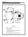
LUBRICATION
Every 50 hours of operation, lubricate the following points (1-4) with
grease:
1. Deck lift rockshaft (1 point)
2. Deck lift pivots (6 points)
3. Brake lever pivot (1 point)
4. Push arms (2 points located at rear of cutterdeck under each fuel tank)
5. Isolation mounts (4 points located under seatt at front of machine)
6. Caster wheel pivots (2 points)
(Lubricate every 500 hours or once a year)
NOTE ON BLADE SPINDLES - The blade spindles on these machines
use a superior sealed bearing that does not require relubrication.
28
WOODS
MAINTENANCE
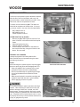
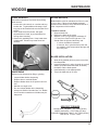
HYDRAULIC SYSTEM
Fluid level in the hydraulic system should be checked
after the first 5 hours of operation, and every 100
hours thereafter, or when a leak has occurred. If the
fluid is low, check all components for leaks.
To check, remove reservoir cap M. The fluid level
should be at the bottom of the filler tube. If low, top
up (do not overfill). Use one of the oils listed below:
– SAE 15W40 motor oil
– SAE 20W50 motor oil
– 15W50 synthetic motor oil
AFTER FIRST FIVE (5) HOURS
1. Remove plug N to drain hydraulic reservoir. Dispose of used oil in accordance with local requirements.
2. Clean and replace the plug.
3. Change hydraulic oil filter G.
4. Fill the reservoir with fresh oil to the bottom of
the reservoir filler tube, using an oil from the list
above. Do not overfill.
PERIODIC OIL CHANGES
Change the hydraulic fluid and hydraulic filter
after each 500 hours of operation using the same
procedure given above.
NOTES:
Before servicing the hydraulic system, stop the engine,
disconnect spark plug wires and disengage the PTO.
– After any hydraulic line is opened, plug or cap it
promptly to reduce the risk of contamination.
– Do not use sealant tape on hydraulic pipe fittings.
Use a liquid sealant that will dissolve into the
system.
– Make sure all hydraulic connections are tight and
hydraulic hoses and lines are in good condition
before applying pressure to system.
View from below machine
The machine's hydraulic system operates under high
pressure. When checking for leaks, do not use your
hands to attempt to find a leak. Instead, use cardboard or paper. Escaping hydraulic fluid can be under
sufficient pressure to penetrate skin and cause serious
injury. If hydraulic fluid is injected into the skin, it must
be promptly removed by a doctor familiar with this form
of injury or gangrene may result.
29
MAINTENANCE
WOODS
ENGINE OIL
Do not perform engine maintenance without the
engine off, spark plug wires disconnected and PTO
disengaged.
AFTER FIRST FIVE (5) HOURS
While the engine is warm:
1. Release the oil drain hose assembly from the
engine clip J. Lay hose assembly over the frame
edge.
2. Remove the rubber cap D from the tip of the
hose assembly and turn the drain valve to allow
oil to drain from the engine. Dispose of used oil
in accordance with local requirements.
3. Clean drain valve and tighten the plastic portion
of the drain valve back into the metal portion of
the valve. Replace rubber cap over the tip of the
valve. Replace hose assembly back into engine
clip.
4.
Change oil filter.
5. Fill the crankcase with fresh oil to the full mark.
Do not overfill. See engine manual for oil
specifications.
DAILY
1. Check oil level with the dipstick.
2. If oil is needed, add fresh oil of proper
viscosity and grade. See engine manual for oil
specifications. Do not overfill.
3. Replace dipstick before starting engine.
PERIODIC OIL CHANGES
1. See engine manual for oil and filter change intervals after the break-in period.
2. Follow instructions for first oil change, above.
SPARK PLUGS
Remove each plug and check condition.
– Good operating conditions are indicated if the plug has a light coating of grey or tan deposit.
– A white blistered coating indicates overheating. A black coating indicates an “over rich” fuel mixture. Both
may be caused by a clogged air cleaner or improper carburetor adjustment.
– Do not sandblast, wire brush or otherwise attempt to repair a plug in poor condition. Best results are
obtained with a new plug.
– Set plug gap as specified in engine manual..
FUEL FILTER
An inline fuel filter is located in the fuel supply line. Inspect at every oil change to make sure it is clean and
unobstructed. Replace if dirty.
30
WOODS
MAINTENANCE
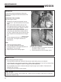
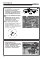
ENGINE COOLING
Continued operation with a clogged cooling system
will cause severe overheating and can result in engine damage.
-
Daily: Clean air intake screen S on air cooled
engines and T on liquid cooled engines.
-
Every 100 hours: Clean cooling fins beneath
blower housing H with reference to information in
the engine manufacturer's manual.
HEAVY DUTY CYCLONIC AIR CLEANER
Clean and replace the air cleaner element as
specified in the service chart. Uneven running, lack
of power or black exhaust fumes may indicate a dirty
air cleaner.
To replace air cleaner elements:
1. Unclamp end cover X and remove existing
cleaner elements.
2. Insert new elements Y and Z and replace cover.
Ensure the breathing port A is pointing down and
towards the front of the tractor.
31
MAINTENANCE
CLEANING MACHINE
Clean the machine after use. The machine will run
cooler and last longer if kept free of clippings and
other debris. A clean machine also reduces the risk
of fire due to accumulation of combustible debris and
chaff
Brush or blow clippings and debris off the cutterdeck
and engine deck.
WASHING MACHINE
CAUTION: Improperly washing a machine can cause
water to enter bearings and other components. This
can greatly reduce component life.
– Do not use a pressure washer. Do not direct
water at bearings or seals. High pressure water
can blow past seals ad enter seal bearings.
– Allow the machine to cool down before washing.
Water on a warm machine can be sucked into
sealed bearings as they cool.
– Avoid getting electrical connections wet. Water
can cause electrical faults and corrosion of electrical components.
32
WOODS
MAINTENANCE
WOODS
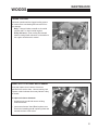
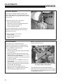
BLADE REMOVAL
BLADE BALANCE
Follow these instructions to prevent injury during
blade removal:
1. Loosen with a box wrench or a socket and long
breaker bar. To gain additional leverage, slip a
long pipe or thick-walled tube over breaker bar or
wrench.
2. Insert wood block A as shown, with grain
perpendicular to blade, to prevent blade from
turning when loosening.
3. Wear thickly padded gloves. Keep hands clear
of blade path. Blades may rotate when bolt
releases.
Blade balance must be maintained at 5/8 oz-in (19.4
g-cm) or less. Failure to keep blades balanced
causes excess vibration, wear, and shortened life of
most components of the machine.
To balance a blade:
1. Sharpen blade first.
2. Balance the blade at the center.
3. Attach a 1/8 oz (3.9 g) weight at a distance 5"
(127 mm) from center on the light end. This
should make the light end the heavy end:
– If it does, the blade is balanced.
– If does not, file or grind the heavy end until
the addition of the weight makes the light end
the heavy end.
BLADE INSTALLATION
SHARPENING
1. Wear thickly padded gloves to prevent cuts from
the sharp blade.
2. Insert the blade bolt, in order, through the conical
washer (cup side toward the blade, as shown),
the blade, and the blade spacer.
3. Install assembly on the blade spindle.
4. Torque the blade bolt to 70 ft-lbs.
Blades may be sharpened by filing or grinding.
– Inspect blades before sharpening.
– Replace bent or cracked blades.
– Replace blades when the lift portion has worn
thin.
– Maintain cut angle at 30o.
– Do not overheat blades when sharpening.
– Always use Schiller Grounds Care, Inc. blades.
Use of another manufacturer’s blades may be
dangerous.
SPECIFIC TORQUES
BLADE BOLT TORQUE: 70 FT-LBS (95 Nm)
WHEEL HUB NUTS: 175 FT-LBS (237 Nm)
ENGINE CRANKSHAFT BOLT: 50 FT-LBS (68 Nm)
LUG NUTSl 75-100 FT-LBS
33
ADJUSTMENTS
DECK LEVELING
1. Park the machine on a smooth, level surface.
Raise the deck to the transport position.
2. Lower the deck onto a set of equal height blocks
A under the rear corners of the deck. Place another set of blocks B under the front of the deck
so that the deck top is pitched forward 1/8".
NOTE: The front and rear of the deck are at different
heights.
3. Measure the height of the blade cutting edge
above the ground. Remove pin C and set the
height of cut lever D to that height.
4. Loosen nuts I at all four corners of the deck.
NOTE: This will relieve tension on chains H.
5. Loosen the jam nuts E on the height of cut clips F and adjusting screws G. Turn the adjusting screws G until the play is taken out of the
chains H at all four corners. Tighten the jam nuts
E against the clips F and at the adjusting screws
G. Retighten nuts I at this time.
COUNTERBALANCE SPRINGS
1. Raise the cutterdeck all the way.
2. Adjust the spring A with nut B: The spring length
should be set at approximately 8-3/4", inside loop
to inside loop, when in transport position.
34
The springs may be tightened or loosened from
this point according to personal preference.
WOODS
WOODS
ADJUSTMENTS
HEIGHT OF CUT
The height of cut is set by moving height of cut pin C
to the hole designated for the height of cut desired.
To change the height of cut:
1. Lift the deck to the highest position.
2. Move pin C to the selected hole.
3. Lower the deck until the lift lever is stopped by
the pin.
NOTES:
– Height of cut may vary due to the amount of
tread on the tires, tire diameter or inflation pressure. Rear wheels 12 p.s.i.
– For best results, adjust the rear deck rollers for
the height of cut to be used (see below).
REAR DECK ROLLERS
The rear outside deck rollers are adjustable up and
down to provide improved deck flotation and scalping protection at various heights of cut. They are not
intended to ride continuously on the ground. Adjust
no closer than 3/8" (10mm) to the ground.
Height of cut ranges for roller adjustment
FRONT DECK LIP
Adjustable front deck lips have been provided on 52
in. and 61 in. cutterdecks for various cutting conditions.
To revise per conditions:
1. Loosen the front bolts S.
2. Adjust height of H.
3. Retighten S once you have desired height.
35
ADJUSTMENTS
WOODS
CONTROL LEVERS
There are two mounting positions for the control
levers, upper and lower. The lower position works
well for most people. Taller operators may need the
upper position.
To adjust the height of the control levers:
– Remove bolts A and nuts B.
– Align holes in control lever D with appropriate
holes in traction lever bracket C.
– Install bolts A and nuts B.
The upper mounting hole for the control levers is
slotted to allow fore-aft adjustment and to allow
alignment of the levers.
To adjust or align the control levers:
– Loosen nuts B.
– Adjust control lever position.
– Tighten nuts B.
PARKING BRAKE
Park machine on a smooth level surface.
NOTE: Parking brake must be in the OFF position to
properly seat brake drums.
Support the machine with the rear wheels off the
ground, using jack stands or equivalent. DO NOT
rely on mechanical or hydraulic jacks.
1. Remove rear wheels.
2. Measure spring length O with parking brake N in
the OFF position.
3. Move parking brake N to the ON position and
measure length of spring O again. When spring
deflects 3/8" it is properly adjusted.
4. If adjustment is required, return parking brake N
to the OFF position.
5. Disconnect one end of rod M at the brake and
loosen jam nut.
6. Adjust rod M in or out as required until 3/8" deflection in brake spring O is achieved with parking brake N in the ON position.
7. Reconnect rod M and retighten jam nut.
8. Repeat steps 2-7 on opposite side of machine.
9. Replace wheels and tighten wheel nuts.
36
Parking brake assembly (tire and deck not shown
for clarity - brake in ON position).
This adjustment will cause the brake springs to
stretch 3/8" when the parking brake is in the ON position, providing the correct parking brake force without
overloading the brake arm.
WOODS
ADJUSTMENTS
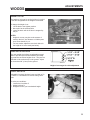
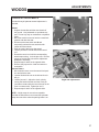
HYDROSTAT ADJUSTMENTS
A turnbuckle-style hydrostat neutral adjustment is
provided.
Neutral:
1. Support the machine with the rear wheels off
the ground. Use jackstands or equivalent support. Do not rely only on mechanical or hydraulic
jacks.
2. Move the traction levers out into the neutral lock
position and raise the seat.
3. Disconnect the seat switch wire K and
temporarily connect the two terminals with
jumper wire J as shown.
4. Start the engine and run at low speed.
5. Loosen jam nuts T at both ends of the control
rod.
6. Rotate the control rod until the corresponding
wheel stops turning. Lock the jam nuts. Run the
engine up to high idle to check the adjustment.
Readjust if necessary.
7. Repeat steps 5 and 6 for the opposite side.
8. Remove the jumper wire J and reconnect the
seat switch.
Reverse Return:
1. Move traction levers out to the neutral lock position and raise the seat.
2.Locknut U should be run on the bolt as far as it
will go.
3. Loosen jam nut Y. Adjust the clevis yoke by
turning the head of the bolt until the clevis pin
just makes contact with the rear of the slot in the
lever it connects with. Tighten jam nut Y.
Right side adjustments
4. Repeat steps 2 and 3 for the opposite side.
NOTE: A slight creep in reverse is acceptable
provided the wheel does not turn and the hydrostat
pump does not whine when the parking brake is on.
37
ADJUSTMENTS
WOODS
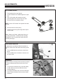
CUTTERDECK BELT
1. Tilt floorplate all the way forward.
2. Set the cutterdeck in a middle height-of-cut position.
3. Use a 3/8" ratchet and extension to back
tensioning idler off to remove belt from idler.
Remove belt from cutterdeck pulleys.
NOTE: Use the 3/8" ratchet in the square hole A on
the idler.
4. Remove belt from clutch pulley.
5. Install the new belt by performing these steps in
reverse order.
Note: Always use Woods. replacement belts, not
general purpose belts. Woods belts are specially
designed for use on commercial mowers and will
normally last longer.
TRACKING HANDLES
An adjustment is provided to allow the operator to
align the control levers with each other during operation.
1. Turn knob W clockwise to shorten control lever
travel.
2. Turn knob W counter-clockwise to increase control lever travel.
DAMPERS
Different damper mounting holes have been provided
for various operator preferences with control lever
motion.
1. For a stronger resistance feel, mount the dampers X in the outer most hole Z of the motion
control weldment.
2. For a lighter resistance feel, mount the dampers
X in the inner most hole V of the motion control
weldment.
38
A
WOODS
BELT REPLACEMENT
PUMP-DRIVE BELT
1. Remove engine-cutterdeck belt (see engine-cutterdeck belt replacement).
2. Attach an extension to a 3/8" drive ratchet. Insert the ratchet extension in the square hole of the pump
drive idler arm. Use the ratchet handle to rotate it enough to remove the pump drive belt.
3. Install a new pump drive belt in the same manner as it was removed.
4. Re-install engine-cutterdeck belt (see engine-cutterdeck belt replacement).
39
LIMITED WARRANTY
(Mow’n Machine Zero-Turn Mowers and Woods Boundary Utility Vehicles)
TM
TM
Please Enter Information Below and Save For Future Reference.
Date Purchased: __________________________
From (Dealer):______________________________________
Model Number: __________________________
Serial Number: _____________________________________
WHAT IS COVERED:
Woods Equipment Company (“WOODS”) warrants Mow’n MachineTM zero-turn mowers and attachments and Woods BoundaryTM utility
vehicles, accessories and attachments to be free from defect in material and workmanship for the warranty periods listed below.
FOR HOW LONG:
Mow’n Machine Model #CZ1736K, CZ1948K, CZ1952K, CZ2361, ME1952K, ME2661B, MZ2552K, MZ2561K, MZ2761, MZ3761K,
MZ3772K, MZ2661KL & attachments are warranted for two (2) years from the date of delivery to the original purchaser or 2000 hours of
operation, whichever occurs first. Purchaser may opt for a warranty of five (5) years from the date of delivery to the original purchaser or 500
hours of operation, whichever occurs first. The dealer must specify the special warranty term on the original, dated bill of sale and a copy must
be provided with all warranty claims. Mow’n Machine model numbers CZR2242B and CZR2652B are warranted for residential use for three (3)
years from the date of delivery to the original purchaser or for commercial use for 90 days from the date of delivery to the original purchaser..
Mow’n Machine Model #FE21B, FZ21D, FZ23B, FZ25D, FZ28K & attachments are warranted for two (2) years from the date of delivery to the
original purchaser or 2000 hours of operation, whichever occurs first.
In addition, Mow’n Machine ME and MZ Series Models, serial number XXXXXXXX300 and above, have a Limited Lifetime Warranty on deck,
deck cradle, and engine deck for the life of the machine to the original retail purchaser.
Woods Boundary utility vehicle Model #MAV350, MAV480, MAV4x4, accessories & attachments are warranted for two (2) years from the date
of delivery to the original purchaser.
IMPLIED WARRANTIES OF MERCHANTABILITY AND/OR FITNESS FOR A PARTICULAR PURPOSE ARE LIMITED IN DURATION
TO THE DURATION OF THE WRITTEN WARRANTY PERIODS LISTED ABOVE. Some states do not allow limitations on how long an
implied warranty lasts, so the above limitation may not apply to you.
WHO IS COVERED:
This Warranty is extended solely to the original purchaser of the product. Should the original purchaser sell or otherwise transfer the product to a
third party, this Warranty does not transfer to the third party purchaser in any way. There are no third party beneficiaries of this Warranty.
WHAT IS NOT COVERED:
This Warranty does not cover normal wear or tear, or normal maintenance items, or any damage, failure or loss caused by:
1. Improper operation, improper maintenance, misuse, or an accident;
2. Any modification or repair by someone other than WOODS, a WOODS’ authorized dealer or distributor, and/or a WOODS’
authorized service center; or
3. Repairs made with parts other than those obtained through WOODS.
WOODS makes no warranty, express or implied, with respect to engines, batteries, tires or other parts or accessories with respect to which the
manufacturer provides a separate warranty.
WHAT WOODS WILL DO TO CORRECT PROBLEMS:
WOODS’ obligation under this Warranty is limited to, at WOODS’ option, the repair or replacement, free of charge, of the product if the product
is defective or in noncompliance with this Warranty. The product must be returned to WOODS with proof of purchase within thirty (30) days
after such defect or noncompliance is discovered or should have been discovered, routed through the dealer and distributor from whom the
purchase was made, transportation charges prepaid. WOODS shall complete such repair or replacement within a reasonable time after WOODS
receives the product.
OTHER LIMITATIONS:
WOODS shall not be liable for any incidental or consequential losses, damages or expenses, arising directly or indirectly from the
product, whether such claim is based upon breach of contract, breach of warranty, negligence, strict liability in tort or any other legal
theory. Without limiting the foregoing, WOODS shall not be liable for any damages relating to (i) lost profits, business, revenues or goodwill;
(ii) any expense or loss incurred for labor, supplies, substitute machinery or rental; or (iii) any other type of damage to property or economic loss.
Some states do not allow the exclusion or limitation of incidental or consequential damages, so the above limitations may not apply to you.
No agent, representative, dealer, distributor, service person, salesperson, or employee of any company, including without limitation, WOODS, its
authorized dealers, distributors, and service centers, is authorized to alter, modify, or enlarge this Warranty.
HOW STATE LAW APPLIES:
This Warranty gives you specific legal rights, and you may also have other rights which vary from state to state.
QUESTIONS:
Answers to any questions regarding warranty service and locations may be obtained by contacting:
Woods Equipment
Company
2606 South Illinois Route 2
Post Office Box 1000
Oregon, Illinois 61061
800-319-6637 tel
800-399-6637 fax
www.WoodsEquipment.com
F-8045 MM & Boundary (Rev. 12/1/2008)
LIMITED WARRANTY
(Mow’n MachineTM Zero-Turn Mower and
Woods BoundaryTM Utility Vehicle Replacement Parts)
Woods Equipment Company (“WOODS”) warrants replacement parts for Mow’n Machine zero-turn
mowers and attachments and Woods Boundary utility vehicles, accessories and attachments to be free
from defect in material and workmanship for a period of ninety (90) days from the date of delivery of the
product to the original purchaser.
TM
TM
IMPLIED WARRANTIES OF MERCHANTABILITY AND/OR FITNESS FOR A PARTICULAR
PURPOSE ARE LIMITED IN DURATION TO A PERIOD OF NINETY (90) DAYS FROM THE
DATE OF DELIVERY OF THE PRODUCT TO THE ORIGINAL PURCHASER. Some states do not
allow limitations on how long an implied warranty lasts, so the above limitation may not apply to you.
This Warranty is extended solely to the original purchaser of the product. Should the original purchaser
sell or otherwise transfer the product to a third party, this Warranty does not transfer to the third party
purchaser in any way. There are no third party beneficiaries of this Warranty.
This Warranty does not cover normal wear or tear, or normal maintenance items, or any damage, failure
or loss caused by improper operation, improper maintenance, misuse, or an accident.
WOODS’ obligation under this Warranty is limited to, at WOODS’ option, the repair or replacement,
free of charge, of the product if the product is defective or in noncompliance with this Warranty. The
product must be returned to WOODS with proof of purchase within thirty (30) days after such
defect or noncompliance is discovered or should have been discovered, routed through the dealer
and distributor from whom the purchase was made, transportation charges prepaid. WOODS
shall complete such repair or replacement within a reasonable time after WOODS receives the product.
WOODS shall not be liable for any incidental or consequential losses, damages or expenses,
arising directly or indirectly from the product, whether such claim is based upon breach of
contract, breach of warranty, negligence, strict liability in tort or any other legal theory. Without
limiting the foregoing, WOODS shall not be liable for any damages relating to (i) lost profits, business,
revenues or goodwill; (ii) any expense or loss incurred for labor, supplies, substitute machinery or rental;
or (iii) any other type of damage to property or economic loss. Some states do not allow the exclusion or
limitation of incidental or consequential damages, so the above limitations may not apply to you.
No agent, representative, dealer, distributor, service person, salesperson, or employee of any company,
including without limitation, WOODS, its authorized dealers, distributors, and service centers, is
authorized to alter, modify, or enlarge this Warranty.
This Warranty gives you specific legal rights, and you may also have other rights which may vary from
state to state.
Answers to any questions regarding warranty service and locations may be obtained by contacting:
Woods Equipment
Company
2606 South Illinois Route 2
Post Office Box 1000
Oregon, Illinois 61061
800-319-6637 tel
800-399-6637 fax
www.WoodsEquipment.com
F-8495 MM & Boundary Repair Parts (Rev. 2/15/2006)
Woods Equipment
Company
2606 South Illinois Route 2
Post Office Box 1000
Oregon, Illinois 61061
800-319-6637 tel
800-399-6637 fax
www.WoodsEquipment.com
©2008 Woods Equipment Company. All rights reserved. WOODS, the Woods logo, and “Tested. Proven. Unbeatable.” are trademarks
of Woods Equipment Company. All other trademarks, trade names, or service marks not owned by Woods Equipment Company that
appear in this manual are the property of their respective companies or mark holders. Specifications subject to change without notice.