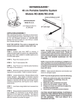
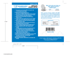
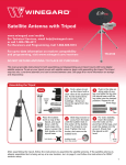
1
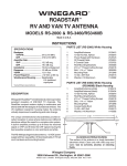
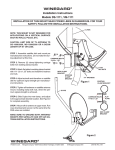
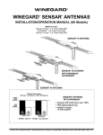
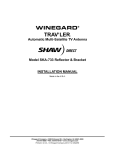
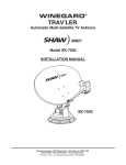
MODEL RS-1500
OMNIDIRECTIONAL TV/FM ANTENNA
NOTE: Please read all instructions before beginning installation!
WARNING!
To prevent FIRE or SHOCK HAZARD, avoid exposure of power
supply to moisture.
PARTS LIST
1. (1) Antenna
2. (1) 15' RG-6 Low Loss Coax Cable
3. (1) Cable Tool
4. (1) Power Supply RV-7542
5. (4) 1/4-20 Hex Flange Nuts
6. (4) 1/4-20 Carriage Bolts
7. (2) Insulated Quick-Disconnect
Terminals
8. Mount
9. (4) Lag Screws 1/4” x 1-1/4”
10. (4) Washers 1/4”
11. (1) Roof Gasket
12. (1) Cable Gasket Plug
13. (1) Antenna Gasket
#5. HEX FLANGE NUTS
#1. ANTENNA
#6. CARRIAGE
BOLT
#13. ANTENNA
GASKET
#9. LAG SCREWS
#4. POWER SUPPLY
AND SCREWS
#10. WASHERS
#8. MOUNT
#12. CABLE
GASKET PLUG
#11. ROOF GASKET
TOOLS NEEDED
#2 Phillips screwdriver
7/16” wrench
Medium slot screwdriver
Cable tool
Wire stripper
#7. INSULATED QUICK
DISCONNECT TERMINALS
#2. COAX CABLE
CABLE PROVIDED
BY INSTALLER FOR RV
MANUFACTURER
INSTALLED UNITS.
#3. CABLE TOOL
NOT INCLUDED WITH
RV MANUFACTURER
INSTALLED UNITS.
Winegard Company • 3000 Kirkwood Street • Burlington, IA 52601 • 319/754-0600 Fax 754-0787 • www.winegard.com
Printed in U.S.A. © 2002,2005 Winegard Company 2451233 Rev5 10/10
The Parts:
ANTENNA
OPTION 2: Run cable supplied down through mount
base and out open slot in base of antenna mount. See
Option 2 figure below. Finish routing cable to wall plate.
OPTION 2
OPTION 1
1” DIAMETER MOUNT
& SCREWS (provided).
INSTALL CABLE
GASKET PLUG
ANTENNA MOUNTING
BRACKET
COAXIAL CABLE
CABLE GASKET PLUG
LARGE MOUNT
GASKET
BEFORE YOU BEGIN:
Decide location of power supply before
mounting your antenna.
A wiring diagram, Figure 1, will help you determine the
location for your antenna and power supply. Antenna
and power supply location determines where and
how you run cables.
DO NOT begin installation before carefully reading
all installation instructions.
FIGURE 1
DO NOT USE
CABLE GASKET
PLUG
LARGE MOUNT
GASKET
SMALL ANTENNA
GASKET
1” DIAMETER MOUNT
& SCREWS (provided).
1” DIAMETER MOUNT
& SCREWS (provided).
LARGE MOUNT
GASKET
REMOVE SMALL
ANTENNA GASKET
REMOVE SMALL
ANTENNA GASKET
ATTACHING MOUNT TO ROOF
Securely fasten antenna mount to roof making sure to place
large mount gasket between mount and roof, using the 4
sets of washers and lag screws supplied. Seal around
mount base and over screw heads with approved sealant
for your roof. Contact the manufacturer of your RV.
CONNECTING COAX CABLE TO THE ANTENNA
1.Slide small antenna gasket (previously removed from
the middle of the large mount gasket) onto coax.
2.Slide coax cable (with connector installed) into cable
tool through the slot in the side of the tool, hex end up,
Figure 2.
FIGURE 2
FIGURE 3
CABLE
CONNECTOR
FLUSH WITH
END OF
CABLE TOOL
CABLE
TOOL
COAXIAL
CABLE
ANTENNA
ANTENNA
GASKET
TV
15’ COAX
CABLE
(SUPPLIED) *
*IF A LONGER CABLE IS
NEEDED, USE A LENGTH
OF RG6/U COAX.
+
-
+12 VDC
Source
12 GA WIRE
(Not provided)
POWER
SUPPLY
BEFORE INSTALLING ANTENNA MOUNT, CHOOSE
ONE OF THE FOLLOWING MOUNTING OPTIONS
THAT BEST SUITS YOUR INSTALLATION NEEDS.
Start by removing the small antenna gasket from the
center of the large mount gasket. Save it for later
use. See either of two Option figures in next column.
OPTION 1: Drill 5/8” hole through roof. Run cable
through roof up center of large mount gasket and antenna mount. See Option 1. Install cable gasket plug in
base. Route cable from antenna to wall plate.
3. Push the cable up until the end of the connector is
flush with the hex-shaped end of the cable tool. See
Figure 3.
4. Insert the cable tool with cable attached into the
mounting bracket on the underside of the antenna,
aligning the end of the connector with the cable
connection on the antenna. Push up until you feel a
SLIGHT resistance.
5. Turn cable tool to the right until the connector is
tight.
6. Remove cable tool.
INSTALLING ANTENNA ON MOUNT
1. After cable connection is made, slide antenna gasket
down coax to top of mount. Then slide antenna onto
mount. GENTLY pull back any extra cable inside vehicle.
2. Fasten antenna to mount using 1/4-20 carriage bolts
(#6) and hex flange nuts (#5). Tighten firmly to prevent
antenna from turning on mount or mast.
CONNECTING POWER SUPPLY
1. Select location for power supply. Run two coax cables
(three if Set 2 jack is going to be used) (RG-59 type)
between locations and install connectors on each end.
Mark cables so "cable input", "TV output" "Set 2"
may be identified. Antenna downlead and +12 VDC
also needed at inside power supply location. See wiring
diagram, Figures 5 and 6.
2. To mount the power supply, cut a hole in wall to fit the
power supply. Connect 2 #12 wires between power
supply and +12 VDC source and route downlead cable
to this location.
FIGURE 5
(Wiring diagram)
2ND Set
Hook Up
No +12 VDC
at this point
Auxillary
Satellite Receiver
Connection
Amplified
TV Signal
+12 VDC
Set 2
CAUTION: TURN OFF POWER SUPPLY WHEN
CONNECTING CABLES/WIRES!
3. Connect +12 VDC to wall plate/power supply. Install
terminals on wires from +12 VDC source as shown in
Figure 7.
4. Crimp terminals with crimping tool, Figure 8. Push
wires onto tabs on terminal board as shown in Figure 6.
If in doubt as to the polarity of the wires, connect them
temporarily to tabs on circuit board and press ON switch
on front of wall plate; if light comes on polarity is correct.
5. Install connectors on downlead, Set 2 and Cable Input
cables. Attach downlead cable to jack on wall plate/
power supply marked Antenna as shown in Figures 5
and 6. Attach cable going to Set 2 outlet to jack on
power supply marked SET 2. Attach cable coming from
cable input to jack on power supply marked CABLE.
5. Mount power supply in wall with screws provided; attach
TV set cable to jack on front of power supply/wall plate.
Press ON switch on front of wall plate and check that light
is on.
Antenna
Connection
Cable
Red
+12 VDC
White
GND.
IMPORTANT
Positive and Negative leads from Battery must
be connected to the control box terminals
exactly as shown
FIGURE 6
AUXILLIARY
FOR
SATELLITE
RECEIVER
TO MAIN TV
CHECKING OPERATION OF POWER SUPPLY
1. Tune TV receiver to nearest station and rotate antenna
for best picture and sound.
2. Press OFF switch on power supply. Picture on TV
should be considerably worse with power off.
3. This unit is equipped with a polyswitch (current
limiting device) which will shut down +12 VDC if there is a
direct short between antenna and power supply. Red
indicator light will not light. Once short is eliminated,
device will reset itself.
SET 2
OUTPUT
ATTACH
+12 VDC
ANTENNA
DOWNLEAD HERE
FIGURE 7
ATTACH -12VDC
(GROUND)HERE
CABLE/SATELLITE
INPUT
Crimp Here
1/4"
Connector
Insulation Crimp Here
FIGURE 8
3
Connector
Ferrule
#12 Wire
Remove 1/4"
insulation from
#12 wire.
WHAT TO DO WHEN YOUR RV/TV ANTENNA IS NOT WORKING PROPERLY
WARNING
DO NOT install couplers, splitters, etc. between power
supply and antenna. Installation of any item on the
downlead MAY CAUSE A SHORT IN THE SYSTEM. The
downlead supplies +12 VDC to preamp in antenna.
HOW YOUR SYSTEM WORKS
2ND Set
Hook Up
No +12 VDC
at this point
Auxillary
Satellite Receiver
Connection
HOW YOUR SYSTEM WORKS
Turning power supply on sends +12 VDC up cable to
antenna. Voltage energizes transistors on amplifier in
antenna head. TV signal comes back down cable to
outlets.
TO TEST SYSTEM
1. Make sure TV set is working properly.
2. Switch power supply ON and OFF to see if there is a
difference in the picture quality while watching TV. If NO
difference, use following steps.
+12 VDC
CAUTION!
The power supply should be turned OFF when connecting/disconnecting cables to power supply and antenna,
turned ON when testing for voltage.
3. Disconnect cable from antenna and check for +12 VDC
at Test Point #1. If there is +12 VDC, the power supply is
OK and the antenna needs to be replaced.
4. If there is NO +12 VDC at Test Point #1,reconnect
cable to antenna. Remove power supply from wall and
inspect for burned/broken parts. If there are ANY broken
or burned parts, replace power supply.
6. If +12 VDC is not present at Test Point # 2, check
green indicator light. If it is not ON, check the polarity of
the red/white wires and +12 VDC source. If there is still
no +12 VDC, replace power supply.
Coax
Jack
Set 2
Antenna
Connection
Cable
Red
+12 VDC
TO TEST SYSTEM
TEST POINT #1
White
GND.
+12 VDC at Antenna
+ Point center wire
- Point outside of connector
2ND Set
No +12 VDC
at this point
Auxillary
Satellite Receiver
Connection
5. Disconnect cable from antenna jack on power supply.
Check for +12 VDC Test Point 2. If +12 VDC is present,
there is a problem in the cable connecting the power
supply to the antenna. Repair or replace cable.
NOTE: Power supplies manufactured after October
1991 have a polyswitch. The polyswitch shuts the
power supply off if a short in the cable is detected
and will reset itself in approximately two minutes
after the short is removed.
Amplified
TV Signal
+12 VDC
at
Antenna
Jack
Set 2
Connection
TEST
POINT #2
Red
+12 VDC
White
GND.
WINEGARD MOBILE PRODUCTS LIMITED WARRANTY
(2 YEARS PARTS; 1 YEAR LABOR)
Winegard Company warrants this product against defects in materials or workmanship for a period of two (2) years from the date of original purchase. During year one (1) of such
warranty, Winegard Company will also pay authorized labor costs to an authorized Winegard dealer to repair or replace defective products. No warranty claim will be honored unless
at the time the claim is made, Customer presents proof of purchase to an authorized Winegard dealer (to locate the nearest authorized Winegard dealer, contact Winegard Company,
3000 Kirkwood Street, Burlington, Iowa 52601, Telephone 800-288-8094 or visit www.winegard.com). Customer must provide proof of purchase with a dated sales receipt for the
Winegard product to verify the product is under warranty. If the date of purchase cannot be verified, the warranty period shall be considered to begin thirty (30) days after the date
of manufacture.
If a defect in material or workmanship is discovered, Customer may take the product to an authorized Winegard dealer for service. Customer must provide proof of purchase to
verify the product is under warranty. If the product is brought to an authorized Winegard dealer for service prior to expiration of year one (1) of the warranty period and a defect in
material or workmanship is verified by Winegard Technical Services, Winegard Company will cover the Winegard dealer’s labor charges for warranty service. The Winegard dealer
must contact Winegard Technical Services in advance for pre-approval of the service. Approval of the service is at the sole discretion of Winegard Company.
Alternatively, Customer may ship the product prepaid to Winegard Technical Services (located at 3111 Kirkwood Street, Burlington, Iowa 52601, Telephone 800-788-4417). Customer
must return the product along with a brief description of the problem and provide Winegard Technical Services with Customer’s name, address, and phone number. Customer must
also provide proof of purchase to verify the product is under warranty. If the product is returned before the expiration of the warranty period, Winegard Company will (at its option)
either repair or replace the product.
This Limited Warranty does not apply if the product has been damaged, deteriorates, malfunctions or fails from: improper installation, misuse, abuse, neglect, accident, tampering,
modification of the product as originally manufactured by Winegard in any manner whatsoever, removing or defacing any serial number, usage not in accordance with product
instructions or acts of nature such as damage caused by wind, lightning, ice or corrosive environments such as salt spray and acid rain. This Limited Warranty also does not apply
if the product becomes unable to perform its’ intended function in any way as a result of the television signal provider making any changes in technology or service.
RETURN AUTHORIZATION POLICY
A Return Material Authorization (RMA) is required prior to returning any product to Winegard Company or Winegard Warranty Services under this warranty policy. Please call our
Technical Services Department at 800-788-4417 or send an e-mail to [email protected] to obtain the RMA number. Please furnish the date of purchase when requesting an
RMA number. Enclose the product in a prepaid package and write the RMA number in large, clear letters on the outside of the package. To avoid confusion or misunderstanding, a
shipment(s) without an RMA number(s) or an unauthorized return(s) will be refused and returned to Customer freight collect.
WINEGARD COMPANY DOES NOT ASSUME ANY LIABILITIES FOR ANY OTHER WARRANTIES, EXPRESS OR IMPLIED, MADE BY ANY OTHER PERSON.
ALL OTHER WARRANTIES WHETHER EXPRESS, IMPLIED OR STATUTORY INCLUDING WARRANTIES OF FITNESS FOR A PARTICULAR PURPOSE AND MERCHANTABILITY ARE LIMITED TO THE TWO YEAR PERIOD OF THIS WARRANTY.
In states that do not allow limitations on implied warranties, or the exclusion of limitation of incidental or consequential damages, the above limitations or exclusions do not apply.
Some states do not allow limitations on how long an implied warranty lasts, or the exclusion of limitation of incidental or consequential damages, so the above limitations or exclusions
may not apply to you.
This warranty gives Customer specific legal rights. Customer may also have other rights that may vary from state to state.
SATELLITE RECEIVER WARRANTY
See manufacturer’s limited warranty policy.
WS-MOBWARREV2
Rev. 1/10
Winegard Company • 3000 Kirkwood Street • Burlington, IA 52601 • 319/754-0600 Fax 754-0787 • www.winegard.com
Printed in U.S.A. © 2002,2005 Winegard Company 2451233 Rev5 10/10