1
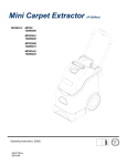
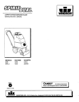
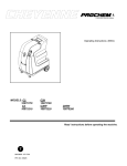
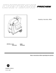
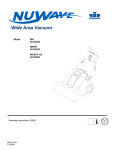
MINI-EXTRACTOR
Operating Instructions (GB/USA)
120V MODELS ONLY
E
86221950 04/27/07
PRV NO. 980238
Operating Instructions
MACHINE DATA LOG/OVERVIEW
MODEL _______________________________________
DATE OF PURCHASE __________________________
SERIAL NUMBER ______________________________
SALES REPRESENTATIVE # _____________________
DEALER NAME ________________________________
OPERATIONS GUIDE NUMBER ___________________
PUBLISHED
__________________________________________
YOUR DEALER
Name: _______________________________________________________________________________
Address: ____________________________________________________________________________
Phone Number: ______________________________________________________________________
2
86221950 02/20/07
TABLE OF CONTENTS
Machine Data Log/Overview................................2
Table of Contents.................................................3
HOW TO USE THIS MANUAL
How to use this Manual........................................1-1
SAFETY
GROUP PARTS LIST
Extractor Group. ...................................................... 5-1
Solution Pump Group. ............................................. 5-3
Wiring Diagram........................................................ 5-5
Hand Tool................................................................ 5-7
Mini Cart .................................................................. 5-9
Cart.......................................................................... 5-11
Suggested Spare Parts ........................................... 5-13
Important Safety Instructions ...............................2-1
Hazard Intensity Level..........................................2-2
Grounding Instructions. ........................................2-3
OPERATIONS
Machine Operations. ............................................3-1
Set Up and Operation ......................................3-1
Shut Down and Storage...................................3-1
MAINTENANCE
Maintenance Schedule.........................................4-1
Daily Maintenance.............................................4-1
Periodic Maintenance........................................4-1
Solution Pump Replacement................................4-1
Vacuum Motor Replacement. ..............................4-1
Carbon Brush Replacement..............................4-1
Machine Troubleshooting.....................................4-2
86221950 02/20/07
3
HOW TO USE THIS MANUAL
The PARTS LIST section contains assembled parts
illustrations and corresponding parts list. The parts
lists include a number of columns of information:
This manual contains the following sections:
-
-
HOW TO USE THIS MANUAL
SAFETY
OPERATIONS
MAINTENANCE
PARTS LIST
-
The HOW TO USE THIS MANUAL section will tell
you how to find important information for ordering
correct repair parts.
-
Parts may be ordered from authorized dealers.
When placing an order for parts, the machine model
and machine serial number are important. Refer to
the MACHINE DATA box which is filled out during the
installation of your machine. The MACHINE DATA
box is located on the inside of the front cover of this
manual.
-
MODEL _____________________________________
DATE OF PURCHASE ________________________
-
SERIAL NUMBER ____________________________
SALES REPRESENTATIVE # ___________________
DEALER NAME ______________________________
NOTE: If a service or option kit is installed on your
machine, be sure to keep the KIT INSTRUCTIONS
which came with the kit. It contains replacement parts
numbers needed for ordering future parts.
OPERATIONS GUIDE NUMBER __________________
PUBLISHED ________________________________
The model and serial number of your machine is on
the back underside of machine.
NOTE: The number on the lower left corner of the
front cover is the part number for this manual.
The SAFETY section contains important information
regarding hazard or unsafe practices of the machine.
Levels of hazards is identified that could result in
product or personal injury, or severe injury resulting
in death.
The OPERATIONS section is to familiarize the
operator with the operation and function of the
machine.
The MAINTENANCE section contains preventive
maintenance to keep the machine and its
components in good working condition.
1-1
REF – column refers to the reference
number on the parts illustration.
PART NO. – column lists the part
number for the part.
PRV NO. – reference number.
QTY – column lists the quantity of the
part used in that area of the machine.
DESCRIPTION – column is a brief
description of the part.
SERIAL NO. FROM – column indicates
the first machine the part number is
applicable to. When the machine design
has changed, this column will indicate
serial number of applicable machine. The
main illustration shows the most current
design of the machine. The boxed
illustrations show older designs. If
column has an asterisk (*), call
manufacturer for serial number.
NOTES – column for information not
noted by the other columns.
86221950 02/20/07
IMPORTANT SAFETY INSTRUCTIONS
When using an electrical appliance, basic precaution
must always be followed, including the following:
READ ALL INSTRUCTIONS BEFORE USING THIS MACHINE.
! WARNING:
To reduce the risk of fire, electric shock, or injury:
Use only indoors. Do not use outdoors or expose to rain.
Use only as described in this manual. Use only manufacturer’s recommended components and attachments.
If the machine is not working properly, has been dropped, damaged, left outdoors, or dropped into water, return
it to an authorized service center.
Do not operate the machine with any openings blocked. Keep openings free of debris that may reduce airflow.
This machine is not suitable for picking up hazardous dust.
Machine can cause a fire when operating near flammable vapors or materials. Do not operate this machine near
flammable fluids, dust or vapors.
During operation, attention shall be paid to other persons, especially children.
When leaving unattended, secure against unintentional movement.
The machine shall only be operated by instructed and authorized persons.
When leaving unattended, switch off or lock the main power switch to prevent unauthorized use.
Do not handle the plug or machine with wet hands.
Do not unplug machine by pulling on cord. To unplug, grasp the plug, not the cord.
Do not use with damaged cord or plug. Follow all instructions in this manual concerning grounding the machine.
Do not pull or carry by cord, use cord as a handle, close a door on cord, or pull cord around sharp edges or
corners.
Do not pull/run machine over cord. Keep cord away from heated surfaces.
Connect to a properly grounded outlet. See Grounding Instructions.
SAVE THESE INSTRUCTIONS
86221950 02/20/07
2-1
HAZARD INTENSITY LEVEL
The following symbols are used throughout this guide as indicated in their descriptions:
HAZARD INTENSITY LEVEL
There are three levels of hazard intensity identified by signal words -WARNING and CAUTION and FOR
SAFETY. The level of hazard intensity is determined by the following definitions:
! WARNING
WARNING - Hazards or unsafe practices which COULD result in severe personal injury or death.
! CAUTION
CAUTION - Hazards or unsafe practices which could result in minor personal injury or product or property
damage.
FOR SAFETY: To Identify actions which must be followed for safe operation of equipment.
Report machine damage or faulty operation immediately. Do not use the machine if it is not in proper operating
condition. Following is information that signals some potentially dangerous conditions to the operator or the
equipment. Read this information carefully. Know when these conditions can exist. Locate all safety devices on
the machine. Please take the necessary steps to train the machine operating personnel.
FOR SAFETY:
DO NOT OPERATE MACHINE:
Unless Trained and Authorized.
Unless Operation Guide is Read and understood.
In Flammable or Explosive areas.
In areas with possible falling objects.
WHEN SERVICING MACHINE:
Avoid moving parts. Do not wear loose clothing; jackets, shirts, or sleeves when working on the
machine. Use manufacturer approved replacement parts.
2-2
86221950 02/20/07
GROUNDING INSTRUCTIONS
THIS PRODUCT IS FOR COMMERCIAL USE
ONLY.
ELECTRICAL:
In the USA this machine operates on a standard 15
amp 115V, 60 hz, A.C. power circuit. The amp,
hertz, and voltage are listed on the data label found
on each machine. Using voltages above or below
those indicated on the data label will cause serious
damage to the motors.
EXTENSION CORDS:
If an extension cord is used, the wire size must be at
least one size larger than the power cord on the
machine, and must be limited to 50 feet (15.5m) in
length.
GROUNDING INSTRUCTIONS:
This appliance must be grounded. If it should
malfunction or break down, grounding provides a
path of least resistance for electric current to reduce
the risk of electric shock. This appliance is equipped
with a cord having an equipment-grounding
conductor and grounding plug. The plug must be
inserted into an appropriate outlet that is properly
installed and grounded in accordance with all local
codes and ordinances.
! WARNING
Improper connection of the equipmentgrounding conductor can result in a risk of
electric shock. Check with a qualified
electrician or service person if you are in
doubt as to whether the outlet is properly
grounded. Do not modify the plug provided
with the appliance - if it will not fit the outlet,
have a proper outlet installed by a qualified
electrician.
This appliance is for use on a nominal 120-volt
circuit, and has a grounded plug that looks like the
plug in “Fig. A”. A temporary adaptor that looks like
the adaptor in “Fig . C” may be used to connect this
plug to a 2-pole receptacle as shown in “Fig. B”, if a
properly grounded outlet is not available. The
temporary adaptor should be used only until a
properly grounded outlet (Fig. A) can be installed by
a qualified electrician. The green colored rigid ear,
lug, or the like extending from the adaptor must be
connected to a permanent ground such as a
properly grounded outlet box cover. Whenever the
adaptor is used, it must be held in place by a metal
screw.
86221950 02/20/07
2-3
MACHINE OPERATIONS
SET UP AND OPERATION
1. Upon removing your new mini-extractor from the
box, loosen the latch at back end of the machine
that secures the recovery tank to the solution
tank. Remove the recovery tank from the
solution tank.
2. Pour clean, hot water to the indicated fill line of
the solution tank. To avoid possible tank
distortion, water temperature must not
exceed 140 F (60C).
3. Add a non-foaming cleaning solution
concentrate, for use in hot water extractors at
the proportions noted on the container (See list
below), into solution tank.
4. Place the recovery tank back onto the solution
tank and refasten the latch.
5. Plug the power cord into grounded outlet (See
GROUNDING INSTRUCTIONS).
6. Connect the vacuum and cleaning tool hoses to
the extractor. This unit is equipped with an 1/8”
male quick connect for solution hose attachment
and a 1” ID vacuum hose hookup. Insure that
the female solution hose coupler is securely
locked onto the male coupler on the extractor.
7. Turn switch ON. This switch operates both the
vacuum motor and the water pump. NOTE: The
pump is an oscillating pump and should not be
run dry for extended periods of time. This may
cause damage to your pump, therefore voiding
your warranty.
8. Squeeze the solution lever on the cleaning tool
to spray cleaning solution and place the vacuum
head on the surface to be cleaned. Normally,
chemical is applied on the push stroke while
vacuuming is done on the pull stroke. For
heavily soiled carpets the hand tool may be
used in the scrubbing manner, applying
chemical in both the push and pull stroke.
ALWAYS FINISH UP AN AREA WITH A VACUUM PULL
STROKE.
9. When cleaning, be sure to monitor the level of
recovered solution in the recovery tank. When
the solution reaches the FULL mark, shut off the
extractor, loosen the latches and empty the
recovery tank.
NOTE: Dispose of waste in a proper manner
which would not violate any Local, State or
Federal law.
! CAUTION
Operating vacuum with solution above the FULL
mark could draw water directly into the vac motor.
This will cause damage to the motor, therefore
voiding your warranty.
! CAUTION
ALWAYS TEST UPHOLSTERY/CARPET FOR COLOR
FASTNESS IN AN INCONSPICUOUS PLACE. Also, to avoid
3-1
prolonged drying times, do not spray too much
solution in any one area.
! WARNING
Always use defoamer if foaming occurs. Foam
will suspend large particles which may damage
vacuum as well as allow liquid into the vacuum
motor without activating the float shutoff.
! WARNING
To prevent possible disease hazard, before
attempting to clean bodily fluids spills, you must kill
any viruses, germs or bacteria present in the bodily
fluid.
SUITABLE CHEMICALS INCOMPATIBLE CHEMICALS
Alkalis
Clorox II Bleach*
Defoaming Agents
Detergents
Hydroxides
Oxygen Bleaches
Soaps
Sta-Puf Fabric
Softener*
Vinegar
Aldehydes
Aromatic Hydrocarbons
Butyls
CarbonTetrachloride
Clorox*
Chlorinated Bleaches
Chlorinated Hydrocarbons
D-Limonene
Lysol*
Methyls (MEK)
Perchlorethylene perc)
Phenols
Trichlorethylene
*Registered Trademark
! WARNING
Before making any adjustments or performing any
maintenance to your machine, disconnect the power
cord from the electrical source.
SHUT DOWN AND STORAGE
1. Turn Switch OFF. Empty recovery tank
completely and rinse several times to remove
any dirt or debris that may be left behind.
2. Tip the solution tank over a sink to drain any
unused cleaning solution and rinse with clean
water to remove any suds left behind by the
cleaning chemicals. NOTE: Dispose of waste in
a proper manner which would not violate any
Local, State or Federal law
3. Run a small amount of clean water through
pump if chemicals were used. This will help
insure the life of your pump.
4. Check the spray jet on the cleaning tool for full
spray pattern and inspect vac head for any
obstructions. Also make sure to clean the filter
cap attached to portal cover of any debris that
may have been trapped during cleaning.
5. Remove as much moisture from system before
storing in cold climates. Excess water may
freeze during storage and crack internal
components, causing damage to the unit.
86221950 02/20/07
MAINTENANCE
DAILY MAINTENANCE:
Follow same procedure for Shut Down and Storage.
VACUUM MOTOR REPLACEMENT:
1. Turn off all switches and unplug machine.
PERIODIC MAINTENANCE:
1. Twice a month, flush a white vinegar solution
(one quart vinegar to two gallons water) or antibrowning solution (mixed as directed) through
the extractor. This will prevent build-up of
alkaline residue in the system.
2. If spray jet becomes clogged, remove the spray
tip, wash it thoroughly, and blow dry. NOTE: DO
NOT USE PINS, WIRE, ETC. TO CLEAN NOZZLE AS THIS
COULD DESTROY THE SPRAY PATTERN.
3. Apply silicone lubricant to solution nipple.
4. Periodically inspect all hoses, electrical cable
and connections on your machine. Frayed or
cracked hoses should be repaired or replaced to
eliminate vacuum or solution pressure loss. If
the cable insulation on the power cord is broken
or frayed, repair or replace immediately. Don’t
take chances with electrical fire or shock.
2. Unlatch and remove recovery tank.
Only qualified maintenance personnel are to perform
the following repairs.
SOLUTION PUMP REPLACEMENT:
3. Unfasten screws holding vacuum motor retainer
to vacuum motor housing
4. Lift vacuum motor from vacuum motor housing.
Locate the vacuum motor wires and disconnect
at the connector.
5. Remove vacuum motor.
6. Reverse process to install vacuum motor
replacement.
Vacuum Motor Carbon Brushes Replacement
End Cap
Carbon
Brushes
WARNING: The green
ground wire must be
attached for safe operation.
See wiring diagram.
If armature commutator is grooved, extremely pitted or not
concentric, the motor will need to be replaced or sent to a
qualified service center.
1. Turn off all switches and unplug the machine.
2. Unlatch and remove recovery tank.
3. Unfasten screws holding vacuum motor housing
to solution tank.
4. Unfasten screws holding pump plate to bottom
of solution tank.
Important:
These brushes wear quicker as the length shortens due to
increased heat. Spring inside brush housing will damage
motor if brushes are allowed to wear away completely.
5. Remove solution hoses from fittings on pump.
6. Remove pump from brackets and remove fittings
and grounding wire.
7. Reverse process to install new replacement
pump.
3 [9.5mm]
8
Periodically check the length of the carbon brushes. Replace
both carbon brushes when either is less than 3/8" (9.5mm)
long.
86221950 02/20/07
4-1
TROUBLESHOOTING
TROUBLESHOOTING
PROBLEM.
Little or no solution flow
CAUSE
SOLUTION
Clogged spray jet on
cleaning tool
Remove and clean jets
Check and replace pump.
Faulty pump
Loss of vacuum/
Solution recovery
4-2
Incorrectly attached
solution hose
Incorrectly attached vac
hose
Obstruction in cleaning
tool
Recovery tank is not
securely mounted on the
solution tank.
Ensure solution hose coupler is securely attached to
the coupler on the solution tank.
Ensure vac hose is pushed completely onto the
recovery tank inlet.
Inspect for and remove any debris.
Tighten latch on either end of the machine.
86221950 02/20/07
NOTES
86221950 04/27/07
4-3
EXTRACTOR GROUP
13
48
15
14
86226140
PRV NO. 880434 (REF)
86226130
PRV NO. 880433 (REF)
1
2
230V MODELS ONLY
47
PART OF ITEM 16
3
11
4
8
9
10
12A
12B
21
5
8
9
6
7A
7B
8
9
17
22
23
27
19
18
39
20
25
24
26
86226310
PRV NO. 88884 (REF)
28
PART OF
ITEM 40
45
44
TO
PUMP
8
27
29
38
30A
30B
37
41
16A
16B
16C
16D
45
46
31
43
42
40
32
MOUNTING
SURFACE
DETAIL 'A'
33
SEE DETAIL 'A' FOR INTERNAL
SOLUTION TANK PARTS
34
35
36
5-1
86221950 04/27/07
EXTRACTOR GROUP
REF PART NO. PRV NO. QTY DESCRIPTION
1
2
3
4
5
6
7A
7B
8
9
10
11
12A
12B
13
14
15
16A
16B
16C
16D
17
18
19
20
21
22
23
24
25
26
27
28
29
30A
30B
31
32
33
34
35
36
37
38
39
40
41
42
43
44
45
46
47
48
86225200
86236520
86223730
86237440
86223440
86217310
86258440
86225500
86274290
86225770
86237410
86237420
86215670
86215710
86010690
86261160
86136540
86217060
86217040
86217070
86217080
86136550
86079650
86275870
86225760
86002010
86233510
86225110
86219310
86237460
86237450
86010640
86218030
86068560
86225190
86225220
86246180
86006520
86218160
86247740
86227220
86200820
86197580
86197370
86288450
86258310
86279320
86248090
86007700
86219010
86233150
86220140
86241790
86236010
75211
34293
70859
35168
67511
270102
53137
53813
70162
87494
35160
35161
140839
141046
87068
27952
67481
23722
23720
23723
23724
67483
62129
70556
87493
14942
27376
72194
41278
35173
35172
87016
35354
140037
75210
75459
51320
70052
35368
56049
04066
270-11A
40029
31017
70689
140070
87136
59034
73250
39708
20042
500895
48074
34290
1
1
2
1
1
1
1
1
6
4
1
1
1
1
2
1
3
1
1
1
1
2
1
2
2
1
1
1
1
1
2
3
1
1
1
1
2
4
1
1
1
1
1
1
1
1
2
1
1
1
2
1
2
1
TANK, RECOVERY
FOAM, 4.00 OD X 1.0 THICK
SCREW, 8-32 X 1/2 FHMS BLK PLTD
GASKET, 4.06 X 2.50 X .38
RETAINER, VAC MOTOR
COVER, VAC MOTOR
VAC MOTOR, 120V 2ST LNP
VAC MOTOR, 230V 2ST LNP
SCR, 10-32 X 3/8 PPHMS SS
WASHER, M6 X 12.5 FLAT SS
GASKET, SPOTTER RECOVERY
GASKET, 4.0 X 5.5” X .25 PORON
BREAKER, 8A VDE CIRCUIT
BREAKER, 5A VDE CIRCUIT
WASHER, 1/8 RIVET BACKUP
CAPACITOR ASM, EMI SPOTTER
RIVET, M4 X 14 MM
CORD ASM, 14 X 3 25’ YLW SPOTTER
CORD ASM, UK SPOTTER
CORD ASM, EURO SPOTTER
CORD ASM, AUST SPOTTER
RIVET, M3 X 12 MM
PLATE, DATA LABEL
SCREW, 1/4-20 X 1.5 PHMS PLTD
WASHER, M8 X 22 FLAT PLTD
BOOT, 3/8 CIRCUIT BREAKER
CLIP, SWITCH RETAINING
SWITCH, DPST 250V 16(4) SPLASH
HOUSING, VAC
GASKET, .31 x .75 x 1.98
GASKET, VAC HOUSING 3/16”
WASHER, #10 EXT. TOOTH LOCK
GASKET, VAC HOUSING 3/8”
BRACKET, NIPPLE
TANK, SOLUTION
TANK, SOLUTION SPOTTER GRAY
LATCH, PRESTO TANK
SCREW, 8-32 X 3/8 PPHMS SS
GASKET, GROUND WIRE
NIPPLE, 1/4 X 6.0 BRASS
ADPTR, 1/8 MPT X 1/4 FPT BRASS
NIPPLE, 1/8 FPT QD MALE BRASS
HOSEBARB, 1/4 MPT X 3/8
ELBOW, 1/4 FPT X 1/4 FPT
SCR, M4.8 X 10 HHTF TYPE B
BULKHEAD, UNION
WASHER, .52 ID X .875 OD
O-RING, .500 ID X .688 OD X .103
STRAINER, 80 MESH X 3/8 FPT
HOSE, 3/8 ID SGLBRD RBR X 5”
CLAMP, HOSE
LABEL, WARNING
KEEPER, PRESTO LATCH
FILTER, EMI 250V 6A 1.75MM
SERIAL NO.
FROM
NOTES:
230V MACHINES ONLY
230V MACHINES ONLY
U.S. MACHINE
UK MACHINE
EUROPE MACHINE
AUSTRALIA MACHINE
230V MACHINES ONLY
86221950 04/27/07
5-2
SOLUTION PUMP GROUP
1
9
5
6
2
5
3
4
4
7A
7B
3
5
8
5-3
86221950 02/20/07
SOLUTION PUMP GROUP
REF
PART NO.
PRV NO.
QTY
DESCRIPTION
1
86275710
70528
2
2
3
4
5
86068690
86237530
86197590
86233150
140172
35187
40031
20042
1
3
2
3
6
86240290
39714
1
7A
86201110
250-78
1
SCREW, 10-32 X 3/8 PPH EXSEMS
BRACKET, SOLENOID PUMP
GASKET, TUBE SEAL
HOSEBARB, 1/8 MPT 3/8 90°
CLAMP, HOSE
HOSE, 3/8ID WIREBOUND X
2.6”
PUMP, 110/120V 60HZ FLOJET
7B
86201120
250-78A
1
PUMP, 220/240V 50 HZ FLOJET
8
86281310
39326
1
9
86010640
87016
2
SERIAL NO.
FROM
NOTES:
230V MACHINES
ONLY
HOSE, 3/8ID WIREBOUND X
8.8”
WASHER, #10 EXT. TOOTH
LOCK
86221950 02/20/07
5-4
WIRING DIAGRAM
CIRCUIT BREAKER
BLK
WHT
BLK
WHT
GRN
4
1
SWITCH
BLK
VAC
BLK
1
9
10
GRN
2
BLK
WHT
PUMP
3
120V MACHINES
CAPACITOR
CIRCUIT BREAKER
LOAD
FILTER
LINE
8
BLU
GRN
BLK
WHT
BLK
BRN
GRN
7
5
6
SWITCH
1
BLK
VAC
BLK
1
GRN
9
10
BLK
PUMP
230V MACHINES
5-5
86221950 02/20/07
2
WHT
3
WIRING PARTS LIST
REF
PART NO.
PRV NO.
QTY
1
2
3
4
5
6
7
8
9
10
86226310
86226100
86226110
86226120
86226130
86226140
86226160
86226150
86006770
86010640
88884
880430
880431
880432
880433
880434
880436
880435
70323
87016
2
1
1
1
1
1
1
1
1
1
DESCRIPTION
SERIAL NO.
FROM
NOTES:
WIRE, 14” GRN/18 76008 X 76008
WIRE, 13” BLK/14 76050 X 76029
WIRE, 13” WHT/14 76050 X 76059
WIRE, 9” BLK/14 76029 X 76029
WIRE, 9” BLK/14 76050 X 76029
WIRE, 9” WHT/14 76050 X 76029
WIRE, 10” GRN/14 76022 X 76010
WIRE, 12” BLK/14 76029 X 76022
SCR, 10-32 X 1/4 PHTR PLTD
WASHER, #10 LOCK EXT STAR SS
86221950 02/20/07
5-6
HAND TOOL
1
3
2
5
6
7
8
4
5-7
86221950 02/20/07
HAND TOOL
REF
PART NO.
PRV NO.
1
86219340
41536
2
3
4
5
86225670
86219020
86200810
86219570
84200
39712
270-11
44100
6
86223100
629998
7
8
86221910
86218000
54202
34438
-
86218790
HTO
DESCRIPTION
SERIAL NO.
FROM
NOTES:
HOUSING, HANDTOOL
SPOTTER OKA
VALVE ASM, SPOTTER OKA
HOSE ASM, VAC/SOLUTION OKA
NIPPLE, 1/8 FPT QD FEM BRASS
JET, ASM W/O RING OKA
PLATE, RETAINER
W/HARDWARE OKA
MANIFOLD, SPOTTER OKA
FTTG, 1/8MPT X 3/16 COMP OKA
HAND TOOL, SPOTTER OKA
86221950 02/20/07
ENTIRE ASSEMBLY AS
KIT
5-8
MINI CART
1
2
3
4
5-9
86221950 02/20/07
MINI CART
REF
PART NO.
1
2
3
4
86222950
86259770
86137280
86136640
86222030
-
PRV NO. DESCRIPTION
62846
89086
87054
70262
PMCT
PLATE, WELDMENT
WHEEL, 5”D X 1” X .5” ID GRY
WASHER, M8 FLAT DIN125A PLT
SCR, M8 X 20 HHMS PLTD
MINI CART
86221950 02/20/07
SERIAL NO.
NOTES:
FROM
ENTIRE ASSEMBLY AS KIT
5-10
CART
5-11
86221950 02/20/07
CART
REF
PART NO.
PRV NO.
1
2
3
4
5
6
7
8
9
10
11
-
86089270
86273740
86271380
86005700
86259970
86005680
86092130
86006590
86228340
86232530
86010630
86000030
78310
70010
57196
57104
89507
57047
27637
70088
140088
18010
87013
PCT
DESCRIPTION
TUBE, CART HANDLE
SCREW, 1/4-20 X 1.5 TAP PLTD.
NUT, 1/2 STAR LOCK PUSH-ON
NUT, 10-32 HEX W/ STAR WASHER
WHEEL, 8” GREY
NUT, 1/4-20 LOCK
CART BASE ASM, SPOTTER
SCREW, 10-32 X 1/2 PPHMS SS NP
BASKET, CART
CASTER, 2.5 DIA
WASHER, 1/4 ID X 5/8 OD SS
SPOTTER CART
86221950 02/20/07
SERIAL NO.
FROM
NOTES:
ENTIRE ASM AS KIT
5-12
SUGGESTED SPARE PARTS
REF
PART NO.
PRV NO.
DESCRIPTION
1
2
3
4
5
6
7
86225110
86258440
86225500
86201110
86201120
86135320
86135330
72194
53137
53813
250-78
250-78A
140687
140688
SWITCH, DPST 250V 16(4) SPLASH
VAC MOTOR, 120V 2ST LNP
VAC MOTOR, 230V 2ST LNP
PUMP, 110/120 60HZ FLOJET
PUMP, 220/240V 50HZ FLOJET
BRUSH SET, 120V VAC, WINDSOR
BRUSH SET, 230V VAC, WINDSOR
5-13
86221950 02/20/07
SERIAL NO.
FROM
NOTES:
120V MOTOR ONLY
230V MOTOR ONLY