1
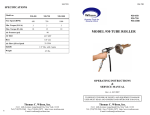
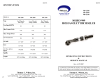
SM-97 SPECIFICATIONS Model no. 3A-450 38640-0450 3A-750 38640-0750 3A-1000 38640-1000 450 750 1000 Min. Torque Ft-Lb 3 3 3 Max. Torque Ft-Lb 18 12 10 Free Speed (RPM) Air Pressure psi 90 Air Inlet 3/8” NPT Hose 3/8” I.D. Air Flow @Free Speed 32 CFM Spindle SM-97 Torq-Air-Matic ڤModel 3A-450 (450RPM) ڤModel 3A-750 (750RPM) ڤModel 3A-1000 (1000RPM) 1/2” Dia. with 2 spots OPERATING INSTRUCTIONS & SERVICE MANUAL TO REDUCE THE RISK OF INJURY, USER MUST READ AND UNDERSTAND OPERATOR’S MANUAL. 16 Thomas C. Wilson, Inc. Thomas C. Wilson, Inc. 21-11 44th Avenue, Long Island City, New York 11101 Tel: (718)729-3360 Fax: (718)361-2872 http://www.tcwilson.com Email: [email protected] 21-11 44th Avenue, Long Island City, New York 11101 Tel: (718)729-3360 Fax: (718)361-2872 http://www.tcwilson.com Email: [email protected] SAFETY INSTRUCTIONS ! SM-97 WARNING! READ AND UNDERSTAND ALL INSTRUCTIONS Failure to follow all instructions listed below, may result in accident, fire and/or personal injury. SAVE THESE INSTRUCTIONS 1. Do not allow corrosive gases or foreign material to enter the unit. Moisture, oil-based contaminants, or other liquids must be filtered out. 2. Eye protection is always required when running motor. 3. Hearing protection is recommended when in close proximity to all operating air motors. 4. Dust mask, non-skid safety shoes, hard hat, gloves and other personal safety equipment must be used. 5. Stay alert, watch what you are doing, and use common sense when operating a power tool. 6. Dress properly. Do not wear loose clothing or jewelry. 7. Keep your work area clean and well lit. 8. Do not operate power tools in explosive atmospheres, such as in the presence of flammable liquids, gases, or dust. 9. Disconnect the tool from the air supply before installing, making any adjustment, changing accessories, servicing or storing tool. 2 TROUBLE-SHOOTING (Cont’) PROBLEM SM-97 CAUSE & SOLUTION Torque control will 1. Broken latch release pawl not release at torque —Replace–see pg. 8, (Pc. #36, pg. 11). setting 2. Broken torque spring —Replace–see pg. 8, (Pc. #5, pg. 11). 3. Broken latch —Replace–see pg. 8, (Pc. #34, pg. 11). 4. Broken or excessive wear on tips of all pawls —Replace-see pg8(Pc29,36,40&42, pg.11). 5. Broken spring ends or anchor pins of latch pawls and reverse pawl —Replace–see pg.8, (Springs & pins, pg. 11). 6. Reaction member seized to int. gear assembly —Consult factory 7. Broken or short roll pin stop on reaction member. Check for scoring on stop plate section of handle connector —Replace–see pg. 7, (Pc. #32, pg. 11). 8. Ball retainer has broken or lost any balls. Check correct assembly of retainers. —Replace–see pg. 9, (Pc. #43, pg. 11). Torque control will not relatch in reverse 1. Broken latch or latch spring —Replace–see pg. 8, (Pc. #28,34, pg. 11). 2. Broken reverse pawls, springs or anchor pin —Replace–see pg.8 (Pc#39,40,41,42, pg.11). 3. Slot radii on internal gear oversized/gouged —Replace internal gear (Pc. #10, pg. 11) 4. Insufficient torque on drive spindle end —See note on pg.5. Hold spindle end in vise and manually turn TAM ccw; should relatch. 5. Excessive burrs or wear on internal gears preventing free rotation —Debur/replace–see pg. 7,(Pc. #10, pg. 11). Caution: Disassembly or reassembly of torque control unit must be performed by qualified personnel. It is advisable to return torque control units to the factory or consult the factory for necessary repair. 15 SM-97 TROUBLE-SHOOTING PROBLEM CAUSE & REMEDY Motor will not run. 1. Inefficient air supply —Check 90 psi and 32 CFM air supply. 2. Clogged air inlet screen —Replace-see pg.6(pc #75, pg.13). 3. Broken or severely worn rotor blades —Replace-see pg.6(pc #69, pg.13). 4. Rust due to improper storage of tool —Disassemble and clean– Refer to Disassembly procedure. 5. Broken throttle valve pin or lever —Replace–see pg.6(pc. #78/80, pg. 13). Motor will not reach RPM. 1. Insufficient air volume —Check 32 CFM supply. 2. Dirty air inlet screen —Clean –see pg. 6 (pc.#75, pg.13). 3. Worn rotor blades —Replace-see pg.6(pc #69, pg.13). 4. Air supply hose chocked or too small —See Operating Procedure recommended hose. Motor stalls at high torque Motor fails to stop 14 1. Insufficient air pressure —Check 90 psi supply 2. Dirty air inlet screen —Clean –see pg. 6 (pc.#75, pg.13). 3. Rotor blades worn, chipped or broken —Replace-see pg.6(pc #69, pg.13). 1. Broken throttle valve spring —Replace-see pg.6(pc #76, pg.13). 2. Valve ball does not seal —Replace or rework valve seat-Refer to pg. 6 (pc.#77, pg.13) GUIDELINES FOR TUBE EXPANSION SM-97 Improperly rolled joints create additional expense to correct, whether they are under-rolled and can be corrected merely by rerolling, or over-rolled and require removal and replacement. The optimal joint is one that develops a leak tight joint with adequate strength for the service intended with the minimum amount of cold working or reduction of the tube wall. Experience indicates that joints of this type are obtainable with non-ferrous tubes in surface condensers by expanding to a wall reduction of 3% to 4% after metal to metal contact of the tube 0.D. with the tube sheet hole. Steel tubes in heat exchangers may require wall reductions of 5% to 10%; soft copper and aluminum tubes in heat exchangers also require larger wall reductions in the area of 8% to 12%. Boiler tubes requiring development of optimum joint strength require wall reductions of 12% to 14%. A typical example of the application of this method is indicated for a 3/4” x 18 ga. tube in a condenser. Tube Expansion Calculations Tube Sheet Hole Dia. - Tube O.D. = Clearance + Tube I.D. =I.D. @ Metal to Metal +4%Reduction (.049x.04x2) =Expanded I.D. .760 -.750 =.010 +.652 =.662 +.004 =.666 OPERATION RECOMMENDED OPERATING AIR PRESSURE 90 PSI 1. Make sure there is an adequate supply of clean air of 90 psi lubricated with light machine oil of SAE 10 viscosity. This should be done before all long runs of tube expanding and after every four hours of continuous use unless an air line lubricator of ample capacity is used. SEE ’LUBRICATION’ SECTION BELOW. 3 OPERATION (Cont’) SM-97 PARTS LIST (Cont’) SM-97 2. Loosen the four hexagon socket set screws at rear of control housing 1/2 to 3/4 turn and rotate index mark on housing to desired torque. Tighten all four screws. See paragraph entitled “Calculating the Expansion Required”. To avoid the possibility of over-rolling, it is best to make the trial setting low and work up to the desired setting, a record of which should be kept for future use. 3. The clamp-on handle (Part No. 24305) can be swiveled to the position most convenient for the operator. Its use is optional but recommended for any job requiring more than three footpounds torque. 4. Always blow out air hose thoroughly before attaching it to throttle valve cap which takes the 3/8” pipe coupling of 3/8” hose assembly supplied (No. 50007). Always use a 3/8” I.D. or larger air line when maximum power is desired and be sure that air pressure at the tool is at least 90 psi gauge. 5. The exhaust deflector can be rotated to deflect exhaust air in the most convenient direction. 6. Select required snap-on mandrel drive and attach it to tool spindle nose. Be sure to align detents within it with drilled spots on spindle nose. (Instructions for releasing detents are stamped on mandrel drive sleeves.) 7. Adjust Thrust Collar on expander and attach mandrel to snap-on mandrel drive by engag-ing detent and circular groove on mandrel’s square shank. 4 13 SM-97 PARTS LIST (Cont’) Key Description 3A1000 3A750 3A450 Motor & Spindle Assembly 38649 38649 38649 -1000 -0750 -0450 Intermed Spindle Ass’y (Keys 55 thru 61) 51143 51142 51141 OPERATION (Cont’) SM-97 Key Description 3A1000 3A0750 3A0450 8. 77 Valve Ball 2629 2629 2629 78 Valve Pin 51540 51540 51540 79 Lever Pin 28215 28215 28215 9. Completely depress throttle valve trigger lever to find forward speed. When preset torque has been reached, drive will dis-engage and mandrel will stop rotating; release throttle valve lever when this occurs. Throttle Valve Lever 53501 53501 53501 Insert expander in tube as required. 55 Intermediate Spindle 51123 51122 51121 80 56 Planet Pin (2) 24512 24512 24512 82 Trigger Pin 28215 28215 28215 57 Planet Gear (2) 51102 24321 51105 84 Throttle Valve trigger 51563 51563 51563 85 Reversing Valve Trigger 51544 51544 51544 86 Trigger Spring 52635 52635 52635 Note: There must be a positive resistance to turning on the tool 87 Drive Screw (2) 6896 88 Nameplate 38635 38635 38635 spindle of 5-6 inch— pounds in the reverse direction before drive will reengage and set latching pawls for rotation in the forward direction. 89 Retaining Ring 53560 53560 53560 90 Gasket 51229 51229 51229 91 Rear Plug 21994 21994 21994 92 Rear Motor Bearing 21944 21944 21944 93 Rear End Plate 51532 51532 51532 94 Roll Pin 51474 51474 51474 95 Seal Ring 28187 28187 28187 96 Exhaust Muffler Assy 53840 53840 53840 Dead Handle 24305 Hex. Key 5/16 52147 Hex. Key 1/8 52144 Hex. Key 3/16 51254 58 Needle Roller (2 Sets) 24354 24354 24354 59 Roller retainer (2 Sets) 24355 24355 24355 60 Retainer Washer 51118 51118 51118 61 Rear Drive Ball Bearing 24525 24525 24525 Air Motor Assembly (Keys 62 thru 69) 53581 53581 53581 -0001 -0002 -0003 62 Rotor 51133 51132 51131 63 Adapter Ring 52497 52497 52497 64 Bearing Separator 51191 51191 51191 65 Front Motor Bearing 51361 51361 51361 66 Front Plate 50809 50809 50809 67 Front Bearing Spacer 51135 51135 51135 68 Cylinder 51225 51225 51225 69 Rotor Blade (Set of 4) 51139 51139 51139 Motor Housing Ass’y Key70thru86,90,93&94 53579 53579 53579 70 Motor Housing 53580 53580 53580 74 Throttle Valve Cap 42872 42872 42872 75 Air Screen 51179 51179 51179 76 Throttle Valve Spring 51541 51541 51541 6896 6896 10.Fully squeeze reverse valve trigger into reverse position (depressed). Valve locks in this position and only releases when throttle valve trigger lever is released. Depress throttle valve trigger lever to reverse drive and back expander out of tube. 11. Measure tube’s actual inside diameter. If the amount of expansion is not sufficient, adjust torque control to a slightly higher value and roll the next tube. 12. When desired expansion has been attained, maintain the setting and roll the entire lot. Reroll all trial tubes which were not completely expanded. 13. Always record settings used and tube data such as tube 0.D. and gauge with tube sheet thickness for future reference. LUBRICATION Amount of oil used will vary with tool usage but daily filling of handle oil reservoir should normally be adequate. Check that a fine mist of oil is always present in the air which passes out through exhaust deflector holes. For continuous and heavy tool usage, it is preferable to use an automatic air line lubri-cator. For this purpose, the Wilson Air Filter-Lubricator Unit (Cat. #8596 for 3/8” lines) is recommended. This unit combines an automatic lubricator with an efficient air filter. Caution: To inhibit rust during tool storage be sure a liberal amount of oil has been introduced into valve and air motor. Also be sure operat-ing air moisture content is kept at a minimum. Compressor after coolers, air line traps, water separators and use of rust-inhibiting lubricat-ing oil all help. Thoroughly clean or replace any rusted parts found during service checks. 12 5 MAINTENANCE & SERVICING SM-97 SM-97 PARTS LIST (Cont’) Air Tools should be handled with reasonable care when servicing. It is important that the correct tools and fixtures are used when servicing this Air Tool. Order replacement parts by part number, model and serial number of tool. To maintain Torq-AirMatic efficiency, periodic checks should be made of the following: Rotor Blades - Generally these are the only parts requiring replacement after long service. Always replace the rotor blades in a set of 4 only, whenever they are broken or cylinder edge is gouged, worn uneven or worn down 1/16". This would cause the blade edges to be 1/16" below top of its slot in rotor drum. Cylinder and Rear End Plate - Replacement is required only if part is broken or rubbing surfaces are gouged. Ball Bearing - normally these ball bearings should not require additional lubrication during tool life. However, whenever tube roller is disassembled for servicing, the motor ball bearings should be lubricated with light oil (SAE #10) while the drive ball bearings should receive a small amount of bearing grease. All ball bearings should turn smoothly and freely with no noticeable looseness. There should be a snub fit with no shake both in their housings and on their shafts. However, the front motor ball bearing is a mild press fit on its rotor shaft. Note: Dirty or gummed up ball bearings should be cleaned in kerosene and flushed with clean light oil (SAE No. 10). DO NOT USE AN AIR BLAST. After flushing, re-lubricate as specified. Be sure both plastic seals are properly replaced on front drive ball bearing. 50 Intermediate Spindle Assembly and Drive Spindle Assembly - Do not disassemble planet gears from their spindles unless the gears do not move freely about their planet pins. Be careful not to lose any one of the nine needle rollers assembled within each planet gear. Lubricate planet gear and needle rollers with a good bearing grease only. Caution: Note position of planet pin milled step in relation to steel retaining ring or turned step on drive spindle on assembly drawing before reassembling either spindle. Air Screen - Throttle valve air screen assembly should be cleaned by reverse flushing when necessary. Before reassembly note on drawing that air screen cylinder is assembled within the throttle valve cap. Also when reassembling be sure small end of conical throttle valve spring rests against the 3/8" diameter hardened steel ball. Be sure air screen flange comes to rest correctly within its counter-bore in steel seat insert. 6 11 SM-97 PARTS LIST Key Description Torque Control Ass’y 3A1000 3A750 3A450 38641 38641 38641 -1000 -0750 -0450 1 Retainer (2) 24317 2 Spirolox Ring 34262 3 Front Bearing 28069 4 Control Housing Ass’y 5 6 Key Description 3A1000 3A0750 24907 27 Retainer 28096 28 Latch Spring 24913 Torque control disassembly procedure 29 Latch Return Pawl 24911 If air motor has been operating properly, do not remove it from torque control section at this time, but proceed as outlined. The steps to be followed have been grouped. Steps within a group may be performed in any sequence. The groups, however, cannot and must not be per-formed out of sequence. All steps within a group must be completed before proceeding to the following group. Refer to assembly drawing on Page 11. 30 Return Pawl Spring 24912 31 Latch Pin 24333 Main Spring 24307 32 Roll Pin (2) 25177 Main Spring Anchor 24318 33 Roll Pin 24908 Latch 24910 7 Button Head Screw (2) 24319 8 Lock Washer (2) 28106 35 Latch Release Spring 24331 24313 36 Latch Release Pawl 24323 9 Main Spring Pin 10 Internal Gear 38658 38657 38658 37 Latch Release Pin (2) 24330 11 Drive Spindle 38664 38664 38661 38 Dowel Pin 24298 24504 24364 24321 39 Reverse Pawl Pin 24328 Tongued ReversePawl 38665 38665 13 Needle Roller (3 Sets) 24354 40 14 Roller Retainer (3Sets) 24355 41 Reverse Pawl Spring 24914 15 Planet Pin (3) 24314 42 Grooved ReversePawl 24909 16 Snubber Shim (0-3) 40561 43 Retainer Set Screw (4) 17 O-Ring 28100 18 Quad-Ring 28102 45 Index Plate 19 O-Ring 28101 46 Screw (2) 24320 Rear Bearing 51194 38651 20 Quad-Ring 28103 47 21 Brake Shoe 38643 48 Handle Connector 22 Brake Rolls Retainer 24311 49 Internal Gear 50 Balls (13) Brake Roll (3) 24324 24 Bearing Race BrakeCam 38644 25 Front Ball Retainer 28088 Group no.1 (A) Unscrew and remove both spring anchor button head screws. Use 3/16” hexagon key supplied. (B) (B) Unscrew all four torque setting set screws halfway out at rear of control housing. Use 1/8” hexagon key supplied. (C) Remove outside bearing shaft retainer ring (Piece No.1). 38665 28067-0001 44 23 The following instructions should be studied carefully before attempting disassembly of Model ‘3A’ Torq-Air—Matic. In most cases, the major difficulty encountered has been caused by improper disassembly and reassembly procedures. Reaction Member 40024 40024 40024 -1000 -0750 -0450 Planet Gear (3) SM-97 26 34 12 3A0450 DISASSEMBLY 20480 38653 40014 38652 38654 38653 38655 Group no. 2 (A) Grasp unit by torque control housing with the 1/2” diameter output spindle uppermost and vertical. Hold it with the motor handle 1/2’ to 1” above the work surface. (B) With a soft faced hammer, tap the output spindle gently. The entire internal mech-anism will fall free as soon as the reduced diameter portion of output spindle has pass-ed through front ball bearing. NOTE: Avoid hitting this bearing or housing. Group no.3 (A) (B) (C) (D) (E) Remove inside bearing shaft retainer ring (Pc #1). Lift out front ball bearing (Pc #25). Lift off front brake shoe (Pc #21 ). Remove 3 brake rolls (Pc #23). Lift off brake roll retaining ring (Pc #22 ). 21941 Group no.4 (A) The subassembly consisting of reaction member assembly with latch and various pawls, mainspring with its pin and anchor and brake cam may then be lifted up off motor drive spindle assembly. (B) When failure is due to a malfunction of torque control unit, the failing parts, usually, can be found easily by observing operations of the various pawis and latch. This can be done by holding subassembly in the hand and applying torque or turning force to internal gear (Pc #10) within reaction member (Pc #26). See Trouble Shooting Chart. 10 7 DISASSEMBLY(Cont’) SM-97 REASSEMBLY SM-97 NOTE: As machine is being driven in forward direction, a counterclockwise torque is applied to the internal gear, when looking at the open end. This gear is prevented from turning in reaction member by the latch (Pc. #34), which can be released by tripping release pawl (Pc #36) while applying a counterclockwise torque to internal gear, which is then free to continue rotation in that direction. When tool is reversed, a clockwise torque is applied to internal gear which makes one turn only to reengage the main latch (Pc #34). To reassemble TORQUE CONTROL or AIR MOTOR follow disassembly steps in reverse. Group no. 5 • Air motor special note Be sure rotor blades are well oiled before replacing them in their rotor slots. Also check that rotor turns very freely after air motor is reassembled and adapter ring is tightened down. Observe extreme care in mesh-ing the rotor pinion and intermediate spindle pinion with their planet gears when reassembling gear housing assembly to air motor. If investigation shows that malfunction is due to a broken latch, pawl or spring, they can be replaced in the following manner: (A) Grasp brake cam (Pc #24) and punch reaction member from it. NOTE: When replacing this brake cam for reassembly, be sure it is seated squarely and firmly against the shoulder on the reaction member. Group no.6 (A) Mainspring (Pc #5) with its anchor (Piece No.6 ) and mainspring pin (Pc #9)can then be removed. Group no.7 (A) Removal of retaining ring (Pc #27) will permit removal of various pins on which the latch and pawls are pivoted. consisting of reaction with latch and various pawls, its pin and anchor and brake lifted up off motor drive Air motor disassembly procedure (A) Hold Torq-Air-Matic fixed with offset handle upwards. (B) Prevent rotation with wrench locked on 2” hexagon located against torque calibrated index plate. (C) Tap motor handle with a soft-faced mallet in a counterclockwise direction when viewed from offset handle end. (D) Unscrew and remove air motor and offset housing assembly complete. (E) Remove intermediate spindle assembly from air motor assembly or from within internal gear. (F) Unscrew adapter ring (Pc #63 ) out of cast aluminum motor housing. (G) Rotor with 4 rotor blades, front plate spacer, ball bearing and separator can now be lifted out. Note: Leave cylinder and assembled rear end plate within motor housing. Refer to assembly drawing on page xx. 8 • Torque control special note On reassembly of ball retainers, small ball retainer (Pc #25) must be assembled with solid part of ball cage facing steel front bearing housing (Pc #4) in aluminum control housing. Large ball retainer (Pc #43) must be assembled with solid part of ball cage facing steel handle connector (Pc #48). • Complete torq-air-matic reassembly sequence Assemble air motor into motor housing, then assemble intermediate spindle assembly to air motor assembly. Next screw intermediate internal gear with attached torque control assembly onto adapter ring. Tighten air motor assembly to torque control assembly. See method of disassembly above. Assure that gears mesh properly before tightening; do not force. Torque unit will screw onto motor assembly easily with proper gear mesh. Maintenance and Repair tools 4 Oz. Ball Pein Hammer 4 Oz. Soft Faced Hammer (Brass and Plastic Tip) Set of Screwdrivers:1/8” w. x 4” 1g. blade 1/4” w. x 4” 1g. blade 9” Smooth Jaw Adjustable Wrench (With 2” Minimum Opening) 8” Pressure Lock Wrench (vise grip) Set of Allen Hex. Wrenches (5/64, 3/32, 1/8, 5/32 and 3/16) 9-1/2” Channel Lock Pliers Long Needle Nose Pliers Set of Retaining Ring Pliers Waldes No. 2 & No. 4 Set of Machinists long nose punches (1/16, 3/32, 1/8, 5/32, 3/16 and 1/4) 6-1/2” Half Round Needle File for Deburring Small Hand Scraper for Deburring Sheets fine emery cloth for polishing 9