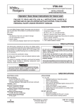
Transcript
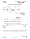
CONFIGURATION AND
TYPICAL WIRING DIAGRAMS
1F80-224 / 1F80-240 / 1F80-241/1F80-361
1F86-241 / 1F86-344 / 1F87-361
CONFIGURATION
1F86-241
Step
Step
1
N/A
N/A
1
PRGM
and RUN
N/A
1
1
N/A
Set SYSTEM
switch to OFF
2
2
2
HOLD*
*
1
1
1
N/A N/A N/A
2
1F86-344
1F80-361
Step Step Step
1F87-361
Step Press Button(s)
1F80-224
1F80-241
*1F80-240
The following table allows you to customize the options on your Comfort-Set thermostat.
Configuration Menu
Displayed
(Factory Default)
Press Button(s)
HOLD
(0:00)
Press
or
to select:
0 to 8 hrs (in
15 minute increments)
COMMENTS
Select temporary Hold time
SYSTEM switch must be OFF to configure thermostat
options
Select FA or SL (Fast or Slow) heating cycle rate
2
2
3
3
3
3
3
3
HOLD*
*
d-L
(ON)
OFF
Select display backlight OFF or ON
N/A 4
4
4
N/A
N/A
HOLD*
*
E
(ON)
OFF
Select Energy Management Recovery OFF or ON
N/A 5 N/A
5
N/A
4
HOLD*
*
Filter
(000)
0 to 1950 hours
(in 50 hour increments)
4 N/A 5
6
4
5
HOLD*
*
LOC
(OFF)
ON
5
6
HOLD*
*
0 HI
(0)
4 LO to
4 HI
°(F)
°C
SL
(FA)
Select filter replacement run time
Select Compressor lockout OFF or ON
Select temperature display adjustment higher or lower
5
6
6
7
6
7
7
8
6
7
HOLD*
*
7
8
8
9
N/A
N/A
RUN
RUN
Returns to normal operation
8
*9 N/A
N/A
7
8
Set SYSTEM
switch to HEAT
or COOL
Returns to normal operation
Select temperature display to °F or °C
* 1F80/1F87 - Press HOLD to advance to next item or TIME to move backwards to previous item
1F86 - Press
and
to advance to next item
1F80-240 is HEAT only
TYPICAL WIRING DIAGRAMS
JUMPER
WIRE
B
O
Y
G
W
Fan
Relay
RC
RH
C‡
B
SYSTEM
Heating
System
Y
G
W
Cooling
System
Fan
Relay
Heating
System
O
RC
NOTE
24 VAC
Hot
Neutral
120 VAC
Neutral
Hot
TRANSFORMER
24 VAC
Neutral
Heat/cool, 5-wire, two-transformer systems
Y
G
Cooling
System
Fan
Relay
O
W
RC
RH
THERMOSTAT
JUMPER
WIRE
SYSTEM
C‡
B
120 VAC
NOTE
Cooling
System
G
Fan
Relay
RC
THERMOSTAT
RH
SYSTEM
W
Hot
* Reversing valve is energized when the
system switch is in the COOL position
120 VAC
Neutral
TRANSFORMER
Heat pump with reversing valve energized in COOL
RED jumper wire (provided with thermostat) must be
connected between thermostat RH and RC terminals
for proper thermostat operation with this system.
Y
W
24 VAC
Cool only, 3-wire, single transformer systems
O
G
Reversing Compressor Fan
Valve*
Contactor Relay
Neutral
TRANSFORMER
B
Y
O
JUMPER
WIRE
Hot
24 VAC
C‡
120 VAC
COOLING TRANSFORMER
JUMPER
WIRE
B
120 VAC
HEATING
TRANSFORMER
Heat only, 3-wire, single transformer systems
C‡
SYSTEM
24 VAC
Hot
For 1F80-361 and
1F86-344 2-wire
Heat only, attach
to RH and W.
THERMOSTAT
RH
TECHNICAL HELP
C‡
THERMOSTAT
JUMPER
WIRE
RC
RH
THERMOSTAT
SYSTEM
Heating
System
Hot
24 VAC
120 VAC
JUMPER
WIRE
C‡
B
Reversing
Valve*
O
Y
G
TRANSFORMER
W
RC
RH
Compressor Fan
Contactor Relay
* Reversing valve is energized when the
system switch is in the HEAT position
THERMOSTAT
SYSTEM
Hot
24 VAC
Neutral
Heat/cool, 4-wire, single transformer systems
JUMPER
WIRE
120 VAC
Neutral
TRANSFORMER
Heat pump with reversing valve energized in HEAT
www.white-rodgers.com
157